EP0366369B1 - Milieu d'enregistrement magnéto-optique - Google Patents
Milieu d'enregistrement magnéto-optique Download PDFInfo
- Publication number
- EP0366369B1 EP0366369B1 EP89310816A EP89310816A EP0366369B1 EP 0366369 B1 EP0366369 B1 EP 0366369B1 EP 89310816 A EP89310816 A EP 89310816A EP 89310816 A EP89310816 A EP 89310816A EP 0366369 B1 EP0366369 B1 EP 0366369B1
- Authority
- EP
- European Patent Office
- Prior art keywords
- film
- magnetooptical recording
- atom
- recording medium
- magnetooptical
- Prior art date
- Legal status (The legal status is an assumption and is not a legal conclusion. Google has not performed a legal analysis and makes no representation as to the accuracy of the status listed.)
- Expired - Lifetime
Links
Images


Classifications
-
- G—PHYSICS
- G11—INFORMATION STORAGE
- G11B—INFORMATION STORAGE BASED ON RELATIVE MOVEMENT BETWEEN RECORD CARRIER AND TRANSDUCER
- G11B7/00—Recording or reproducing by optical means, e.g. recording using a thermal beam of optical radiation by modifying optical properties or the physical structure, reproducing using an optical beam at lower power by sensing optical properties; Record carriers therefor
- G11B7/24—Record carriers characterised by shape, structure or physical properties, or by the selection of the material
- G11B7/241—Record carriers characterised by shape, structure or physical properties, or by the selection of the material characterised by the selection of the material
- G11B7/252—Record carriers characterised by shape, structure or physical properties, or by the selection of the material characterised by the selection of the material of layers other than recording layers
- G11B7/253—Record carriers characterised by shape, structure or physical properties, or by the selection of the material characterised by the selection of the material of layers other than recording layers of substrates
-
- G—PHYSICS
- G11—INFORMATION STORAGE
- G11B—INFORMATION STORAGE BASED ON RELATIVE MOVEMENT BETWEEN RECORD CARRIER AND TRANSDUCER
- G11B11/00—Recording on or reproducing from the same record carrier wherein for these two operations the methods are covered by different main groups of groups G11B3/00 - G11B7/00 or by different subgroups of group G11B9/00; Record carriers therefor
- G11B11/10—Recording on or reproducing from the same record carrier wherein for these two operations the methods are covered by different main groups of groups G11B3/00 - G11B7/00 or by different subgroups of group G11B9/00; Record carriers therefor using recording by magnetic means or other means for magnetisation or demagnetisation of a record carrier, e.g. light induced spin magnetisation; Demagnetisation by thermal or stress means in the presence or not of an orienting magnetic field
- G11B11/105—Recording on or reproducing from the same record carrier wherein for these two operations the methods are covered by different main groups of groups G11B3/00 - G11B7/00 or by different subgroups of group G11B9/00; Record carriers therefor using recording by magnetic means or other means for magnetisation or demagnetisation of a record carrier, e.g. light induced spin magnetisation; Demagnetisation by thermal or stress means in the presence or not of an orienting magnetic field using a beam of light or a magnetic field for recording by change of magnetisation and a beam of light for reproducing, i.e. magneto-optical, e.g. light-induced thermomagnetic recording, spin magnetisation recording, Kerr or Faraday effect reproducing
- G11B11/10582—Record carriers characterised by the selection of the material or by the structure or form
- G11B11/10586—Record carriers characterised by the selection of the material or by the structure or form characterised by the selection of the material
-
- G—PHYSICS
- G11—INFORMATION STORAGE
- G11B—INFORMATION STORAGE BASED ON RELATIVE MOVEMENT BETWEEN RECORD CARRIER AND TRANSDUCER
- G11B7/00—Recording or reproducing by optical means, e.g. recording using a thermal beam of optical radiation by modifying optical properties or the physical structure, reproducing using an optical beam at lower power by sensing optical properties; Record carriers therefor
- G11B7/24—Record carriers characterised by shape, structure or physical properties, or by the selection of the material
- G11B7/241—Record carriers characterised by shape, structure or physical properties, or by the selection of the material characterised by the selection of the material
- G11B7/242—Record carriers characterised by shape, structure or physical properties, or by the selection of the material characterised by the selection of the material of recording layers
- G11B7/243—Record carriers characterised by shape, structure or physical properties, or by the selection of the material characterised by the selection of the material of recording layers comprising inorganic materials only, e.g. ablative layers
Definitions
- This invention relates to magnetooptical recording media having excellent adhesion between a substrate and an enhancement film, oxidation resistance and magnetooptical recording characteristics.
- magnetooptical recording films comprising transition metals such as iron and cobalt and rare earth elements such as terbium (Tb) and gadolinium (Gd) have an easy axis of magnetization perpendicular to the film and are capable of forming a small inverse magnetic domain with magnetization anti-parallel to the magnetization of the film.
- Tb terbium
- Gd gadolinium
- magnetooptical recording films composed of such transition metals and rare earth elements as mentioned above those of a Tb-Fe system containing from 15 to 30 atom% of Tb, for example, are disclosed in Japanese Publication No. 20691/1982. Magnetooptical recording films of the Tb-Fe system may have a third component metal added. Furthermore, magnetooptical recording films of the Tb-Co system and Tb-Fe-Co system are known.
- magnetooptical recording films have excellent record reproducing characteristics, they still have a serious problem from a practical standpoint in that they undergo oxidation in the course of ordinary use and that their characteristics change over time.
- magnetooptical recording media having a magnetooptical layer, a protective layer and plastic substrate in this order are known.
- Japanese Patent L-O-P Publn. No. 201546/1985 discloses magnetooptical recording media having a protective layer composed of cadmium sulfide (CdS) on a plastic substrate of polymethyl methacrylate (PMMA) or polycarbonate (PC) and a recording layer on said protective layer.
- Japanese Patent L-O-P Publn. No. 202351/1986 discloses magnetooptical recording media having a recording layer, a protective layer of a selenium compound such as zinc selenide (ZnSe) and a PMMA or PC substrate in this order.
- ZnSe zinc selenide
- magnetooptical recording media having a protective layer (enhancement layer) and a magnetooptical recording layer laminated to a common plastic substrate as cited above, however, the long-term stability of magnetooptical recording characteristics is still not sufficient.
- magnetooptical recording media cannot maintain their long-term stability of magnetooptical recording characteristics because the commonly used plastic substrate is composed of polymethyl methacrylate (PMMA) or polycarbonate (PC), and the high water absorption properties thereof contribute towards the acceleration of the oxidation rate of the magnetooptical recording film, or because the conventionally used substrate such as a polycarbonate has poor adhesion to the enhancement film and cannot sufficiently inhibit oxidation of the magnetooptical recording film.
- PMMA polymethyl methacrylate
- PC polycarbonate
- magnetooptical recording media having excellent long-term stability of magnetooptical recording characteristics and also excellent adhesion between a substrate and a protective layer can be obtained by using a substrate composed of a random copolymer of ethylene and a cycloolefin having a specific structure and by providing an enhancement film (protective layer) between the substrate and the magnetooptical recording film.
- a double-sided magnetooptical recording media in which the above-mentioned properties are excellent may be produced by laminating two magnetooptical recording media with substrates to each other so that their substrates are in opposite directions, said substrates being composed of a random copolymer composition of ethylene and cycloolefin having a specific structure and having a specific enhancement film (protective layer) between the substrate and magnetooptical recording film.
- magnetooptical recording media having excellent in oxidation resistance and magnetooptical recording characteristics are obtained by laminating a magnetooptical recording film on an enhancement film such as mentioned above formed on the aforesaid specific substrate, said recording film being composed of (i) at least one 3d transition metal element, (ii) a corrosion resistant metal and (iii) at least one rare earth element, the content of said corrosion resistant metal being from 5 to 30 atom %.
- the present invention is intended to solve the various problems associated with the prior art as mentioned above, and provides magnetooptical recording media having excellent adhesion between the substrate and enhancement film, excellent oxidation resistance and excellent long-term stability of magnetooptical recording characteristics.
- EP-A-320,286, relevant under Article 54(3) EPC discloses a magnetooptical recording medium comprising a transparent substrate of, for example, a random copolymer of ethylene and a cycloolefin which may be of formula [I] as hereinafter defined, a first protective film, a magnetooptical recording film and a second protective film.
- the present invention provides in a first embodiment a magnetooptical recording medium comprising a substrate, an enhancement film, a magnetooptical recording film and a reflection film in this order, wherein: the substrate is formed from a composition which comprises a cycloolefin random copolymer [A] of ethylene and a cycloolefin of the general formula [I] wherein n is 0 or a positive integer, R1 to R12, which may be different, each represents a hydrogen atom, a halogen atom or a hydrocarbon group, provided that R9 to R12, when taken together, may form a mono- or poly-cyclic hydrocarbon ring which may optionally have a double bond or bonds, or R9 and R10 or R11 and R12, when taken together, may form an alkylidene group, said copolymer [A] having an intrinsic viscosity [ ⁇ ] of from 0.05 to 10 dl/g as measured at 135°C in decalin and a softening temperature (
- the present invention also provides in a second embodiment a magnetooptical recording medium having a double-sided structure of first and second magnetooptical recording media wherein each of said first and second magnetooptical recording media comprises a substrate, an enhancement film, a recording film and a reflection film in this order, wherein said substructure is as defined above, and wherein the first magnetooptical recording medium is laminated to the second magnetooptical film through an adhesive film so that the reflection film of the first magnetooptical recording medium and that of the second magnetooptical recording medium face each other.
- the first and second magnetooptical recording media may, for example, be the media as defined above in the first embodiment of the present invention.
- the composition from which each substrate is formed need not contain the copolymer [B], thus providing a third embodiment of the present invention.
- the cycloolefin component has a structure of the general formula [II]: wherein n and R1 to R12 are as defined above.
- the enhancement film formed on the substrate is preferably composed of Si3N4, SiN x (0 ⁇ x ⁇ 4/3), AlN, ZnSe, ZnS, Si or CdS.
- the magnetooptical recording film formed on the aforementioned substrate an amorphous alloy film comprising (i) at least one 3d transition metals, and either or both of (ii) from 5 to 30 atom% of at least one corrosion resistant metal and (iii) at least one rare earth element, and having an easy axis of magnetization perpendicular to said film.
- Figs. 2 and 3 are sectional views of magnetooptical recording media of the present invention.
- Fig. 4 is a graph showing the relationship between the Co/(Fe + Co) atomic ratio and the noise level (dBm) of a magnetooptical recording film containing Pt.
- Fig. 5 is a graph showing the relationship between the Co/(Fe + Co) atomic ratio and the noise level (dBm) of a magnetooptical recording film containing Pd.
- Fig. 6 is a graph showing the relationship between the Co/(Fe + Co) atomic ratio and the erasion deterioration in terms of the ⁇ C/N in dB of a magnetooptical recording film.
- Fig. 7 is a graph showing the relationship between the Pt and/or Pd atomic% content and the oxidation resistance in terms of the ⁇ C/N in dB of magnetooptical recording films containing Pt and Pd, respectively.
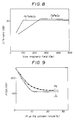
- Fig. 8 is a graph showing the relationship between the bias magnetic field on Oe and the C/N ratio on magnetooptical recording films, one containing Pt and the other containing no Pt.
- Fig. 9 is a graph showing the relationship between the Pt or Pd atom% content and the minimum bias magnetic field H sat. in Oe on magnetooptical recording films containing Pt and Pd, respectively.
- the magnetooptical recording media of the present invention are further illustrated below in more detail.
- the first embodiment of a magnetooptical recording medium 1a of the invention has a structure wherein an enhancement film 3 and a magnetooptical film 4 are laminated in this order on a substrate 2.
- a reflection film 5 is provided on the magnetooptical recording film 4.
- the second embodiment of a magnetooptical recording medium 1b of the invention has a structure wherein a first magnetooptical recording medium A having laminated an enhancement film 3a, a magnetooptical recording film 4a and a reflection film 5a in that order on a substrate 2a and a second magnetooptical recording medium B having laminated an enhancement film 3b, a magnetooptical film 4b and a reflection film 5b in that order on a substrate 2b are laminated to each other through an adhesive layer 6 so that the reflection film 5a of the first magnetooptical recording medium A and the reflection film 5b of the second magnetooptical recording medium B face each other.
- the substrate 2a and substrate 2b may be the same or different, the enhancement film 3a and enhancement film 3b may be the same or different, the magnetooptical recording films 4a and 4b may be the same or different, and the reflection films 5a and 5b may be the same or different.
- substrates 2 and 2a are formed from a cycloolefin random copolymer composition comprising a cycloolefin random copolymer [A] and a cycloolefin random copolymer [B] as defined above.
- n is preferably not more than 3.
- the third embodiment of a magnetooptical recording medium 1b of the present invention has a structure wherein the aforementioned first magnetooptical recording medium A and the aforementioned second magnetooptical recording medium B are laminated to each other through an adhesive layer 6 so that their reflection films 5a and 5b face each other.
- the substrates 2a and 2b may be the same or different so long as they are formed from the aforementioned cycloolefin random copolymer [A], the enhancement films 3a and 3b may be the same or different, the magnetooptical recording films 4a and 4b may be the same or different, and the reflection films 5a and 5b may be the same or different.
- the cycloolefin which is a constituent component of the above-mentioned cycloolefin random compolymers is at least one cycloolefin selected from unsaturated monomers of formula [I].
- the cycloolefins of formula [I] may easily be prepared by a condensation reaction of cyclopentadienes with appropriate olefins or cycloolefins by a Diels-Alder reaction.
- cycloolefins of formula [I] are, for example, the compounds exemplified in Table 1 or, in addition to 1,4,5,8-dimethano-1,2,3,4,4a,5,8,8a-octahydronaphthalene, octahydronaphthalenes as 2-methyl-1,4,5,8-dimethano-1,2,3,4,4a,5,8,8a-octahydronaphthalene, 2-ethyl-1,4,5,8-dimethano-1,2,3,4,4a,5,8,8a-octahydronaphthalene, 2-propyl-1,4,5,8-dimethano-1,2,3,4,4a,5,8,8a-octahydronaphthalene, 2-hexyl-1,4,5,8-dimethano-1,2,3,4,4a,5,8,8a-octahydronaphthalene, 2,3-dimethyl-1,4,5,8-dimethano-1,2,3,4,4a
- the cycloolefin random copolymers [A] and [B] comprise ethylene units and the above-mentioned cycloolefin units as essential components. However, if necessary, said copolymers may contain other copolymerizable unsaturated monomer components so long as they do not hinder the object of the present invention.
- the unsaturated monomers which may be copolymerized, if necessary, with copolymers [A] and [B] include, for example, alpha-olefins having from 3 to 20 carbon atoms such as propylene, 1-butene, 4-methyl-1-pentene, 1-hexene, 1-octene, 1-decene, 1-dodecene, 1-tetradecene, 1-hexadecene, 1-octadecene and 1-eicocene, which may be used in an amount of up to an equimolar amount to the ethylene component unit in the resulting random copolymer.
- recurring units (a) derived from ethylene are generally present in an amount of from 40 to 85 mol%, preferably from 50 to 75 mol%, while recurring units (b) derived from the cycloolefin are generally present in an amount of from 15 to 60 mol%, preferably from 25 to 50 mol%.
- These recurring units (a) and (b) are arranged at random in the substantially linear chain of copolymer [A].
- the molar percentage of recurring units (a) and (b) can be determined by 13C-NMR.
- the fact that the cycloolefin random copolymer [A] is completely soluble in decalin at 135°C confirms that it is substantially linear and free from a gel-forming crosslinked structure.
- the cycloolefin random copolymer [A] has an intrinsic viscosity [ ⁇ ] of from 0.05 to 10 dl/g, preferably from 0.08 to 5 dl/g, as measured in decalin at 135°C.
- the softening temperature (TMA) of the cycloolefin random copolymer [A] as measured by a thermal mechanical analyzer is at least 70°C, preferably from 90 to 250°C, more preferably from 100 to 200°C.
- the softening temperature (TMA) referred to above can be determined by monitoring the thermal deformation behavior of a 1 mm sheet of the copolymer [A] using a thermomechanical analyzer manufactured and sold by Du Pont. More specifically, a quartz needle is vertically placed on the sheet under a load of 49 g and the assembly is heated at a rate of 5°C/min. The temperature at which the needle penetrates into the sheet by a depth of 0.635 mm is the TMA.
- This cycloolefin random copolymer [A] has a glass transition temperature (Tg) of normally from 50° to 230°C, preferably from 70° to 210°C.
- the crystallinity of this cycloolefin random copolymer [A] as measured by X-ray diffractometry is normally from 0 to 10%, preferably from 0 to 7%, more preferably from 0 to 5%.
- the recurring units (a) derived from ethylene are generally present in an amount of from 60 to 98 mol%, preferably from 60 to 95 mol%, and the recurring units (b) derived from the cycloolefin are generally present in an amount of from 2 to 40 mol%, preferably from 5 to 40 mol%.
- the recurring units (a) derived from ethylene and the recurring units (b) derived from the cycloolefin are arranged at random in the substantially linear chain of the copolymer [B].
- the molar percentage of the recurring units (a) and (b) can be determined by 13C-NMR.
- the fact that the cycloolefin random copolymer [B] is completely soluble in decalin at 135°C confirms that it is substantially linear and free from a gel-forming crosslinked structure.
- the cycloolefin random copolymer [B] as mentioned above has an intrinsic viscosity [ ⁇ ] of from 0.05 to 5 dl/g, preferably from 0.08 to 3 dl/g,as measured in decalin at 135°C.
- the softening temperature (TMA) of the cycloolefin random copolymer [B] as measured by a thermal mechanical analyzer is less than 70°C, preferably from -10° to 60°C, and further preferably from 10° to 55°C.
- the cycloolefin random copolymer [B] has a glass transition temperature (Tg) of normally from -30° to 60°C, preferably from -20° to 50°C.
- the crystallinity of this cycloolefin random copolymer [B] as measured by X-ray diffractometry is normally from 0 to 10%, preferably from 0 to 7%, and further preferably from 0 to 5%.
- the cycloolefin random copolymer [A]/the cycloolefin random copolymer [B] weight ratio in the cycloolefin random copolymer composition used for the forming substrate is from 100/0.1 to 100/10, preferably from 100/0.3 to 100/7, more preferably from 100/0.5 to 100/5.
- the substrate used in the present invention which is formed from the above-mentioned cycloolefin random copolymer composition comprising a blend of the above-mentioned components [A] and [B], is such that excellent adhesion between said substrate and the enhancement film used in the invention is maintained even after the substrate stands under conditions of high temperature and humidity.
- the cycloolefin random copolymer [A] or the cycloolefin copolymers [A] and [B] constituting the cycloolefin random copolymer or the cycloolefin random copolymer composition used in the present invention for forming the substrate may all be prepared by the processes described in Japanese Patent L-O-P Publns. Nos. 168708/1985, 120816/1986, 115912/1986 and 115916/1986, Japanese Patent Applns. Nos. 95905/1986 and 95906/1986, Japanese Patent L-O-P Publns. Nos. 271308/1986 and 272216/1986, while suitably selecting the conditions.
- the above-mentioned cycloolefin random copolymer composition may be prepared by known methods, for example, a method wherein the cycloolefin random copolymers [A] and [B] are prepared separately and blended by means of an extruder to prepare the composition, a so-called solution blending method wherein the copolymers [A] and [B] are individually dissolved thoroughly in an appropriate solvent, for example, a saturated hydrocarbon such as butane, hexane, decane or cyclohexane, or an aromatic hydrocarbon such as toluene, benzene or xylene, and the resulting solutions are then blended to prepare the composition, and a method wherein the copolymers [A] and [B] prepared by separate polymerizers are blended in another vessel to prepare the composition.
- a saturated hydrocarbon such as butane, hexane, decane or cyclohexane
- an aromatic hydrocarbon such as toluene, benz
- the cycloolefin copolymer composition thus prepared has an intrinsic viscosity [ ⁇ ] as measured in decalin at 135°C of from 0.05 to 10 dl/g, preferably from 0.08 to 5 dl/g, a softening temperature (TMA) as measured by a thermal mechanical analyzer of from 70 to 250°C, preferably from 80 to 250°C, more preferably from 100 to 200°C, and a glass transition temperature (Tg) of from 70 to 230°C, preferably from 90° to 210°C.
- TMA softening temperature
- Tg glass transition temperature
- the substrate may be made of polymers having recurring units of formula [III] resulting from ring opening of the cycloolefin monomers [I], or polymers having recurring units of formula [IV] resulting from hydrogenation of the units [III]: wherein n and R1 to R12 are as defined above.
- the cycloolefin random copolymer or composition of the present invention may have incorporated therein, if necessary, various additives such as thermal stabilizers, weathering agents, antistatic agents, slip agents, anti-blocking agents, antifoggants, lubricants, dyes, pigments, natural oil, synthetic oil and wax.
- various additives such as thermal stabilizers, weathering agents, antistatic agents, slip agents, anti-blocking agents, antifoggants, lubricants, dyes, pigments, natural oil, synthetic oil and wax.
- the stabilizers which may be optionally incorporated include phenolic antioxidants such as tetrakis[methylene-3-(3,5-di-t-butyl-4-hydroxyphenyl)propionate]methane and ⁇ -(3,5-di-t-butyl-4-hydroxyphenyl) propionic acid alkyl ester (particularly preferred are alkyl esters of less than 18 carbon atoms), phenolic antioxidants such as (2,2′-oxamidobis[ethyl-3-(3,5-di-t-butyl-4-hydroxyphenyl)propionate; metallic salts of fatty acid such as zinc stearate, calcium stearate, calcium 12-hydroxystearate; and fatty esters of polyhydric alcohol such as glycerin monostearate, glycerin distearate, pentaerythritol monostearate, pentaerythritol distearate, pentaerythritol tristearate
- These compounds may be incorporated into the cycloolefin copolymer or composition thereof either singly or in combination.
- phenolic antioxidants in combination with fatty esters of a polyhydric alcohol.
- the fatty esters are preferably those obtained by esterification of part of the alcoholic hydroxyl groups of a polyhydric alcohol of at least three valences.
- the fatty esters of a polyhydric alcohol used above include fatty esters of glycerin such as glycerin monostearate, glycerin monolaurate, glycerin monomyristate, glycerin monopalmitate, glycerin distearate, glycerin dilaurate, and fatty esters of pentaerythritol such as pentaerythritol monostearate, pentaerythritol monolaurate, pentaerythritol distearate, pentaerythritol dilaurate, pentaerythritol tristearate.
- glycerin such as glycerin monostearate, glycerin monolaurate, glycerin monomyristate, glycerin monopalmitate, glycerin distearate, glycerin dilaurate
- the phenolic antioxidants are used in an amount, based on 100 parts by weight of the cycloolefin random copolymer composition, of from 0.01 to 10 parts by weight, preferably from 0.05 to 3 parts by weight, more preferably from 0.1 to 1 part by weight, and the fatty esters of a polyhydric alcohol are used in an amount, based on 100 parts by weight of said composition, of from 0.01 to 10 parts by weight, preferably from 0.05 to 3 parts by weight.
- the above-mentioned cycloolefin random copolymer or composition thereof are used for forming the substrate 2 (2a,2b) .
- This cycloolefin random copolymer or composition has a water absorption which is less than that of the polycarbonate or polymethylmethacrylate hitherto used as the substrate 2 (2a,2b).
- the magnetooptical recording film 4 (4a,4b) formed on said substrate through the enhancement film (protective film) 3 (3a,3b) is less oxidized by the water content in the substrate.
- the substrate 2 (2a, 2b) formed from this cycloolefin copolymer or composition thereof has excellent adhesion to the enhancement film 3 (3a, 3b), and thus oxidation of the magnetooptical recording film 4 (4a, 4b) formed on the substrate through the enhancement film 3 (3a, 3b) is effectively inhibited. Accordingly, the magnetooptical recording media 1a (1b) has excellent in serviceability as well as long-term stability.
- the double-sided magnetooptical recording medium 1b of the second and third recording media of the present invention is further improved in long-term stability, and is also free from warpage and cracks.
- the substrate 2.(2a,2b) formed from the above-mentioned cycloolefin random copolymer or composition thereof has a small refractive index and accordingly a high sensitivity for read-out of the magnetooptical recording film 4 (4a,4b).
- a non-differential driving device may be used at the time of read-out.
- the enhancement film 3 (3a, 3b) used in the present invention is in embodiment 1, or may be, in embodiments 2 or 3, composed of Si3N4, SiN4 (0 ⁇ x ⁇ 4/3), AlN, ZnSe, ZnS, Si or CdS.
- the thickness of the enhancement film is generally from 100 to 1000 ⁇ , preferably 300 to 850 ⁇ .
- Si3N4 and SiN x (0 ⁇ x ⁇ 4/3) from the standpoint of anti-crack properties.
- the enhancement film enhances the sensitivity of said recording media 1a (1b) and also protects the magnetooptical recording film 4 (4a,4b).
- This enhancement film has a refractive index which is larger than that of the substrate.
- the magnetooptical recording film 4 (4a, 4b) preferably used in the present invention includes amorphous metal alloy films having an easy axis of magnetization perpendicular to the film and containing, for example, (i) at least one 3d transition metals element and (iii) at least one rare earth element, preferably those containing (i) at least one 3d transition metals element, (ii) a corrosion resistant metal and (iii) at least one rare earth element.
- Gd Gd, Tb, Dy, Ho, Nd,Sm and Pr.
- At least one rare earth element selected from the above is preferably present in the recording film 4 (4a, 4b) in an amount of from 5 to 50 atom%, more preferably from 8 to 45 atom%, and most preferably from 10 to 40 atom%.
- the magnetooptical recording film 4 (4a, 4b) particularly desirably has the composition mentioned below:
- the magnetooptical recording film 4 (4a, 4b), contains Fe or Co or both.
- the Fe and/or Co is preferably present in the magnetooptical recording film in an amount of at least 40 atom% but not more than 80 atom%, preferably at least 40 atom% but less than 75 atom%, and more preferably at least 40 atom% but not more than 59 atom%.
- the Fe and/or Co are preferably present in the magnetooptical recording film in such an amount that the Co/(Fe + Co) atomic ratio is from 0 to 0.3, preferably from 0 to 0.2, and more preferably from 0.01 to 0.2.
- the magnetooptical recording film has excellent resistance to oxidation and has an easy axis of magnetization perpendicular to the film.
- Fig. 4 shows the relationship between the Co/(Fe + Co) atomic ratio and the noise level in dBm on a magnetooptical recording film of the PtTbFeCo series
- Fig. 5 shows a relationship between the Co/(Fe + Co) atomic ratio and the noise level in dBm on a magnetooptical recording film of the PdTbFeCo series.
- Fig. 6 shows a relationship between the erasion deterioration in terms of ⁇ C/N ratio in dB and the Co/(Fe + Co) atomic ratio on two series of magnetooptical recording films, one of the compositions being PtTbFeCo and the other being PdTbFeCo.
- Preferred magnetooptical recording films 4 (4a, 4b) contain at least one of Pt, Pd, Ti, Zr, Ta, Nb and Mo, preferably Pt or Pd, or both, as a corrosion resistant metal.
- the amount of Pt and/or Pd contained in the preferred magnetooptical recording films is from 5 to 30 atom%, preferably more than 10 atom% but not more than 30 atom%, more preferably more than 10 atom% but less than 20 atom%, and most preferably at least 11 atom% but not more than 19 atom%.
- Fig. 7 shows the relationship between the content of Pt or Pd in the magnetooptical recording film and the decrease of the ⁇ C/N ratio when said recording film is retained for 2000 hours under conditions of 85% RH and 80°C, in the case where the cycloolefin random copolymer composition is used for the substrate.
- a magnetooptical recording film having a composition of Pt13Tb28Fe50Co9 or Pd12Tb28Fe53Co7 is a magnetooptical recording film having a composition of Pt13Tb28Fe50Co9 or Pd12Tb28Fe53Co7, the C/N ratio will not change at all even when it is retained under conditions of 85% RH and 80°C for 1000 hours.
- a magnetooptical recording film having a composition of Tb25Fe68Co7 containing no Pt or Pd has a great decrease in the C/N ratio when it is retained for 1000 hours under conditions of 85% RH and 80°C.
- a sufficiently high C/N ratio can be obtained even by a small bias magnetic field when information is recorded on the magnetooptical recording film or when the information recorded is read out therefrom. If a sufficiently high C/N ratio is obtained by a small bias magnetic field, a magnet for producing the bias magnetic field can be made small in size and, moreover, heat generation from the magnet can be inhibited and hence simplification of a driving device for an optical disc bearing the magnetooptical recording film thereon is made possible. Moreover, because a sufficiently large C/N ratio is obtained by a small bias magnetic field, it becomes easy to design a magnet for magnetic field modulation recording capable of overwriting.
- Fig. 8 shows the relationship between the bias magnetic field and the C/N ratio (dB) of a magnetooptical recording film having a recommended composition of Pt13Tb28Fe50Co9 and of a magnetooptical recording film having a composition of Tb25Fe68Co7.
- Fig. 9 shows the relationship between the content of Pt or Pd and the minimum bias magnetic field (Hsat, (Oe)) on a magnetooptical recording film of the PtTbFeCo series and on a magnetooptical recording film of the PdTbFeCo series.
- the magnetooptical recording film 4 (4a,4b) contains at least one rare earth element (RE).
- RE rare earth element
- Examples of the rare earth element are Nd, Sm, Pr, Ce, Eu, Gd, Tb, Dy and Ho, alone or in combination.
- rare earth elements preferred are Nd, Pr, Gd, Tb and Dy, and particularly preferred is Tb.
- the rare earth elements may be used in combination of two or more, and in this case the combination preferably contains at least 50 atom% of Tb.
- this rare earth element is present in a magnetooptical recording film in an amount such that 0.15 ⁇ x ⁇ 0.45, preferably 0.20 ⁇ x ⁇ 0.4, wherein x represents RE/(RE + Fe + Co) [atomic ratio].
- the present invention it is also possible to improve the Curie temperature, compensation temperature, coercive force Hc or Kerr-rotation angle ⁇ k, or cheapen the cost of production by incorporating various elements into the magnetooptical recording films.
- These elements for the purpose intended may be used, for example, in a proportion of less than 10 atom% based on the total number of atoms of elements constituting the recording film.
- magnetooptical recording films may be composed of (i) at least one 3d transition metal member and (iii) at least one rare earth element as mentioned above.
- Such magnetooptical recording films are preferably those of TbFeCo series, wherein preferably the amount of Tb is from 10 to 40 atom%, that of Fe is from 30 to 90 atom% and that of Co is from 0 to 30 atom%.
- magnetooptical recording films may contain (i) a 3d transition metal and (iii) a rare earth element as mentioned above, and may further contain other elements (e.g. elements of (I) - (VII) mentioned above). These may also be used as the magnetooptical recording film 4.
- the magnetooptical recording films 4 (4a,4b) having a composition described above have an easy axis of magnetization perpendicular to the film plane and that many of them may be an amorphous thin film which exhibits a Kerr hysteresis of a good angular loop, indicating that it is perpendicularly magnetizable and capable of magnetooptical recording.
- Kear hysteresis of a good angular loop used herein we mean that the ratio ⁇ k2/ k1 is at least 0.8 wherein ⁇ k1 is a saturated Kerr-rotation angle that is a Kerr-rotation angle where the external magnetic field is maximum, and k2 is a residual Kerr-rotation angle that is a Kerr-rotation angle where the external magnetic field is zero.
- the thickness of the magnetooptical recording film 4 (4a,4b) is generally from 100 to 50000 ⁇ , preferably from 100 to 3000 ⁇ , and more preferably from about 150 to 2000 ⁇ .
- the reflection film 5 (5a, 5b) is preferably composed of a metal or alloy having a thermal conductivity of not higher than 2 J/cm ⁇ sec ⁇ K, preferably not higher than 1 J/cm ⁇ sec ⁇ K.
- the reflection film 5 (5a, 5b) is also preferably composed of a metal or alloy having a reflectivity of at least 50%, preferably at least 70%, and a thermal conductivity of not higher than 2 J/cm ⁇ sec ⁇ K, preferably not higher than 1 J/cm ⁇ sec. ⁇ K.
- the reflection film 5 is composed of Pt having a thermal conductivity of 0.71 J/cm ⁇ sec ⁇ K, Pd having a thermal conductivity of 0.76 J/cm ⁇ sec ⁇ K, Ti having a thermal conductivity of 0.22 J/cm ⁇ sec ⁇ K, Co having a thermal conductivity of 0.99 J/cm ⁇ sec ⁇ K, Zr having a thermal conductivity of 0.23 J/cm ⁇ sec ⁇ K or alloys thereof.
- the reflection film 5 (5a, 5b) composed of nickel alloy having a refractive index of at least 50%, preferably at least 70%, and a thermal conductivity of not higher than 2 J/cm ⁇ sec ⁇ K, preferably not higher than 1 J/cm ⁇ sec ⁇ K.
- Suitable nickel alloys for constituting the reflection film 5 (5a, 5b) preferably comprise nickel as the primary component and at least one alloying metal selected from silicon, molybdenum, iron, chromium and copper.
- Such nickel alloys contain nickel in an amount of from 30 to 99 atom%, preferably from 50 to 90 atom%.
- nickel alloys usable herein to constitute the reflection film include, for example: Ni-Cr alloys (for example, an alloy of from 30 to 99 atom% of Ni and from 1 to 70 atom% of Cr, preferably an alloy of from 70 to 95 atom% of Ni and from 5 to 30 atom% of Cr), Ni-Si alloys (for example, an alloy of 85 atom% of Ni, 10 atom% of Si, 3 atom% of Cu and 2 atom% of Al).
- Ni-Cu alloys for example, an alloy of 63 atom% of Ni, from 29 to 30 atom% of Cu, from 0.9 to 2 atom% of Fe, from 0.1 to 4 atom% of Si and from 0 to 2.75 atom% of Al).
- Ni-Mo-Fe alloys for example, an alloy of from 60 to 65 atom% of Ni, from 25 to 35 atom% of Mo and 5 atom% of Fe.
- Ni-Mo-Fe-Cr alloys for example, an alloy of from 55 to 60 atom% of Ni, from 15 to 20 tom% of Mo, 6 atom% of Fe, from 12 to 16 atom% of Cr, and 5 atom% of W.
- Ni-Mo-Fe-Cr-Cu alloys for example, an alloy of 60 atom% of Ni, 5 atom% of Mo, 8 atom% of Fe, 21 atom% of Cr, 3 atom% of Cu, 1 atom% of Si, 1 atom% of Mn, and 1 atom% of W; and an alloy of from 44 to 47 atom% of Ni, from 5.5 to 7.5 atom% of Mo, from 21 to 23 atom% of Cr, 0.15 atom% of Cu, 1 atom% of Si, from 1 to 2 atom% of Mn, 2.5 atom% of
- a magnetooptical recording medium having the reflection film 5 (5a, 5b) described herein When compared with a magnetooptical recording medium having a reflection film comprising aluminium, copper or gold, a magnetooptical recording medium having the reflection film 5 (5a, 5b) described herein has an excellent C/N ratio.
- the reflection film proposed herein enhances the resistance to oxidation of the magnetooptical recording film, and thus provides a magnetooptical recording medium capable of maintaining an excellent reliability for a prolonged period of time.
- Preferred reflection films comprise a nickel alloy having a thermal conductivity of not higher than 2 J/cm ⁇ sec ⁇ K, preferably not higher than 1 J/cm ⁇ sec ⁇ K, particularly preferred from the view point of a high C/N ratio, are reflection films composed of a Ni-Cr alloy comprising from 30 to 99 atom% of Ni and from 1 to 70 atom% of Cr, in particular from 70 to 95 atom% of Ni and from 5 to 30 atom% of Cr.
- a reflection film composed of a metal or alloy, in particular a nickel alloy having a reduced thermal conductivity and an increased reflectance is used according to the invention, a large Kerr-rotation angle and a higher reflectance can be realized even with a thinner magnetooptical recording film.
- the thickness of the reflection film 5 (5a, 5b) is normally from 100 to 4000 ⁇ , preferably from about 200 to about 2000 ⁇ .
- the total thickness of the magnetooptical recording film 4 (4a, 4b) and the reflection film 5 (5a, 5b) is normally from 300 to 4600 ⁇ , preferably from about 350 to about 2400 ⁇ .
- the reflection film 5a of the first magnetooptical recording medium A and the reflection film 5b of the second magnetooptical recording medium B are bonded to each other through an adhesive layer 6.
- the adhesive layer 6 used above preferably contains a hot-melt adhesive of polyolefin, EVA, synthetic rubber, polyester or polyamide, and a reactive adhesive of resorcinol, cyanoacrylate, epoxy, urethane or ultraviolet-curing acrylate.
- a hot-melt adhesive of polyolefin, EVA, synthetic rubber, polyester or polyamide
- a reactive adhesive of resorcinol, cyanoacrylate, epoxy, urethane or ultraviolet-curing acrylate.
- polyolefin hot-melt adhesives having a softening point of at least 130°C, preferably exceeding 140°C, and particularly at least 141°C.
- hot-melt adhesives having a high softening point brings about advantages such that no slip-plane occurs between two magnetooptical recording media laminated to each other even when the double-sided magnetooptical recording medium is used for a long period of time under conditions of high temperature and humidity and also deformation such as warpage is small.
- Preferred hot-melt adhesives having a softening point of at least 130°C are polyolefin hot-melt adhesives containing an ethylene/propylene/ ⁇ -olefin random terpolymer (A), a styrene resin (B) and a petroleum resin (C).
- the styrene resin (B) includes polymers and copolymers containing styrene units or styrene derivatives units as constituents such as polystyrene, styrene/ ⁇ -methyl styrene copolymer and styrene/ ⁇ -methyl styrene/vinyl toluene copolymer, and particularly preferred is polystyrene.
- the petroleum resin (C) includes aromatic petroleum resins (e.g. C9 petroleum resin), aliphatic petroleum resins (C5 petroleum resin) and aromatic-aliphatic copolymer petroleum resins (C9 - C5 copolymer resin). Of these petroleum resins, preferred are those having a number average molecular weight of less than 3000, particularly from 500 to 3000, and a softening point of from 80 to 150°C.
- the proportion of the constituent (A) is from 1 to 60% by weight, particularly from 5 to 40% by weight, that of the constituent (B) is from 1 to 30% by weight, particularly from 5 to 20% by weight, and that of the constituent (C) is from 30 to 95% by weight, particularly from 50 to 90% by weight.
- a process for preparing the first magnetooptical recording medium according to the present invention non illustrated.
- the first magnetooptical recording medium may be prepared by depositing an enhancement film and a magnetooptical recording film having their predetermined compositions on a substrate by a known sputtering process or electron beam deposition process, wherein the substrate is maintained at about room temperature (the substrate may be either fixed to or may be rotated), and use is made of a composite target with chips of elements constituting the enhancement film and magnetooptical recording film in the predetermined proportions or an alloy target having the predetermined composition, and a reflection film is then formed on the thus formed magnetooptical recording film by a similar procedure.
- the magnetooptical recording medium as illustrated above may be prepared at room temperature, and the magnetooptical recording film as formed is not always in need of a heat treatment such as annealing to ensure said film has an easy axis of magnetization perpendicular to the film.
- an amorphous alloy film can also be formed on a substrate while heating the substrate to from 50 to 100°C or while cooling the substrate to -50°C.
- biasing a substrate is also possible so that the substrate has a negative potential.
- ions of an inert gas such as argon accelerated in the electric field will hit not only target substances but also the magnetooptical recording film being formed and consequently a magnetooptical recording film having further enhanced characteristics may frequently be obtained.
- a process for preparing the second and third magnetooptical recording media according to the invention is non illustrated.
- the second and third magnetooptical recording media may be prepared by integrating together first and second magnetooptical recording media A and B prepared in the same manner as in the case of the first magnetooptical recording medium la, wherein the reflection films of said media A and B are bonded to each other by means of an adhesive layer 6.
- a hot-melt adhesive is used as the adhesive layer 6, the hot-melt adhesive is applied on the reflection film of the first and/or the second magnetooptical recording medium, for example by a roll coater, and the first and second magnetooptical recording media are then compressed and laminated together, for example by a cold press apparatus.
- adhesion between the substrate and the enhancement film is excellent, and oxidation resistance and long-term stability of magnetooptical recording characteristics are also excellent.
- the second and third magnetooptical recording media of the invention adhesion between the substrate and the enhancement film is excellent and accordingly oxidation resistance is excellent and, moreover no warpage occurs in the substrate.
- the magnetooptical recording media of the invention have excellent magnetooptical recording characteristics and long-term stability of the magnetooptical recording characteristics.
- the present invention is non further illustrated in the following Examples.
- ethylene was fed at a rate of 85 1/hr
- hydrogen was fed at a rate of 6 1/hr
- nitrogen was fed at a rate of 45 1/hr.
- the copolymerization reaction was carried out at 10°C by circulating a refridgerant through a jacket fitted externally to the polymerization reactor.
- the copolymerization was carried out under the conditions as illustrated above, whereupon a polymerization reaction mixture containing an ethylene/DMON random copolymer was obtained.
- the polymerization reaction was stopped by adding a small amount of isopropyl alcohol to the polymerization liquid withdrawn from the bottom of the reactor. Thereafter, the polymerization liquid was poured into a household mixer containing acetone in about three times the volume of the polymerization liquid, while rotating the mixer, thereby depositing the resulting copolymer.
- the deposited copolymer was collected by filtration, dispersed in acetone so that the polymer concentration became about 50 g/l, and the copolymer was treated at the boiling point of acetone for 2 hours. After the above treatment, the copolymer was collected by filtration and dried at 120°C overnight (12 hours) under reduced pressure.
- ethylene/DMON random copolymer (A) had an ethylene unit content of 59 mol% as measured by 13C-NMR analysis, an intrinsic viscosity [ ⁇ ] of 0.42 dl/g as measured at 135°C in decalin, and a softening temperature (TMA) of 154°C.
- the thus-obtained ethylene/DMON copolymer (B) had an ethylene unit of 89 mol% as measured by 13C-NMR analysis, an intrinsic viscosity [ ⁇ ] of 0.44 dl/g as measured at 135°C in decalin and a softening temperature (TMA) of 39°C.
- the (A)/(B) blend thus obtained was incorporated with 0.5% of tetrakis-[methylene-3-(3,5-di-t-butyl-4-hydroxylphenyl) propionate] methane, 0.05% of zinc stearate and 0.5% of glycerin monostearate as stabilizers, each amount being based on the total weight of the copolymers (A) and (B).
- the disc substrate (130 mm ⁇ ) (hereinafter referred to as PO substrate) composed of the cycloolefin random copolymer composition obtained in Preparation Example 1 was subjected to ultrasonic washing with Fleon TE without drying and then used.
- a film of Si3N4 having a thickness of 700 ⁇ as an enhancement layer (protective layer) was formed, and then, using a composite target with chips of Pt and Tb in a predetermined proportion on a Fe-Co target, there was deposited on said enhancement layer by a magnetron sputtering process at from 20 to 50°C a magnetooptical recording film of Pt12Tb30Fe49Co9 having a thickness of 1000 ⁇ as a magnetooptical recording layer under the conditions of an ultimate degree of vacuum of not more than 1.0 ⁇ 10 ⁇ 7 Torr in an Ar atmosphere.
- the magnetooptical recording film obtained was found to be amorphous.
- the composition of the film was determined by ICP emission spectroscopic analysis.
- the thus obtained 130 mm ⁇ disc having the films was left to stand in an air-conditioning apparatus at 85°C and 85% RH for 170 hours. After this test, the appearance of the recording film was inspected microscopically. It was found that there was no change in the appearance of the recording film in comparison with the film before the test and that the adhesion of the film was good.
- the thus obtained 130 mm ⁇ disc having the film was left to stand in an air-conditioning apparatus at 85°C and 85% RH for 170 hours. After this test, the appearance of the recording film was inspected microscopically. It was found that there was no change in the appearance of the recording film in comparison with the film before the test and that the adhesion of the film was good.
- the magnetooptical recording film was found to be amorphous.
- the composition of the recording film was determined by ICP emission spectroscopic analysis.
- the thus obtained 130mm ⁇ disc with the film was allowed to stand in an air-conditioning apparatus at 85°C and 85% RH for 170 hours. After this test, the appearance of the recording film was inspected microscopically. It was found that there was no change in the appearance of the recording film in comparison with the film before the test and that the adhesion of the film was good.
- the thus obtained 130 mm ⁇ disc with the film was allowed to stand in an air-conditioning apparatus at 85°C and 85% RH for 170 hours. After this test, the appearance of the recording film was inspected microscopically. It was found that there was no change in the appearance of the recording film in comparison with the film before the test and that the adhesion of the film was good.
- a disc substrate composed of a polycarbonate resin (PC) was subjected to a drying treatment at 80°C in a sputtering device, evacuated overnight and then subjected to ultrasonic washing with Fleon TE.
- a film of Si3N4 having a thickness of 700 ⁇ as a enhancement layer (protective layer) was formed, and then using a composite target with chips of Pt and Tb in a predetermined proportion on Fe-Co target as a target, there was deposited on said enhancement layer at from 20 to 50°C by a DC magnetron sputtering process a magnetooptical recording film comprising Pt12Tb30Fe49Co9 having a thickness of 1000 ⁇ as a magnetooptical recording layer under the condition of an ultimate degree of vacuum of not more than 1.0 ⁇ 10 ⁇ 7 Torr in an Ar atmosphere.
- the magnetooptical recording film was found to be amorphous.
- the composition of the recording film was determined by ICP emission spectroscopic analysis.
- Comparative Example 1 The procedure of Comparative Example 1 was repeated except that a magnetooptical recording film of Tb25Fe68Co7 having a thickness of 1000 ⁇ was formed as a magnetooptical recording layer in place of the film of Pt12Tb30Fe49Co9 to obtain an optical disc.
- the magnetooptical recording film obtained was found to be amorphous.
- the composition of the recording film was determined by ICP emission spectroscopic analysis.
- Comparative Example 2 The procedure of Comparative Example 2 was repeated except that a film of Tb25Fe68Co7 having a thickness of 1000 ⁇ was formed as a magnetooptical recording layer in place of the film of Pt12Tb30Fe49Co9 to obtain an optical disc.
- a disc substrate (130 mm ⁇ ) of the cycloolefin type random copolymer composition prepared in Preparation Example 1 a disc substrate (130 mm ⁇ ) of PMMA or a disc substrate (130 mm ⁇ ) of PC, there were formed a film having a thickness of 500 ⁇ of a compound given in Table 3 as a protective layer (interlayer) by a sputtering process, a film comprising Tb-Fe having a thickness of 1000 ⁇ as a magnetooptical recording layer on said protective layer by sputtering process and then a film having a thickness of 500 ⁇ as a protective layer on said recording layer by sputtering process.
- the magnetooptical recording media thus obtained were allowed to stand for 7 days at 70°C and 85% RH, and then subjected to a heat cycle test for 7 days wherein the media were allowed to stand alternately at -20°C for 2 hours and at +60°C for 2 hours to measure the coercive force (Hc).
- the magnetooptical recording media of the present invention maintain the initial coercive force stably, while the coercive force of the media having a different protective layer is greatly lowered even when the substrate thereof is the same as that of the media of the present invention. Further, when PMMA or PC is used as the substrate, the coercive force is lowered even when the protective layers are the same as those of the present invention.
- Two magnetooptical discs thus obtained was coated on the reflective layer thereof with a hot-melt adhesive (consisting of 21% by weight of ethylene-propylene-1-butene terpolymer, 10% by weight of polystyrene having a Tg of 110°C and an MFR of 25 g/10 min and 69% by weight of petroleum resin having a number-average molecular weight of 1500) having a softening point of 145°C by means of a roll coater.
- a hot-melt adhesive consisting of 21% by weight of ethylene-propylene-1-butene terpolymer, 10% by weight of polystyrene having a Tg of 110°C and an MFR of 25 g/10 min and 69% by weight of petroleum resin having a number-average molecular weight of 1500
- the record reproducing characteristics of the thus-obtained double-sided magnetooptical recording medium were measured at a recording frequency of 1 MHz (duty ratio 50%) and a linear velocity of 5.4 m/sec.
- the optimum recording laser power was 3.5 mW and the C/N was 50 dB (reproducing laser power was 1.0 mW).
- Example 11 The procedure of Example 11 was repeated except that the magnetooptical recording layer and the reflective layer were changed as shown in Table 7 to obtain double sided magnetooptical recording media. In the same manner as in Example 11, evaluations were made. The results are shown in Table 4.
- Example 11 The procedure of Example 11 was repeated except that the cycloolefin type random copolymer (A) prepared in Polymerization Example (i) of Preparation Example 1 was used in place of the cycloolefin type random copolymer composition obtained in Referential Example 1 to prepare a double-sided magnetooptical recording medium.
- Example 11 In the same manner as in Example 11, the characteristics of the medium was evaluated (but, with regard to ⁇ C/N, the measurement of ⁇ C/N was made after allowing the medium to stand under conditions of 80°C and 85% RH for 1000 hours). The optimum power was 3.5 mW, the C/N was 50 dB, and after the lapse of 1000 hours, ⁇ C/N was 0 dB.).
Landscapes
- Chemical & Material Sciences (AREA)
- Inorganic Chemistry (AREA)
- Optical Record Carriers And Manufacture Thereof (AREA)
- Addition Polymer Or Copolymer, Post-Treatments, Or Chemical Modifications (AREA)
- Holo Graphy (AREA)
- Compositions Of Macromolecular Compounds (AREA)
Claims (12)
- Support d'enregistrement magnéto-optique comportant, dans l'ordre, un substrat, un film de rehaussement, un film d'enregistrement magnéto-optique et un film réfléchissant, et dans lequel :
le substrat est formé d'une composition qui contient :- un copolymère statistique [A] d'éthylène et d'une cyclo-oléfine de formule générale [I] - un copolymère statistique [B] d'éthylène et d'une cyclo-oléfine de formule générale [I], ce copolymère [B] présentant une viscosité intrinsèque [η] de 0,05 à 5 dl/g, mesurée à 135°C dans de la décaline, et une température de ramollissement (TMA) inférieure à 70°C, le rapport pondéral du copolymère [A] au copolymère [B] valant de 100/0,1 à 100/10 ;le film de rehaussement est constitué de Si₃N₄, SiNx (0 < x < ⁴/₃), AlN, ZnSe, ZnS, Si ou CdS ; et
le film réfléchissant est constitué d'un alliage Ni-Cr ou Ni-Cu contenant de 50 à 90 % de Ni, en nombre d'atomes. - Support d'enregistrement conforme à la revendication 1, dans lequel le film d'enregistrement magnéto-optique est un film mince d'un alliage amorphe comprenant (i) au moins un métal de transition 3d, et l'un ou l'autre des constituants suivants ou les deux, à savoir (ii) de 5 à 30 %, en nombre d'atomes, d'au moins un métal résistant à la corrosion, et (iii) au moins un élément des terres rares, et présente un axe de facile aimantation qui est perpendiculaire audit film.
- Support d'enregistrement conforme à la revendication 2, dans lequel ledit métal de transition 3d (i) est Fe et/ou Co.
- Support d'enregistrement conforme à la revendication 2 ou 3, dans lequel ledit métal (ii) résistant à la corrosion, lorsqu'il y en a, est au moins l'un des suivants : Pt, Pd, Ti, Ta, Nb, Zr et Mo.
- Support d'enregistrement conforme à la revendication 4, dans lequel ledit métal (ii) résistant à la corrosion est Pt et/ou Pd.
- Support d'enregistrement conforme à l'une des revendications 2 à 5, dans lequel ledit élément des terres rares (iii), lorsqu'il y en a, est au moins l'un des suivants : Nb, Sm, Pr, Ce, Eu, Gd, Tb, Dy et Ho.
- Support d'enregistrement conforme à l'une des revendications 2 à 6, dans lequel ledit alliage amorphe contient de 40 à 80 %, en nombre d'atomes, du métal de transition 3d (i) et plus de 10 %, mais pas plus de 30 %, en nombre d'atomes, du métal (ii) résistant à la corrosion.
- Support d'enregistrement conforme à l'une des revendications précédentes, dans lequel le film réfléchissant comporte un alliage de nickel.
- Support d'enregistrement magnéto-optique possédant une structure à double face, constitué d'un premier et d'un second supports d'enregistrement magnéto-optique, dans lequel chacun desdits premier et second supports d'enregistrement magnéto-optique comporte, dans l'ordre indiqué, un substrat, un film de rehaussement, un film d'enregistrement et un film réfléchissant, celle sous-structure étant conforme à la revendication 1, et dans lequel le premier support d'enregistrement magnéto-optique est stratifié sur le second support d'enregistrement magnéto-optique, à l'aide d'un film d'adhésif, de telle façon que le film réfléchissant du premier support d'enregistrement magnéto-optique et celui du second support d'enregistrement magnéto-optique se fassent face l'un à l'autre.
- Support d'enregistrement conforme à la revendication 9, dans lequel ledit film d'adhésif est un film d'adhésif thermofusible.
- Support d'enregistrement conforme à la revendication 9 ou 10, dans lequel les premier et second supports d'enregistrement magnéto-optique sont conformes à l'une des revendications 1 à 8.
- Support d'enregistrement conforme à la revendication 9, 10 ou 11, sauf que la composition dont est formé chacun des substrats ne contient pas de copolymère [B].
Applications Claiming Priority (4)
| Application Number | Priority Date | Filing Date | Title |
|---|---|---|---|
| JP264898/88 | 1988-10-20 | ||
| JP26489888 | 1988-10-20 | ||
| JP276738/88 | 1988-11-01 | ||
| JP27673888 | 1988-11-01 |
Publications (3)
| Publication Number | Publication Date |
|---|---|
| EP0366369A2 EP0366369A2 (fr) | 1990-05-02 |
| EP0366369A3 EP0366369A3 (fr) | 1991-02-27 |
| EP0366369B1 true EP0366369B1 (fr) | 1995-12-13 |
Family
ID=26546732
Family Applications (1)
| Application Number | Title | Priority Date | Filing Date |
|---|---|---|---|
| EP89310816A Expired - Lifetime EP0366369B1 (fr) | 1988-10-20 | 1989-10-20 | Milieu d'enregistrement magnéto-optique |
Country Status (8)
| Country | Link |
|---|---|
| EP (1) | EP0366369B1 (fr) |
| KR (1) | KR920007320B1 (fr) |
| CN (2) | CN1016218B (fr) |
| AT (1) | ATE131653T1 (fr) |
| AU (1) | AU606538B2 (fr) |
| CA (1) | CA2001147C (fr) |
| DE (1) | DE68925098T2 (fr) |
| MY (1) | MY104246A (fr) |
Families Citing this family (7)
| Publication number | Priority date | Publication date | Assignee | Title |
|---|---|---|---|---|
| DE69031612T2 (de) * | 1989-07-05 | 1998-03-12 | Mitsui Petrochemical Ind | Magnetooptische Aufzeichnungsmedien |
| CA2014751C (fr) * | 1989-10-19 | 1996-01-23 | Kunihiko Mizumoto | Supports d'enregistrement magneto-optiques |
| JP2903729B2 (ja) * | 1990-12-20 | 1999-06-14 | ソニー株式会社 | 光磁気記録媒体 |
| KR20030070182A (ko) * | 2002-02-21 | 2003-08-29 | 김범 | 게임용 활 시스템 |
| KR101101936B1 (ko) * | 2009-07-23 | 2012-01-02 | (주) 알디텍 | 활의 슈팅 시뮬레이션 시스템 |
| KR102725181B1 (ko) * | 2023-12-05 | 2024-11-04 | 임창남 | 양궁 게임 시스템을 이용한 게임 방법 |
| KR102717040B1 (ko) * | 2023-12-05 | 2024-10-16 | 임창남 | 양궁 게임 시스템 |
Family Cites Families (1)
| Publication number | Priority date | Publication date | Assignee | Title |
|---|---|---|---|---|
| MY103647A (en) * | 1987-12-10 | 1993-08-28 | Mitsui Petrochemical Ind | Magnetooptical recording medium |
-
1989
- 1989-10-19 MY MYPI89001449A patent/MY104246A/en unknown
- 1989-10-20 CA CA002001147A patent/CA2001147C/fr not_active Expired - Fee Related
- 1989-10-20 AT AT89310816T patent/ATE131653T1/de not_active IP Right Cessation
- 1989-10-20 KR KR1019890015121A patent/KR920007320B1/ko not_active Expired
- 1989-10-20 EP EP89310816A patent/EP0366369B1/fr not_active Expired - Lifetime
- 1989-10-20 CN CN89108133A patent/CN1016218B/zh not_active Expired
- 1989-10-20 DE DE68925098T patent/DE68925098T2/de not_active Expired - Fee Related
- 1989-10-20 AU AU43628/89A patent/AU606538B2/en not_active Ceased
-
1991
- 1991-09-28 CN CN91109598A patent/CN1020359C/zh not_active Expired - Fee Related
Also Published As
| Publication number | Publication date |
|---|---|
| DE68925098D1 (de) | 1996-01-25 |
| KR900006926A (ko) | 1990-05-09 |
| AU4362889A (en) | 1990-04-26 |
| KR920007320B1 (ko) | 1992-08-29 |
| EP0366369A3 (fr) | 1991-02-27 |
| MY104246A (en) | 1994-02-28 |
| EP0366369A2 (fr) | 1990-05-02 |
| AU606538B2 (en) | 1991-02-07 |
| DE68925098T2 (de) | 1996-05-15 |
| CA2001147C (fr) | 1995-09-12 |
| CN1064169A (zh) | 1992-09-02 |
| CN1042258A (zh) | 1990-05-16 |
| ATE131653T1 (de) | 1995-12-15 |
| CA2001147A1 (fr) | 1990-04-20 |
| CN1016218B (zh) | 1992-04-08 |
| CN1020359C (zh) | 1993-04-21 |
Similar Documents
| Publication | Publication Date | Title |
|---|---|---|
| WO1995034067A1 (fr) | Support d'enregistrement optique a equilibre de phase eutectique | |
| EP0366369B1 (fr) | Milieu d'enregistrement magnéto-optique | |
| EP0331737B1 (fr) | Support d'enregistrement photomagnetique | |
| EP0320286A2 (fr) | Support d'enregistrement magnéto-optique | |
| EP0423418A2 (fr) | Support d'enregistrement magnétooptique | |
| EP0393576A2 (fr) | Milieux d'enregistrement d'information | |
| JP2682710B2 (ja) | 光磁気記録媒体 | |
| EP0367589B1 (fr) | Milieu d'enregistrement optique | |
| EP0406823B1 (fr) | Milieux d'enregistrement magnéto-optique | |
| JPH05274726A (ja) | 光磁気記録媒体およびその製造方法 | |
| EP0399532A2 (fr) | Supports d'enregistrement optiques | |
| CA1310416C (fr) | Support d'enregistrement magneto-optique | |
| JP2682709B2 (ja) | 光磁気記録媒体 | |
| JP2507592B2 (ja) | 光記録媒体 | |
| KR930008456B1 (ko) | 광자기 기록매체 | |
| JPH03219446A (ja) | 光磁気記録媒体 | |
| JPH04328345A (ja) | 光磁気記録媒体 | |
| EP0454079A2 (fr) | Support d'enregistrement magnéto-optique | |
| KR100194131B1 (ko) | 광학 기록 매체 | |
| JPH04134653A (ja) | 光磁気記録媒体 | |
| Maeno et al. | Properties and structure of AlSiN and AlSiON films | |
| JPH05238148A (ja) | 光磁気記録媒体およびその製造方法 | |
| JPH05242539A (ja) | 光磁気記録媒体およびその製造方法 | |
| JPH04117643A (ja) | 両面記録型光磁気記録媒体 | |
| JPH04170737A (ja) | 光磁気記録媒体 |
Legal Events
| Date | Code | Title | Description |
|---|---|---|---|
| PUAI | Public reference made under article 153(3) epc to a published international application that has entered the european phase |
Free format text: ORIGINAL CODE: 0009012 |
|
| AK | Designated contracting states |
Kind code of ref document: A2 Designated state(s): AT BE CH DE ES FR GB GR IT LI LU NL SE |
|
| PUAL | Search report despatched |
Free format text: ORIGINAL CODE: 0009013 |
|
| AK | Designated contracting states |
Kind code of ref document: A3 Designated state(s): AT BE CH DE ES FR GB GR IT LI LU NL SE |
|
| 17P | Request for examination filed |
Effective date: 19910417 |
|
| 17Q | First examination report despatched |
Effective date: 19931207 |
|
| GRAA | (expected) grant |
Free format text: ORIGINAL CODE: 0009210 |
|
| AK | Designated contracting states |
Kind code of ref document: B1 Designated state(s): AT BE CH DE ES FR GB GR IT LI LU NL SE |
|
| PG25 | Lapsed in a contracting state [announced via postgrant information from national office to epo] |
Ref country code: LI Effective date: 19951213 Ref country code: GR Free format text: LAPSE BECAUSE OF FAILURE TO SUBMIT A TRANSLATION OF THE DESCRIPTION OR TO PAY THE FEE WITHIN THE PRESCRIBED TIME-LIMIT Effective date: 19951213 Ref country code: ES Free format text: THE PATENT HAS BEEN ANNULLED BY A DECISION OF A NATIONAL AUTHORITY Effective date: 19951213 Ref country code: CH Effective date: 19951213 Ref country code: BE Effective date: 19951213 Ref country code: AT Effective date: 19951213 |
|
| REF | Corresponds to: |
Ref document number: 131653 Country of ref document: AT Date of ref document: 19951215 Kind code of ref document: T |
|
| ET | Fr: translation filed | ||
| REF | Corresponds to: |
Ref document number: 68925098 Country of ref document: DE Date of ref document: 19960125 |
|
| ITF | It: translation for a ep patent filed | ||
| PG25 | Lapsed in a contracting state [announced via postgrant information from national office to epo] |
Ref country code: SE Effective date: 19960313 |
|
| REG | Reference to a national code |
Ref country code: CH Ref legal event code: PL |
|
| PLBE | No opposition filed within time limit |
Free format text: ORIGINAL CODE: 0009261 |
|
| STAA | Information on the status of an ep patent application or granted ep patent |
Free format text: STATUS: NO OPPOSITION FILED WITHIN TIME LIMIT |
|
| PG25 | Lapsed in a contracting state [announced via postgrant information from national office to epo] |
Ref country code: LU Free format text: LAPSE BECAUSE OF NON-PAYMENT OF DUE FEES Effective date: 19961031 |
|
| 26N | No opposition filed | ||
| REG | Reference to a national code |
Ref country code: FR Ref legal event code: CD |
|
| NLT1 | Nl: modifications of names registered in virtue of documents presented to the patent office pursuant to art. 16 a, paragraph 1 |
Owner name: MITSUI CHEMICALS, INC. |
|
| REG | Reference to a national code |
Ref country code: GB Ref legal event code: IF02 |
|
| PGFP | Annual fee paid to national office [announced via postgrant information from national office to epo] |
Ref country code: FR Payment date: 20021008 Year of fee payment: 14 |
|
| PGFP | Annual fee paid to national office [announced via postgrant information from national office to epo] |
Ref country code: GB Payment date: 20021016 Year of fee payment: 14 |
|
| PGFP | Annual fee paid to national office [announced via postgrant information from national office to epo] |
Ref country code: DE Payment date: 20021024 Year of fee payment: 14 |
|
| PGFP | Annual fee paid to national office [announced via postgrant information from national office to epo] |
Ref country code: NL Payment date: 20021031 Year of fee payment: 14 |
|
| PG25 | Lapsed in a contracting state [announced via postgrant information from national office to epo] |
Ref country code: GB Free format text: LAPSE BECAUSE OF NON-PAYMENT OF DUE FEES Effective date: 20031020 |
|
| PG25 | Lapsed in a contracting state [announced via postgrant information from national office to epo] |
Ref country code: NL Free format text: LAPSE BECAUSE OF NON-PAYMENT OF DUE FEES Effective date: 20040501 Ref country code: DE Free format text: LAPSE BECAUSE OF NON-PAYMENT OF DUE FEES Effective date: 20040501 |
|
| GBPC | Gb: european patent ceased through non-payment of renewal fee |
Effective date: 20031020 |
|
| PG25 | Lapsed in a contracting state [announced via postgrant information from national office to epo] |
Ref country code: FR Free format text: LAPSE BECAUSE OF NON-PAYMENT OF DUE FEES Effective date: 20040630 |
|
| NLV4 | Nl: lapsed or anulled due to non-payment of the annual fee |
Effective date: 20040501 |
|
| REG | Reference to a national code |
Ref country code: FR Ref legal event code: ST |
|
| PG25 | Lapsed in a contracting state [announced via postgrant information from national office to epo] |
Ref country code: IT Free format text: LAPSE BECAUSE OF NON-PAYMENT OF DUE FEES;WARNING: LAPSES OF ITALIAN PATENTS WITH EFFECTIVE DATE BEFORE 2007 MAY HAVE OCCURRED AT ANY TIME BEFORE 2007. THE CORRECT EFFECTIVE DATE MAY BE DIFFERENT FROM THE ONE RECORDED. Effective date: 20051020 |