EP0366310B1 - Dispositif de distribution pour métal liquide et procédé - Google Patents
Dispositif de distribution pour métal liquide et procédé Download PDFInfo
- Publication number
- EP0366310B1 EP0366310B1 EP89310461A EP89310461A EP0366310B1 EP 0366310 B1 EP0366310 B1 EP 0366310B1 EP 89310461 A EP89310461 A EP 89310461A EP 89310461 A EP89310461 A EP 89310461A EP 0366310 B1 EP0366310 B1 EP 0366310B1
- Authority
- EP
- European Patent Office
- Prior art keywords
- liquid
- vessel
- dispensing
- chamber
- main body
- Prior art date
- Legal status (The legal status is an assumption and is not a legal conclusion. Google has not performed a legal analysis and makes no representation as to the accuracy of the status listed.)
- Expired - Lifetime
Links
- 229910052751 metal Inorganic materials 0.000 title claims description 21
- 239000002184 metal Substances 0.000 title claims description 21
- 238000000034 method Methods 0.000 title claims description 9
- 239000007788 liquid Substances 0.000 claims description 147
- 230000006698 induction Effects 0.000 claims description 21
- 230000001105 regulatory effect Effects 0.000 claims description 16
- 238000010438 heat treatment Methods 0.000 claims description 14
- 230000001276 controlling effect Effects 0.000 claims 1
- 238000005192 partition Methods 0.000 claims 1
- XEEYBQQBJWHFJM-UHFFFAOYSA-N Iron Chemical compound [Fe] XEEYBQQBJWHFJM-UHFFFAOYSA-N 0.000 description 6
- 239000011819 refractory material Substances 0.000 description 6
- 230000006978 adaptation Effects 0.000 description 3
- 238000004140 cleaning Methods 0.000 description 3
- 229910052742 iron Inorganic materials 0.000 description 3
- VYPSYNLAJGMNEJ-UHFFFAOYSA-N Silicium dioxide Chemical compound O=[Si]=O VYPSYNLAJGMNEJ-UHFFFAOYSA-N 0.000 description 2
- 238000001816 cooling Methods 0.000 description 2
- 238000011065 in-situ storage Methods 0.000 description 2
- 239000000843 powder Substances 0.000 description 2
- 239000002893 slag Substances 0.000 description 2
- XLYOFNOQVPJJNP-UHFFFAOYSA-N water Substances O XLYOFNOQVPJJNP-UHFFFAOYSA-N 0.000 description 2
- OKTJSMMVPCPJKN-UHFFFAOYSA-N Carbon Chemical compound [C] OKTJSMMVPCPJKN-UHFFFAOYSA-N 0.000 description 1
- FYYHWMGAXLPEAU-UHFFFAOYSA-N Magnesium Chemical compound [Mg] FYYHWMGAXLPEAU-UHFFFAOYSA-N 0.000 description 1
- HCHKCACWOHOZIP-UHFFFAOYSA-N Zinc Chemical compound [Zn] HCHKCACWOHOZIP-UHFFFAOYSA-N 0.000 description 1
- 239000004411 aluminium Substances 0.000 description 1
- 229910052782 aluminium Inorganic materials 0.000 description 1
- XAGFODPZIPBFFR-UHFFFAOYSA-N aluminium Chemical compound [Al] XAGFODPZIPBFFR-UHFFFAOYSA-N 0.000 description 1
- PNEYBMLMFCGWSK-UHFFFAOYSA-N aluminium oxide Inorganic materials [O-2].[O-2].[O-2].[Al+3].[Al+3] PNEYBMLMFCGWSK-UHFFFAOYSA-N 0.000 description 1
- 239000000919 ceramic Substances 0.000 description 1
- 238000004891 communication Methods 0.000 description 1
- 238000010276 construction Methods 0.000 description 1
- 238000009749 continuous casting Methods 0.000 description 1
- 239000012809 cooling fluid Substances 0.000 description 1
- 239000000110 cooling liquid Substances 0.000 description 1
- 125000004122 cyclic group Chemical group 0.000 description 1
- 238000007872 degassing Methods 0.000 description 1
- 230000001419 dependent effect Effects 0.000 description 1
- 238000001035 drying Methods 0.000 description 1
- 230000000694 effects Effects 0.000 description 1
- 230000003628 erosive effect Effects 0.000 description 1
- 238000004880 explosion Methods 0.000 description 1
- 239000000835 fiber Substances 0.000 description 1
- 229910002804 graphite Inorganic materials 0.000 description 1
- 239000010439 graphite Substances 0.000 description 1
- 230000001939 inductive effect Effects 0.000 description 1
- 238000007689 inspection Methods 0.000 description 1
- 229910001338 liquidmetal Inorganic materials 0.000 description 1
- 229910052749 magnesium Inorganic materials 0.000 description 1
- 239000011777 magnesium Substances 0.000 description 1
- 238000012423 maintenance Methods 0.000 description 1
- 238000005058 metal casting Methods 0.000 description 1
- 150000002739 metals Chemical class 0.000 description 1
- 238000013021 overheating Methods 0.000 description 1
- 230000000717 retained effect Effects 0.000 description 1
- 230000035939 shock Effects 0.000 description 1
- 239000000377 silicon dioxide Substances 0.000 description 1
- 230000003068 static effect Effects 0.000 description 1
- 238000010792 warming Methods 0.000 description 1
- 229910052725 zinc Inorganic materials 0.000 description 1
- 239000011701 zinc Substances 0.000 description 1
Images


Classifications
-
- B—PERFORMING OPERATIONS; TRANSPORTING
- B22—CASTING; POWDER METALLURGY
- B22D—CASTING OF METALS; CASTING OF OTHER SUBSTANCES BY THE SAME PROCESSES OR DEVICES
- B22D11/00—Continuous casting of metals, i.e. casting in indefinite lengths
- B22D11/10—Supplying or treating molten metal
- B22D11/11—Treating the molten metal
-
- B—PERFORMING OPERATIONS; TRANSPORTING
- B22—CASTING; POWDER METALLURGY
- B22D—CASTING OF METALS; CASTING OF OTHER SUBSTANCES BY THE SAME PROCESSES OR DEVICES
- B22D39/00—Equipment for supplying molten metal in rations
Definitions
- This invention relates to dispensing apparatus for molten metal or the like according to the preamble of claim 1 and to a method of dispensing molten metal.
- dispensing apparatus for molten metal or the like comprising a vessel receiving in use a main body of liquid and having dispensing valve means operable to dispense a flow of liquid therefrom, a container defining a chamber, means for supporting the container such that an open mouth thereof is immersed in the main body of liquid to define a head space above the liquid in the chamber, and suction means connected to the container and operable to reduce pressure in the head space so as to draw liquid from the vessel into the chamber, characterised by including an induction heating coil operable to heat liquid in the chamber above the level of the main body of liquid, regulating means operable to regulate the pressure in the head space during periods in which the valve means is closed to raise and lower liquid in the chamber to enable the liquid to be heated prior to dispensing, and sensing means sensing the level of the main body of liquid, the regulating means being operatively connected to the sensing means and operable during periods in which the valve means is open to progressively increase the pressure in the head space to thereby return liquid from the
- An advantage of such apparatus is that a constant head of liquid in the vessel can be maintained during operation of the dispensing valve means by returning a compensating flow of liquid to the vessel from the chamber. The flow of liquid dispensed from the vessel is thereby maintained at a constant rate.
- a further advantage is that where liquid is to be held in the vessel for an extended period prior to operation of the dispensing valve means the liquid can be heated without the necessity for any adaptation to the vessel itself.
- the withdrawn liquid is heated by an induction coil which is located above the vessel and may be external to the container so that in the event of any fracture of the container the withdrawn liquid is automatically returned to the vessel by equalisation of air pressure in the head space with minimal risk of heated liquid contacting the induction coil.
- the induction coil is a water cooled tube because there is a potential explosion hazard if the tube is contacted by molten metal or the like.
- a method of dispensing molten metal or the like from the above disclosed dispensing apparatus including the steps of withdrawing a quantity of liquid into the chamber, opening the dispensing valve means to dispense a flow of liquid from the vessel and regulating the pressure in the head space by operation of the regulating means such that liquid is returned to the main body of liquid at a rate which maintains the level of the main body of liquid substantially constant.
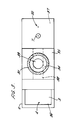
- a dispensing apparatus 1 comprises a vessel 2 receiving a main body 3 of liquid in the form of molten iron delivered to the vessel from a furnace through an inlet 4.
- the vessel 2 has a flat bottom 5 having dispensing valve means comprising a dispensing nozzle 6 which is opened and closed by means of a valve member 7.
- the vessel 2 includes a removable cover 8 and is formed of an insulated refractory material.
- a container 9 comprises a refractory tube 10 which extends vertically upwardly from the vessel 2 and rests on supports 24 mounted on the bottom 5.
- the tube 10 is closed at its upper end by a closure plate 11 which forms an air tight seal therewith.
- a pipe 12 extends through the closure plate 11 and communicates with a suction pump 13 via a first solenoid actuated control valve 14.
- the pipe 12 also communicates with atmosphere at an inlet 27 via a second solenoid actuated control valve 28 which is connected in series with a needle valve 26 allowing the flow rate to be accurately controlled.
- the container 9 defines a chamber 15.
- the tube 10 has an open lower end portion 33 defining an open mouth 16 of the container 9 which is immersed beneath the level 17 of the main body 3 of liquid.
- the chamber 15 is partially occupied by liquid 18 such that the remainder of the chamber is occupied by a head space 19 filled with air which can be evacuated by action of the suction pump 13 and control valve 14.
- a liquid level sensor 20 extends downwardly from the cover 8 into contact with the liquid surface 17 in the vessel 2 in order to provide an electrical signal indicating whether the liquid level reaches a predetermined height 25 above the bottom 5.
- the sensor 20 is connected electrically to a control unit 43 which in turn is connected electrically for the control of the first and second control valves 14, 28 and the pump 13.
- the valves 14, 28 and the control unit 43 provide means for regulating the pressure within chamber 15 during dispensing as described below.
- the control unit 43 is provided with a timer 29 for regulating the operating cycle of the apparatus when heating liquid 18 prior to dispensing as described below.
- An induction coil 21 extends coaxially about the tube 10 at a location above the vessel 2 and is separated from the tube by an annular air gap 22.
- the coil 21 is connected to an electrical power supply (not shown) and is liquid cooled.
- the vessel 2 is filled with liquid 3 via the inlet 4 from a furnace or the like (not shown) to a level which exceeds the predetermined level 25 indicated by sensor 20. Suction is then applied to the head space 19 by operating the pump 13 and opening the control valve 14 such that air is evacuated by means of the pump 13. Liquid 18 is then drawn into the tube 10 until the level 17 of the main body of liquid 3 coincides with the predetermined level 25 as sensed by the sensor 20. The valve 14 is then closed under control of the control unit 43. In this static position as shown in Figure 1 the level 23 of liquid 18 within the container 9 is above the level 17 in the vessel 2 and is such that withdrawn liquid 18 extends through the induction coil 21.
- valve member 7 To dispense liquid from the vessel 3 the valve member 7 is raised to open the nozzle 6 so that a flow of liquid is dispensed.
- the control unit 43 is set to operate in a dispensing mode in which the first control valve 14 remains closed and the second control valve 28 is opened and closed in a controlled manner to admit air to the chamber 15 at a rate limited by needle valve 26.
- the control unit 43 reacts by closing the second control valve 28.
- the control unit reacts by commanding the second control valve 28 to open thereby admitting a flow of air regulated by the needle valve 26 into the chamber 15 such that liquid 18 is partially returned to the main body 3 of liquid.
- the second control valve 28 is again closed. In this way the level 17 is maintained substantially at the predetermined level 25.
- the apparatus thereby provides a constant head of liquid in the vessel 2. Since the flow rate of dispensed liquid is determined by the head of liquid 3 above the nozzle 6 it is thereby possible to obtain a substantially constant dispensed flow rate.
- the advantage of having a constant dispensed flow rate when pouring liquid into a mould is that the quantity of liquid dispensed is proportional to the duration of the flow. A uniform shot weight can therefore be dispensed in successive dispensing operations by timing each dispensing operation to have the same duration.
- the dispensing apparatus 1 is able to provide such heating by means of the induction coil 21.
- the induction coil 21 is actuated to heat the withdrawn liquid 18 by induction currents within the liquid itself whilst providing a flow of cooling liquid within the induction coil to prevent the coil from overheating. Since the coil is located above the vessel 3, the heating effect of the coil is substantially confined to the withdrawn liquid 18.
- valve 28 is then opened to admit air to the head space 19 thereby returning the withdrawn liquid 18 to the vessel 2.
- the returned liquid rapidly disperses amongst the main body 3 of liquid thereby raising the overall liquid temperature.
- control unit 43 is set to operate in standby mode in which liquid 18 is withdrawn, heated and then returned to the main body of liquid repeatedly in a cyclic manner under the control of a timer 29 providing for a two minute period during which liquid 18 is withdrawn followed by a two minute period in which liquid 18 is returned to the main body 3 of liquid.
- the induction coil 21 remains connected to its power supply throughout each cycle, the amount of energy drawn in inductive heating being dependent on the quantity of metal withdrawn so as to lie within the coil at any given time.
- the dispensing apparatus 1 has the inherent fail-safe property that if the refractory tube 10 should fracture whilst liquid 18 is withdrawn then air will be admitted to the tube 10 thereby restoring the pressure of the head space 19 to atmospheric pressure and rapidly returning the withdrawn liquid 18 to the main body of liquid 3. The situation is thereby avoided in which molten metal can escape from the container 9 to come into contact with the induction coil 21. The potentially dangerous situation in which molten metal comes into contact with cooling fluid within the induction coil 21 is thereby avoided.
- the tube 10 may be removed for cleaning, repair or replacement by vertically lifting the tube from the vessel 2 and conveniently the induction coil 21 may remain in situ. Similarly the induction coil 21 may be removed without disturbing the tube 10.
- the cover 8 of the vessel 2 may be removed to facilitate cleaning of the vessel.
- the apparatus 1 is therefore inherently simple to maintain and provides high accessibility for inspection, cleaning and maintenance of its components.
- the apparatus 1 may be used for heating and dispensing zinc, aluminium, iron and other metals including magnesium treated iron for spheroidal graphite.
- the simple construction allows an existing vessel to be modified by the addition of the container and induction coil at minimal expense.
- the dispensing apparatus in accordance with the present invention is ideally suited to situations where the same vessel is to be used for a number of different grades of metal since the vessel 2 is of simple shape and can be rapidly emptied and cleaned therefore when required.
- Apparatus 30 has a modified refractory tube 31 having an integrally formed upper end closure 32 which is bored to receive a pipe 12.
- the pipe 12 is sealed to the end closure 32 and is connected to a suction pump 13 via a first control valve 14 and also to atmosphere at an inlet 27 via a second control valve 28 and a needle valve 26.
- the tube 31 has a lower end portion 33 which is sealed into a recess 34 formed in a support member comprising a shaped block 35 of refractory material.
- the block 35 rests on the bottom 5 of the vessel 2 and supports the tube 31 in an upright position in which it extends upwardly of the vessel 2.
- the vessel 2 is of rectangular cross-section as seen in plan view in Figure 3 and the block 35 is located centrally in the vessel and extends the full width of the vessel so as to divide the vessel into first and second portions 36 and 37 respectively.
- the block 35 is formed with a horizontally extending tunnel 38 communicating between the first and second portions 36 and 37 at a height which is well below the normal level 17 of the main body of liquid 3.
- the block 35 also includes a vertical bore 39 communicating between the recess 34 and the tunnel 38.
- the mouth 16 is located beneath the level 17 of the main body of liquid 3 in its normal position at which it is maintained at a predetermined level 25.
- the lower end 33 of the tube 31 is located at a level which is above the predetermined level 25.
- Molten metal is poured into the first portion of the vessel 2 through an inlet 4 and any slag 41 which may collect on the liquid surface and any turbulence resulting from the pouring in of liquid is confined within the first portion 36 by the presence of the block 35.
- the liquid surface within the second portion 37 is thereby maintained substantially free of any slag and turbulence.
- An automatic control unit 43 is connected to the control valves 14 and 28 and to the suction pump 13 and also receives signals from the liquid level sensor 20.
- the control unit 43 is arranged in its dispensing mode to turn on and off the second control valve 28 during dispensing of liquid through the dispensing nozzle 6 so as to maintain a substantially constant head of liquid in the vessel 2.
- the vessel 2 In use the vessel 2 is charged with liquid through inlet 4 and liquid flows from the first portion 36 into the second portion 37 through the tunnel 28. Liquid is drawn into the chamber 42 by turning on the suction pump 13 with the first control valve 14 in the open position such that the level 23 of liquid within the chamber rises above the level 17 of the main body 3 of liquid in the vessel 2.
- the liquid Prior to dispensing liquid from the vessel the liquid may be heated if required. Liquid 18 partially occupying the chamber 42 may be heated by energising the water cooled induction coil 21 and the heated liquid may then be returned to the main body of liquid 3 by opening the second control valve 28 with the first control valve 14 being turned off. The returned liquid rapidly disperses amongst the main body of liquid 3 thereby raising the overall liquid temperature to compensate for any loss in temperature due to cooling from the vessel 2.
- the apparatus 30 may be operated in standby mode as described above with reference to the apparatus 1 of Figure 1.
- a quantity of liquid equal to or greater than the quantity to be dispensed is withdrawn into the chamber and the pressure in the head space 19 is adjusted until the level 17 of the main body 3 of liquid corresponds to the predetermined level 25.
- the withdrawn liquid 18 is returned to the main body of liquid 3 by the controlled admission of air through the valve 14 to the head space 19 under the control of the control unit 43.
- the returned liquid flows through the vertical bore 39 into the tunnel 38 to replenish liquid withdrawn from the main body of liquid 3.
- valve 14 The flow of air through valve 14 may alternatively be manually controlled.
- the lower end portion 33 of the tube 31 is exposed to less thermal shock than in the case of the embodiment of Figure 1 and is also less susceptible to erosion from contact with molten metal since only the internal surfaces of the tube are contacted by liquid.
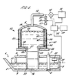
- Figure 4 The further embodiment of Figure 4 is intended to enable a greater mass of liquid to be lifted within the chamber so that a greater mass of liquid can be dispensed in a single operation of the valve means 6,7.
- An alternative dispensing apparatus 50 is shown in Figure 4 where corresponding reference numerals to those of previous Figures are used where appropriate for corresponding elements.
- Apparatus 50 includes a container 51 comprising a furnace portion 52 to which is connected a depending tubular portion 53.
- the container 51 defines a chamber 54 and has a mouth 16 defined by a lower end 33 of the tubular portion 53 which is located in a vessel 2 so as to be normally immersed in a main body 3 of liquid contained in the vessel.
- the furnace portion 52 is supported above the vessel 2 by an annular support 55 defining an aperture 56 through which the tubular portion 53 depends.
- the tubular portion 53 is formed from a tube of refractory material and has an upper end 57 which is sealed to a base plate 58 of the furnace portion 52.
- the furnace portion 52 is of greater diameter than the tubular portion 53, the diameter being determined by the required volume of chamber necessary for lifting the required mass of liquid to be supplied in a single operation to the vessel 2.
- the tubular portion 53 is constructed from a proprietory tube of refractory material
- the furnace portion 52 has in this example a diameter of 0.5m and is made in situ as described below.
- a helical induction coil 21 is supported on the support 55 and refractory material in the form of alumina paste is applied to the coil so as to form a cylindrical lining 59 within the coil.
- the lining 59 is allowed to set by drying in air and a further slip layer 60 of ceramic fibre is inserted within the lining 59.
- an inner cylindrical layer 61 is added in the form of a dry silica powder which is rammed into position and sintered by gradually warming metal in the furnace by applying heat using the coil 21.
- a closure plate 11 is sealed to the upper end of the furnace portion 52 and bored to receive a pipe 12 which connects the chamber 54 to a suction pump 13 via a control valve 14.
- Operation of the apparatus 50 is similar to the operation of apparatus 1 and 30 as described above.
- the alternative apparatus 50 there is no air gap between the furnace portion 52 and the coil 21 since the refractory material makes contact with at least the innermost surfaces of the coil 21.
- the furnace portion 52 can be refurbished by renewing the inner layer 61 using rammed refractory powder which is sintered as described above.
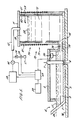
- the apparatus 70 has a container 71 located to one side of the vessel 2 and defining a chamber 72 communicating with the vessel by means of a horizontally extending tube 73 defining a duct 74.
- the container 71 comprises a furnace 75 which is constructed in similar manner to the furnace portion 52 of apparatus 50 and includes a coil 21, a cylindrical lining 59, a slip layer 60 and an inner layer 61.
- the container 71 is closed at its upper end by a closure plate 11 through which a pipe 12 communicates with a suction pump 13 via a control valve 14.
- the chamber 72 has a mouth 16 defined by the duct 74 and located such that the level 17 of the main body 3 of liquid within the vessel 2 is normally maintained at the predetermined level 25 which is above the mouth 16.
- the furnace 75 can be mounted on the same supporting surface 76 as provided for the vessel 2 thus reducing the overall height of the apparatus.
- the dispensing apparatus of any of the above embodiments may additionally be provided with a temperature sensor measuring the temperature of the liquid and the output of the temperature sensor may be used to control the heating of liquid in the standby mode of operation of the apparatus.
- the extent to which the liquid is heated may be controlled by varying the power input to the heating coil or alternatively by regulating the length of time in each cycle during which liquid is withdrawn into the chamber to be heated by the induction heating coil.
Landscapes
- Engineering & Computer Science (AREA)
- Mechanical Engineering (AREA)
- Crucibles And Fluidized-Bed Furnaces (AREA)
- Casting Support Devices, Ladles, And Melt Control Thereby (AREA)
- Vertical, Hearth, Or Arc Furnaces (AREA)
Claims (14)
- Appareil de distribution (1) de métal fondu ou autre, comprenant une cuve (2) recevant, lors de l'utilisation, une masse principale (3) de liquide et comportant des moyens (6, 7) formant soupape de distribution, pouvant être actionnés pour distribuer un courant de liquide, un réservoir (9) délimitant une chambre (15), des moyens (24) destinés à supporter le réservoir de manière que l'embouchure ouverte (16) de celui-ci soit immergée dans la masse principale de liquide pour former un espace de charge ou de pression (19) au-dessus du liquide se trouvant dans la chambre, et un dispositif d'aspiration (13) relié au réservoir et pouvant fonctionner pour réduire la pression régnant dans l'espace de charge susdit afin d'aspirer du liquide depuis la cuve vers la chambre, cet appareil étant caractérisé en ce qu'il comprend une bobine de chauffage par induction (21) pouvant fonctionner pour chauffer le liquide se trouvant dans la chambre au-dessus du niveau (17) de la masse principale de liquide, des moyens de réglage (43, 14, 28) pouvant fonctionner pour régler la pression régnant dans l'espace de charge durant des périodes au cours desquelles les moyens formant soupape sont fermés pour élever et abaisser le liquide dans la chambre en vue de permettre le chauffage de ce liquide avant sa distribution, et des moyens détecteurs (20) destinés à déceler le niveau (17) de la masse principale de liquide, les moyens de réglage étant connectés, pour le fonctionnement, aux moyens détecteurs et pouvant fonctionner durant des périodes au cours desquelles les moyens formant soupape sont ouverts pour augmenter progressivement la pression régnant dans l'espace de charge en vue de renvoyer ainsi le liquide depuis la chambre vers la cuve, de manière que le niveau de la masse principale de liquide soit maintenu sensiblement constant durant la distribution du liquide.
- Appareil de distribution suivant la revendication 1, dans lequel le réservoir est constitué par un tube réfractaire (10) supporté sensiblement verticalement de manière à s'étendre vers le haut par rapport à la cuve.
- Appareil de distribution suivant la revendication 2, dans lequel le tube réfractaire comporte une partie extrême inférieure (33) formant l'embouchure du réservoir.
- Appareil de distribution suivant la revendication 2, dans lequel les moyens de support consistent en un élément de support (35) relié à la partie extrême inférieure (33) du tube et délimitant l'embouchure du réservoir.
- Appareil de distribution suivant la revendication 4, dans lequel l'élément de support subdivise la cuve en une première partie (36) comportant une entrée (4), et une seconde partie (37) depuis laquelle le liquide peut être distribué par les moyens formant soupape de distribution, cet appareil comprenant en outre un tunnel (38) délimitant un parcours d'écoulement entre la première partie et la seconde partie, en dessous du niveau normal (17) de la masse principale de liquide.
- Appareil de distribution suivant l'une quelconque des revendications 2 à 5, dans lequel le tube comporte une partie extrême supérieure (57) reliée à une partie formant four (52) du réservoir, la partie formant four étant d'une section transversale plus élevée que celle du tube.
- Appareil de distribution suivant la revendication 1, dans lequel le réservoir comporte une partie formant four (75) localisée d'un côté de la cuve et reliée à celle-ci par des moyens de connexion (73) définissant l'embouchure (74) du réservoir.
- Appareil de distribution suivant l'une quelconque des revendications 2 à 5, dans lequel la bobine de chauffage par induction est localisée au-dessus de la cuve, et le tube s'étend à travers cette bobine, celle-ci étant séparée de ce tube par un intervalle d'air annulaire (22).
- Appareil de distribution suivant l'une quelconque des revendications précédentes, dans lequel les moyens de régulation comprennent un premier moyen formant soupape (14) connecté entre le dispositif d'aspiration et la chambre, et un second moyen formant soupape (28) relié entre la chambre et l'atmosphère (27).
- Appareil de distribution suivant la revendication 9, dans laquelle le second moyen formant soupape consiste en une soupape de commande (26, 28) pour gaz, pouvant être mise en fonctionnement pour admettre du gaz dans l'espace de charge, à une vitesse contrôlée.
- Appareil de distribution suivant l'une quelconque des revendications précédentes, comprenant un compteur de temps (29) pouvant être mis en fonctionnement pour contrôler les moyens de régulation durant des périodes au cours desquelles les moyens formant soupape sont fermés, afin d'élever et d'abaisser cycliquement le niveau de liquide dans la chambre, pour permettre ainsi le chauffage de ce liquide avant sa distribution.
- Procédé de distribution d'un métal fondu ou similaire depuis un appareil de distribution suivant la revendication 1, ce procédé comprenant les phases suivantes : l'enlèvement d'une certaine quantité de liquide vers la chambre susdite, l'ouverture des moyens formant soupape de distribution pour distribuer un débit de liquide depuis la cuve, et le réglage de la pression régnant dans l'espace de charge par mise en fonctionnement des moyens de régulation, de manière que du liquide soit retourné à la masse principale de liquide à un débit qui entretient le niveau de la masse principale de liquide, dans un état essentiellement constant.
- Procédé suivant la revendication 12, comprenant la phase de chauffage du liquide durant des périodes au cours desquelles les moyens formant soupape sont fermés en prélevant vers la chambre une certaine quantité de liquide depuis la masse principale de liquide, la phase de chauffage du liquide prélevé et le retour d'au moins une partie de ce liquide prélevé vers la masse principale de liquide.
- Procédé suivant la revendication 13, dans laquelle du liquide est prélevé cycliquement, chauffé et renvoyé à la masse principale de liquide durant des périodes au cours desquelles les moyens formant soupape sont fermés à l'intervention d'un compteur de temps (29) contrôlant les moyens de réglage.
Priority Applications (1)
| Application Number | Priority Date | Filing Date | Title |
|---|---|---|---|
| AT89310461T ATE83956T1 (de) | 1988-10-13 | 1989-10-12 | Vorrichtung zum verteilen von fluessigem metall und verfahren dazu. |
Applications Claiming Priority (4)
| Application Number | Priority Date | Filing Date | Title |
|---|---|---|---|
| GB8824000 | 1988-10-13 | ||
| GB888824000A GB8824000D0 (en) | 1988-10-13 | 1988-10-13 | Dispensing apparatus for molten metal |
| GB898916295A GB8916295D0 (en) | 1989-07-17 | 1989-07-17 | Dispensing apparatus for molten metal |
| GB8916295 | 1989-07-17 |
Publications (2)
| Publication Number | Publication Date |
|---|---|
| EP0366310A1 EP0366310A1 (fr) | 1990-05-02 |
| EP0366310B1 true EP0366310B1 (fr) | 1992-12-30 |
Family
ID=26294512
Family Applications (1)
| Application Number | Title | Priority Date | Filing Date |
|---|---|---|---|
| EP89310461A Expired - Lifetime EP0366310B1 (fr) | 1988-10-13 | 1989-10-12 | Dispositif de distribution pour métal liquide et procédé |
Country Status (9)
| Country | Link |
|---|---|
| US (1) | US5056692A (fr) |
| EP (1) | EP0366310B1 (fr) |
| JP (1) | JPH0366469A (fr) |
| KR (1) | KR900006046A (fr) |
| AU (1) | AU615111B2 (fr) |
| DE (1) | DE68904163T2 (fr) |
| DK (1) | DK510589A (fr) |
| ES (1) | ES2038414T3 (fr) |
| GB (1) | GB2223969A (fr) |
Families Citing this family (16)
| Publication number | Priority date | Publication date | Assignee | Title |
|---|---|---|---|---|
| CS91991A2 (en) * | 1990-04-04 | 1991-11-12 | Monks James Herbert | Method of molten metal's flow regulation and device for this method realization |
| DE4011392B4 (de) * | 1990-04-09 | 2004-04-15 | Ald Vacuum Technologies Ag | Verfahren und Vorrichtung zur Formung eines Gießstrahls |
| US5272718A (en) * | 1990-04-09 | 1993-12-21 | Leybold Aktiengesellschaft | Method and apparatus for forming a stream of molten material |
| AT396439B (de) * | 1991-05-13 | 1993-09-27 | Sommerhuber Franz | Vorrichtung für den kokillenguss grossdimensionaler profile, insbesondere hohlprofile, aus leichtmetall |
| US5282608A (en) * | 1992-12-03 | 1994-02-01 | Cmi International | Induction heated metal pouring apparatus |
| GB2285588B (en) * | 1994-01-17 | 1997-04-30 | Ea Tech Ltd | Method and apparatus for mixing a metal matrix composite |
| DE19800853A1 (de) * | 1998-01-13 | 1999-07-15 | Ald Vacuum Techn Gmbh | Geschlossener, evakuierbarer Tiegel zum induktiven Schmelzen oder Überhitzen von Metallen, Legierungen oder anderen elektrisch leitfähigen Werkstoffen |
| US6500228B1 (en) | 2001-06-11 | 2002-12-31 | Alcoa Inc. | Molten metal dosing furnace with metal treatment and level control and method |
| US6503292B2 (en) | 2001-06-11 | 2003-01-07 | Alcoa Inc. | Molten metal treatment furnace with level control and method |
| WO2004090491A2 (fr) * | 2003-03-31 | 2004-10-21 | Saudi Arabian Oil Company | Mesure du niveau de soufre fondu dans des reservoirs |
| WO2005023459A1 (fr) * | 2003-09-11 | 2005-03-17 | Equipment Merchants International, Inc. | Systeme d'alimentation fluidique pour moulage |
| US20070290382A1 (en) * | 2006-06-14 | 2007-12-20 | Marc Laverdiere | Systems and methods for managing heat transfer in a fluid handling device |
| NO333512B1 (no) * | 2007-12-03 | 2013-06-24 | Norsk Hydro As | Anordning ved utstyr for kontinuerlig eller semi-kontinuerlig stoping av metall |
| CN201565578U (zh) * | 2009-12-12 | 2010-09-01 | 南方铝业(中国)有限公司 | 铝合金熔炼用真空排气装置 |
| NO341337B1 (en) * | 2015-07-03 | 2017-10-16 | Norsk Hydro As | Equipment for continuous or semi-continuous casting of metal with improved metal filling arrangement |
| NO20181185A1 (en) * | 2018-09-11 | 2020-03-12 | Norsk Hydro As | Casting Equipment |
Family Cites Families (10)
| Publication number | Priority date | Publication date | Assignee | Title |
|---|---|---|---|---|
| US307845A (en) * | 1884-11-11 | Joseph s | ||
| AU422827B2 (en) * | 1967-10-03 | 1972-03-28 | Monzino Riotinto Of Australia Limited | Continuous degassing of metals |
| DE1960283A1 (de) * | 1968-12-18 | 1970-07-09 | Pennwalt Corp | Vakuumentgasungsvorrichtung fuer die Verwendung beim Stranggiessen von Metallen und Verfahren zum Stranggiessen von schmelzfluessigem Metall,waehrend es einer Vakuumentgasung unterworfen ist |
| US3653426A (en) * | 1969-06-12 | 1972-04-04 | American Standard Inc | Furnace pouring and casting system |
| DE2834577A1 (de) * | 1978-08-07 | 1980-02-21 | Bbc Brown Boveri & Cie | Vorrichtung zum dosierten vergiessen von schmelzfluessigem metall |
| US4449568A (en) * | 1980-02-28 | 1984-05-22 | Allied Corporation | Continuous casting controller |
| JPS56168940A (en) * | 1980-05-28 | 1981-12-25 | Nisshin Steel Co Ltd | Continuous casting method from undeoxidized molten steel |
| JPH0620618B2 (ja) * | 1985-03-26 | 1994-03-23 | 日立電線株式会社 | 連続鋳造方法及びその装置 |
| JPS63119966A (ja) * | 1986-11-10 | 1988-05-24 | Toshiba Mach Co Ltd | 加圧式溶湯保温炉における溶湯供給系内溶湯の急速排湯方法 |
| JPS63174765A (ja) * | 1987-01-14 | 1988-07-19 | Hitachi Cable Ltd | 溶融金属用連続真空脱ガス装置 |
-
1989
- 1989-10-06 US US07/418,207 patent/US5056692A/en not_active Expired - Fee Related
- 1989-10-11 AU AU42784/89A patent/AU615111B2/en not_active Ceased
- 1989-10-12 GB GB8923039A patent/GB2223969A/en not_active Withdrawn
- 1989-10-12 EP EP89310461A patent/EP0366310B1/fr not_active Expired - Lifetime
- 1989-10-12 DE DE8989310461T patent/DE68904163T2/de not_active Expired - Fee Related
- 1989-10-12 KR KR1019890014639A patent/KR900006046A/ko not_active Application Discontinuation
- 1989-10-12 ES ES198989310461T patent/ES2038414T3/es not_active Expired - Lifetime
- 1989-10-13 DK DK510589A patent/DK510589A/da not_active Application Discontinuation
- 1989-10-13 JP JP1265361A patent/JPH0366469A/ja active Pending
Also Published As
| Publication number | Publication date |
|---|---|
| AU615111B2 (en) | 1991-09-19 |
| KR900006046A (ko) | 1990-05-07 |
| DK510589D0 (da) | 1989-10-13 |
| US5056692A (en) | 1991-10-15 |
| DE68904163T2 (de) | 1993-04-29 |
| EP0366310A1 (fr) | 1990-05-02 |
| ES2038414T3 (es) | 1993-07-16 |
| JPH0366469A (ja) | 1991-03-22 |
| AU4278489A (en) | 1990-04-26 |
| DE68904163D1 (de) | 1993-02-11 |
| GB8923039D0 (en) | 1989-11-29 |
| GB2223969A (en) | 1990-04-25 |
| DK510589A (da) | 1990-04-14 |
Similar Documents
| Publication | Publication Date | Title |
|---|---|---|
| EP0366310B1 (fr) | Dispositif de distribution pour métal liquide et procédé | |
| US5215141A (en) | Apparatus and method for controlling the countergravity casting of molten metal into molds | |
| RU2005136813A (ru) | Способ регулирования потока, а также донное выпускное устройство для металлургической емкости | |
| GB2068096A (en) | Furnace for pouring metered quantities of metal melt | |
| US3663730A (en) | Molten metal dispensing equipment | |
| US6819704B2 (en) | Induction melting furnace with metered discharge | |
| JPH037468B2 (fr) | ||
| US3921859A (en) | Siphon for molten metals with suction actuator | |
| JPH0539818Y2 (fr) | ||
| JPH03258448A (ja) | ダイカストマシン用電磁給湯装置 | |
| JPS6232020B2 (fr) | ||
| WO2005023459A1 (fr) | Systeme d'alimentation fluidique pour moulage | |
| JPH08164459A (ja) | 加圧式注湯炉の自動注湯制御方法 | |
| US4632174A (en) | Double boiler furnace for vertical ascending pipe casting | |
| RU1449U1 (ru) | Устройство для заливки жидкого металла в литейные формы | |
| JP2005000964A (ja) | 低圧鋳造システム | |
| WO2023154526A1 (fr) | Four de coulée | |
| JP4274616B2 (ja) | 溶融金属供給装置 | |
| CA1052569A (fr) | Pompe a garniture refractaire | |
| JPH02127955A (ja) | 溶融金属の給湯方法と給湯装置 | |
| JPS646869B2 (fr) | ||
| JPS6359790B2 (fr) | ||
| JPS646867B2 (fr) | ||
| JPH0149584B2 (fr) | ||
| GB2289936A (en) | Electric melting furnace with pressure actuated discharge |
Legal Events
| Date | Code | Title | Description |
|---|---|---|---|
| PUAI | Public reference made under article 153(3) epc to a published international application that has entered the european phase |
Free format text: ORIGINAL CODE: 0009012 |
|
| AK | Designated contracting states |
Kind code of ref document: A1 Designated state(s): AT BE CH DE ES FR GB GR IT LI LU NL SE |
|
| 17P | Request for examination filed |
Effective date: 19900907 |
|
| 17Q | First examination report despatched |
Effective date: 19910711 |
|
| RTI1 | Title (correction) | ||
| RAP1 | Party data changed (applicant data changed or rights of an application transferred) |
Owner name: CHAMBERLIN & HILL PLC Owner name: ELECTRICITY ASSOCIATION SERVICES LIMITED |
|
| GRAA | (expected) grant |
Free format text: ORIGINAL CODE: 0009210 |
|
| AK | Designated contracting states |
Kind code of ref document: B1 Designated state(s): AT BE CH DE ES FR GB GR IT LI LU NL SE |
|
| PG25 | Lapsed in a contracting state [announced via postgrant information from national office to epo] |
Ref country code: SE Effective date: 19921230 Ref country code: LI Effective date: 19921230 Ref country code: GR Free format text: LAPSE BECAUSE OF FAILURE TO SUBMIT A TRANSLATION OF THE DESCRIPTION OR TO PAY THE FEE WITHIN THE PRESCRIBED TIME-LIMIT Effective date: 19921230 Ref country code: CH Effective date: 19921230 Ref country code: AT Effective date: 19921230 |
|
| REF | Corresponds to: |
Ref document number: 83956 Country of ref document: AT Date of ref document: 19930115 Kind code of ref document: T |
|
| REF | Corresponds to: |
Ref document number: 68904163 Country of ref document: DE Date of ref document: 19930211 |
|
| ET | Fr: translation filed | ||
| ITF | It: translation for a ep patent filed | ||
| REG | Reference to a national code |
Ref country code: CH Ref legal event code: PL |
|
| REG | Reference to a national code |
Ref country code: ES Ref legal event code: FG2A Ref document number: 2038414 Country of ref document: ES Kind code of ref document: T3 |
|
| PGFP | Annual fee paid to national office [announced via postgrant information from national office to epo] |
Ref country code: ES Payment date: 19930927 Year of fee payment: 5 |
|
| REG | Reference to a national code |
Ref country code: GB Ref legal event code: 732E |
|
| PG25 | Lapsed in a contracting state [announced via postgrant information from national office to epo] |
Ref country code: LU Free format text: LAPSE BECAUSE OF NON-PAYMENT OF DUE FEES Effective date: 19931031 |
|
| PGFP | Annual fee paid to national office [announced via postgrant information from national office to epo] |
Ref country code: NL Payment date: 19931031 Year of fee payment: 5 |
|
| PLBE | No opposition filed within time limit |
Free format text: ORIGINAL CODE: 0009261 |
|
| STAA | Information on the status of an ep patent application or granted ep patent |
Free format text: STATUS: NO OPPOSITION FILED WITHIN TIME LIMIT |
|
| PGFP | Annual fee paid to national office [announced via postgrant information from national office to epo] |
Ref country code: BE Payment date: 19931215 Year of fee payment: 5 |
|
| 26N | No opposition filed | ||
| REG | Reference to a national code |
Ref country code: FR Ref legal event code: TP |
|
| PG25 | Lapsed in a contracting state [announced via postgrant information from national office to epo] |
Ref country code: ES Free format text: LAPSE BECAUSE OF EXPIRATION OF PROTECTION Effective date: 19941013 |
|
| PG25 | Lapsed in a contracting state [announced via postgrant information from national office to epo] |
Ref country code: BE Effective date: 19941031 |
|
| NLS | Nl: assignments of ep-patents |
Owner name: EA TECHNOLOGY LIMITED TE CAPENHURST EN CHAMBERLIN |
|
| BERE | Be: lapsed |
Owner name: CHAMBERLIN & HILL P.L.C. P.L.C. Effective date: 19941031 Owner name: EA TECHNOLOGY LTD Effective date: 19941031 |
|
| PG25 | Lapsed in a contracting state [announced via postgrant information from national office to epo] |
Ref country code: NL Effective date: 19950501 |
|
| NLV4 | Nl: lapsed or anulled due to non-payment of the annual fee | ||
| ITPR | It: changes in ownership of a european patent |
Owner name: CESSIONE;EA TECHNOLOGY LIMITED |
|
| PGFP | Annual fee paid to national office [announced via postgrant information from national office to epo] |
Ref country code: FR Payment date: 19980923 Year of fee payment: 10 |
|
| PGFP | Annual fee paid to national office [announced via postgrant information from national office to epo] |
Ref country code: GB Payment date: 19981022 Year of fee payment: 10 |
|
| PGFP | Annual fee paid to national office [announced via postgrant information from national office to epo] |
Ref country code: DE Payment date: 19981221 Year of fee payment: 10 |
|
| REG | Reference to a national code |
Ref country code: ES Ref legal event code: FD2A Effective date: 19990601 |
|
| PG25 | Lapsed in a contracting state [announced via postgrant information from national office to epo] |
Ref country code: GB Free format text: LAPSE BECAUSE OF NON-PAYMENT OF DUE FEES Effective date: 19991012 |
|
| GBPC | Gb: european patent ceased through non-payment of renewal fee |
Effective date: 19991012 |
|
| PG25 | Lapsed in a contracting state [announced via postgrant information from national office to epo] |
Ref country code: FR Free format text: LAPSE BECAUSE OF NON-PAYMENT OF DUE FEES Effective date: 20000630 |
|
| PG25 | Lapsed in a contracting state [announced via postgrant information from national office to epo] |
Ref country code: DE Free format text: LAPSE BECAUSE OF NON-PAYMENT OF DUE FEES Effective date: 20000801 |
|
| REG | Reference to a national code |
Ref country code: FR Ref legal event code: ST |
|
| PG25 | Lapsed in a contracting state [announced via postgrant information from national office to epo] |
Ref country code: IT Free format text: LAPSE BECAUSE OF NON-PAYMENT OF DUE FEES Effective date: 20051012 |