EP0366105A2 - Dispositif de fixation pour outil, en particulier pour meules de rectification - Google Patents
Dispositif de fixation pour outil, en particulier pour meules de rectification Download PDFInfo
- Publication number
- EP0366105A2 EP0366105A2 EP89119799A EP89119799A EP0366105A2 EP 0366105 A2 EP0366105 A2 EP 0366105A2 EP 89119799 A EP89119799 A EP 89119799A EP 89119799 A EP89119799 A EP 89119799A EP 0366105 A2 EP0366105 A2 EP 0366105A2
- Authority
- EP
- European Patent Office
- Prior art keywords
- clamping
- clamping device
- tool
- spindle
- axial
- Prior art date
- Legal status (The legal status is an assumption and is not a legal conclusion. Google has not performed a legal analysis and makes no representation as to the accuracy of the status listed.)
- Granted
Links
Images

Classifications
-
- B—PERFORMING OPERATIONS; TRANSPORTING
- B27—WORKING OR PRESERVING WOOD OR SIMILAR MATERIAL; NAILING OR STAPLING MACHINES IN GENERAL
- B27B—SAWS FOR WOOD OR SIMILAR MATERIAL; COMPONENTS OR ACCESSORIES THEREFOR
- B27B5/00—Sawing machines working with circular or cylindrical saw blades; Components or equipment therefor
- B27B5/29—Details; Component parts; Accessories
- B27B5/30—Details; Component parts; Accessories for mounting or securing saw blades or saw spindles
- B27B5/32—Devices for securing circular saw blades to the saw spindle
- B27B5/325—Devices for securing circular saw blades to the saw spindle using fluid pressure means
-
- B—PERFORMING OPERATIONS; TRANSPORTING
- B24—GRINDING; POLISHING
- B24B—MACHINES, DEVICES, OR PROCESSES FOR GRINDING OR POLISHING; DRESSING OR CONDITIONING OF ABRADING SURFACES; FEEDING OF GRINDING, POLISHING, OR LAPPING AGENTS
- B24B45/00—Means for securing grinding wheels on rotary arbors
Definitions
- the invention relates to a clamping device for tools, in particular for grinding wheels, according to the preamble of claim 1.
- the tool is provided with the clamping part.
- the hydraulic medium After being pushed onto the spindle, the hydraulic medium must be pressurized so that the clamping part is elastically expanded.
- the tool is clamped radially on the spindle and is also centered radially. To ensure an exact position of the tool, it is pushed onto the clamping bush up to a stop on the clamping device.
- the invention has for its object to design the generic clamping device so that it allows easy replacement of the tools, which can still be reliably clamped.
- the elastically expandable clamping part is no longer part of the tool, but is provided on the spindle.
- the tools can therefore be simple. In particular, conventional tools can now also be hydraulically clamped. If a tool is to be removed from the clamping device according to the invention, then only the clamping screw has to be screwed back into its pressure relief position. Then the tool can be easily pushed off the clamping bush. If a tool is to be clamped, it is only necessary to screw the clamping screw back into its clamping position from the pressure relief position. The pressure medium in the bore of the spindle is brought to the desired clamping pressure. This makes changing and clamping the tools very time-saving and, above all, easy.
- the tool With the axial tendon, in addition to its radial centering and clamping, the tool is also axially fixed and clamped.
- the axial tendon is positively connected to the tool in the axial direction, so that the tool can then be moved in the axial direction during the axial adjustment of the axial tendon and can be pulled, for example, against a stop surface.
- This allows the tool to be positioned correctly in the clamping device both in the radial and in the axial direction.
- the tool is therefore precisely aligned on the spindle or its clamping bush.
- the clamping device is used to clamp tools, in particular grinding wheels.
- the clamping device is provided on a machine and has a housing 1, in which a spindle 2 with roller bearings 3, 4 is rotatably mounted.
- the spindle 2 protrudes forward from the housing 1 and carries at the free end a clamping bush 5 which is designed as a hydraulic bushing and has one or more chambers 6 which are axially closed.
- the chamber 6 is delimited radially inwards by the spindle 2 and radially outwards by an elastically deformable wall section 7 of the clamping bush 5.
- At least one transverse bore 8 which penetrates the spindle 2 opens into the chamber 6 and connects the chamber 6 to a bore 9 which penetrates the spindle 2 centrally and axially.
- the clamping bush 5 is mounted on the free end of the spindle 2.
- the bore 9 is closed by a filling valve 10, via which a pressure medium is introduced into the bore 9.
- the bore 9 is closed by a clamping screw 11 which is screwed into a threaded bore 12 of the spindle 2 which is open at the end.
- a tensioning piston 13 which under the pressure of the pressure medium in the bore 9 rests with its end face on the clamping screw 11 (Fig. 1).
- the tensioning piston 13 is guided in a sealed manner in the bore 9, so that the pressure medium cannot reach the outside between the tensioning piston and the wall of the bore 9.
- the spindle 2 is provided in the area outside the housing 1 with a collar 14 which has an enlarged outer diameter and which carries an external thread 15.
- a fling ring 16 is screwed onto the collar 14 and has, on its side facing the clamping bush 5, a front-side recess 17 which is coaxial with the spindle 2 and which is provided with an internal thread 18.
- a ring 19 can be screwed into this recess 17.
- the centrifugal ring On the side opposite the recess 17, the centrifugal ring is provided with two coaxial annular depressions 20 and 21, in which the housing 1 engages with play with corresponding annular webs 22 and 23. They are also coaxial to the spindle 2.
- two stops 24 and 25 are provided diametrically opposite one another, which are preferably designed as studs. The stops 24, 25 protrude into the annular recess 17 of the slinger 16 (FIG. 1). If the stops 24, 25 are designed as screws, they can easily be attached to the slinger 16 so that they do not protrude from the recess 17.
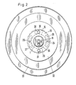
- the stops 24 and 25 of the slinger 16 each protrude into a partially circular, elongated hole-shaped opening 26 and 27 in the ring 19 (Fig. 2).
- the openings 26, 27 are of equal length and are diametrically opposite one another.
- the ring 19 is also provided with two diametrically opposed keyhole-shaped openings 28 and 29 (Fig. 2). They serve to receive screws 30, 31, which are provided on a holder 32 for the tool 33 to be clamped.
- the openings 28, 29 of the ring 19 lie, as shown in FIG. 2, centrally between the openings 26 and 27.
- the larger opening section of the opening 28 faces the opening 27 and the larger opening section of the opening 29 faces the opening 26.
- the pressure medium is introduced into the bore 9 via the filling valve 10.
- Grease is preferably used as the pressure medium, which is introduced by means of a grease gun.
- a clamping pressure of, for example, approximately 300 to 500 bar is generated once with this pressure medium.
- the clamping screw 11 is screwed in so far that it rests with its head 34 on the flat end face 35 of the spindle 2.
- the tensioning piston 13 is pressed firmly against the tensioning screw 11 under the pressure.
- the pressure medium passes through the transverse bore (s) 8 into the chamber (s) 6, as a result of which the wall sections 7 of the clamping bush 5 are elastically deformed radially outward.
- the holder 32 seated on the clamping bush 5 is centered and radially clamped with the tool 33 on the clamping bush. If the tool with the holder is to be removed, only the clamping screw 11 is loosened, as a result of which the clamping piston 13 in the bore 9 is shifted under the clamping pressure. As a result, the pressure medium is relaxed and the deformation of the wall sections 7 of the clamping bush 5 is canceled, so that the tool 33 with the holder 32 can be easily removed. If a tool is pushed onto the clamping bush 5 again, then only the clamping screw 11 is screwed back into the threaded bore 13 until its head 34 abuts the flat end face 35 of the spindle 2.
- a screw 36 which can be reached at the end and which is opened when first filled with pressure medium and thus enables ventilation when filling. Then the screw plug 36 is screwed back into its closed position shown in FIG. 1.
- the tool 33 is axially fixed and positively secured against rotation by the two screws 30 and 31 in the holder 32.
- the tool 33 is pushed onto the clamping bush 5 with the holder 32 in such a way that the screws 30, 31 through the larger sections of the keyhole-shaped openings 28 , 29 in ring 19.
- the tool 33 is rotated counter to the direction of rotation, the shanks of the screws 30, 33 in the narrower Ab cuts of the keyhole-shaped openings 28, 29 arrive.
- the screw heads are then on the back 37 of the ring 19.
- the ring 19 is taken along when the tool is turned further and is screwed further into the slinger 16 against the working direction of rotation.
- the ring 19 pulls the tool 32, 33 axially until the holder 32 rests on the end face 38 of the slinger 16. In this way, the tool 32, 33 is axially fixed and secured against the slinger 16. The ring 19 holds the tool 32, 33 in this position. Then the clamping screw 11 is tightened in the manner described and thus the clamping pressure is generated so that the axially fixed tool 32, 33 is now also radially centered and clamped.
- the ring 19 is screwed into the recess 17 of the slinger 16 so that when the ring 19 is rotated while the tool 32, 33 is being secured, it is ensured in any case that the tool also comes into contact with the end face 38 of the slinger 16.
- the stops 24, 25 designed as studs are only screwed into the slinger 16 when the tensioning device is assembled when the ring 19 is in its installed position.
- the ring 19 is screwed so far into the slinger 16 that its elongated openings 26, 27 lie in the region of the threaded holes for receiving the stops 24, 25.
- the openings 26, 27 are so long and the stops 24, 25 are arranged within the openings so that the ring 19 when the tool 32, 33 is placed can be rotated so far in any case that the tool on the end face 38 of the slingshot ring 16 comes to the plant.
- the screws 30, 31 can be adjusted axially in the holder 32 so that the distance of the screw head from the adjacent side surface 39 of the holder 32 corresponds to the thickness of the ring 19 plus a small excess for insertion.
- the tool 32, 33 is axially immovable relative to the ring 19 in the installed position.
- the ring 19 positions the tool 32, 33 axially in the manner described. Since the ring 19 is screwed into the centrifugal ring 16 during rotation, the tool 32, 33 is displaced in the axial direction, so that when the tool is in contact with the end face 38 of the centrifugal ring 16 an application force acting in the axial direction is also generated.
- the ring 19 prevents the tool 32, 33 from being pushed by the spindle 3. Since the tool 32, 33 is rotated counter to the direction of rotation of the work, if the hydraulic pressure fails, the ring 19 would reverse further into the centrifuge against the direction of rotation of the work screwed ring 16. This prevents the tool 32, 33 from being unintentionally pushed off the spindle 3.
Landscapes
- Engineering & Computer Science (AREA)
- Mechanical Engineering (AREA)
- Life Sciences & Earth Sciences (AREA)
- Physics & Mathematics (AREA)
- Fluid Mechanics (AREA)
- Wood Science & Technology (AREA)
- Forests & Forestry (AREA)
- Constituent Portions Of Griding Lathes, Driving, Sensing And Control (AREA)
- Gripping On Spindles (AREA)
- Clamps And Clips (AREA)
Priority Applications (1)
| Application Number | Priority Date | Filing Date | Title |
|---|---|---|---|
| AT89119799T ATE92825T1 (de) | 1988-10-28 | 1989-10-25 | Spannvorrichtung fuer werkzeuge, insbesondere fuer schleifscheiben. |
Applications Claiming Priority (2)
| Application Number | Priority Date | Filing Date | Title |
|---|---|---|---|
| DE8813580U DE8813580U1 (de) | 1988-10-28 | 1988-10-28 | Spannvorrichtung für Werkzeuge, insbesondere für Schleifscheiben |
| DE8813580U | 1988-10-28 |
Publications (3)
| Publication Number | Publication Date |
|---|---|
| EP0366105A2 true EP0366105A2 (fr) | 1990-05-02 |
| EP0366105A3 EP0366105A3 (fr) | 1991-03-13 |
| EP0366105B1 EP0366105B1 (fr) | 1993-08-11 |
Family
ID=6829379
Family Applications (1)
| Application Number | Title | Priority Date | Filing Date |
|---|---|---|---|
| EP89119799A Expired - Lifetime EP0366105B1 (fr) | 1988-10-28 | 1989-10-25 | Dispositif de fixation pour outil, en particulier pour meules de rectification |
Country Status (5)
| Country | Link |
|---|---|
| US (1) | US5163250A (fr) |
| EP (1) | EP0366105B1 (fr) |
| JP (1) | JPH02237765A (fr) |
| AT (1) | ATE92825T1 (fr) |
| DE (2) | DE8813580U1 (fr) |
Cited By (1)
| Publication number | Priority date | Publication date | Assignee | Title |
|---|---|---|---|---|
| DE10064163A1 (de) * | 2000-12-22 | 2002-07-11 | Wernicke & Co Gmbh | Anordnung zum lösbaren Befestigen einer Schleifscheibe oder eines Schleifscheibenpakets an einer Schleifspindel |
Families Citing this family (8)
| Publication number | Priority date | Publication date | Assignee | Title |
|---|---|---|---|---|
| JPH0768464A (ja) * | 1993-09-03 | 1995-03-14 | Hitachi Koki Co Ltd | 固定側フランジ |
| DE10361810A1 (de) * | 2003-12-30 | 2005-07-28 | Robert Bosch Gmbh | Handwerkzeugmaschine mit Spanneinrichtung |
| DK2844441T3 (en) * | 2012-04-30 | 2016-09-12 | Gea Food Solutions Germany Gmbh | Cutter blade with a safety REMOVING |
| US11577365B2 (en) * | 2019-04-05 | 2023-02-14 | Honda Motor Co., Ltd. | Systems and methods of processing a rotatable assembly |
| IT202000017344A1 (it) * | 2020-07-16 | 2022-01-16 | Scm Group Spa | Gruppo operativo per una macchina utensile e macchina utensile comprendente tale gruppo operativo. |
| CN113319601B (zh) * | 2021-06-01 | 2022-12-23 | 广东艾普升智能装备有限公司 | 一种便于更换刀具的数控机床 |
| CN115139225B (zh) * | 2022-09-01 | 2022-11-11 | 昆明尼古拉斯克雷亚机床有限公司 | 一种龙门式加工中心磨削用主轴动力控制装置 |
| CH720303A1 (de) * | 2022-12-07 | 2024-06-14 | Reishauer Ag | Vorrichtung zum Schleifen eines Werkstücks und/oder Abrichten eines Werkzeugs |
Family Cites Families (7)
| Publication number | Priority date | Publication date | Assignee | Title |
|---|---|---|---|---|
| US519892A (en) * | 1894-05-15 | Clamp for circular saws | ||
| US2616230A (en) * | 1950-07-11 | 1952-11-04 | Allison Company | Abrasive cutoff wheel |
| DE1062567B (de) * | 1958-02-11 | 1959-07-30 | Diskus Werke Frankfurt Main Ag | Spannvorrichtung zur loesbaren Befestigung von Schleifkoerpern an ihrer Tragscheibe |
| US3130978A (en) * | 1961-07-31 | 1964-04-28 | Ingersoll Milling Machine Co | Expansible mandrel |
| DE1300777B (de) * | 1965-03-03 | 1969-08-07 | Wilhelm Koenig Mechanische Wer | Hydraulischer Spanndorn |
| DE2937168A1 (de) * | 1979-09-14 | 1981-04-02 | BBT-Holding AG, Bösingen | Anschlussvorrichtung zum anschluss eines werkzeugs an eine rotierend antreibbare spindel |
| DE3512366A1 (de) * | 1985-04-04 | 1986-10-09 | Montanwerke Walter GmbH, 7400 Tübingen | Spannvorrichtung fuer eine schleifscheibe |
-
1988
- 1988-10-28 DE DE8813580U patent/DE8813580U1/de not_active Expired
-
1989
- 1989-10-25 DE DE8989119799T patent/DE58905251D1/de not_active Expired - Fee Related
- 1989-10-25 AT AT89119799T patent/ATE92825T1/de not_active IP Right Cessation
- 1989-10-25 EP EP89119799A patent/EP0366105B1/fr not_active Expired - Lifetime
- 1989-10-27 JP JP1278741A patent/JPH02237765A/ja active Pending
- 1989-10-27 US US07/428,367 patent/US5163250A/en not_active Expired - Fee Related
Cited By (3)
| Publication number | Priority date | Publication date | Assignee | Title |
|---|---|---|---|---|
| DE10064163A1 (de) * | 2000-12-22 | 2002-07-11 | Wernicke & Co Gmbh | Anordnung zum lösbaren Befestigen einer Schleifscheibe oder eines Schleifscheibenpakets an einer Schleifspindel |
| DE10064163C2 (de) * | 2000-12-22 | 2003-04-17 | Wernicke & Co Gmbh | Anordnung zum lösbaren Befestigen einer Schleifscheibe oder eines Schleifscheibenpakets an einer Schleifspindel |
| US6966824B2 (en) | 2000-12-22 | 2005-11-22 | Weco Optik Gmbh | Arrangement for detachably securing a grinding wheel or a group of grinding wheels on a wheel spindle |
Also Published As
| Publication number | Publication date |
|---|---|
| DE8813580U1 (de) | 1989-01-05 |
| ATE92825T1 (de) | 1993-08-15 |
| JPH02237765A (ja) | 1990-09-20 |
| DE58905251D1 (de) | 1993-09-16 |
| EP0366105B1 (fr) | 1993-08-11 |
| US5163250A (en) | 1992-11-17 |
| EP0366105A3 (fr) | 1991-03-13 |
Similar Documents
| Publication | Publication Date | Title |
|---|---|---|
| DE69325723T2 (de) | Gerät und methode zum balancieren drehender werkzeuge | |
| EP0433925B1 (fr) | Dispositif de serrage hydraulique | |
| DE69800037T2 (de) | Spannfutter | |
| CH656335A5 (de) | Bohrwerkzeug. | |
| WO2017162357A1 (fr) | Outil d'usinage par enlèvement de copeaux | |
| DE10359052A1 (de) | Auspreßvorrichtung für exzentrische Traggelenke | |
| EP0366105A2 (fr) | Dispositif de fixation pour outil, en particulier pour meules de rectification | |
| EP0164582A1 (fr) | Mandrin pour le montage centré de pièces en rotation | |
| DE2244938C3 (de) | Vorrichtung zum Verbinden eines Bauteils mit einer WeUe o.dgl | |
| DE3422000A1 (de) | Druckmittelbetaetigte spannvorrichtung zum spannen von werkzeugen oder werkstuecken | |
| EP0684099A1 (fr) | Outil combiné | |
| DE3517246C2 (fr) | ||
| DE4339755C1 (de) | Vorrichtung zum Einbringen von Bohrungen in eine Schüssel bzw. einer Felge eines Rades eines Kraftfahrzeuges | |
| EP2062690A1 (fr) | Dispositif de vissage pour un dispositif de vissage mécanique | |
| EP3864290B1 (fr) | Dispositif de serrage pour un dispositif de refoulement de fluide et dispositif de refoulement de fluide | |
| DE2750367C2 (de) | Werkzeughalter für Bohrer | |
| DE2854121C2 (de) | An ein Maschinenteil ansetzbare Vorrichtung zum Ausstechen von Ringlippen dort in Bohrungen eingestemmter Lagerbüchsen | |
| DE3413285A1 (de) | Spannvorrichtung fuer werkzeuge, wie bohrer, fraeser oder dgl. | |
| DE3232495A1 (de) | Vorrichtung zur kuehlmittelzufuhr zu mit kuehlmittelkanaelen versehenen, rotierenden schneidwerkzeugen fuer die spanende metallbearbeitung, insbesondere bohrwerkzeuge | |
| CH669346A5 (fr) | ||
| DE3935485A1 (de) | Spannvorrichtung fuer werkzeuge, insbesondere fuer schleifscheiben | |
| EP0598289B1 (fr) | Boulon de centrage pour la fixation, le centrage et/ou le positionnement des éléments avec des trous de centrage | |
| DE102021129551B4 (de) | Exzentrisch verstellbares Werkzeugfutter | |
| DE1204498B (de) | Mitnehmerspitze fuer Werkzeugmaschinen | |
| AT224414B (de) | Haltevorrichtung für Werkstücke, insbesondere von zylindrischer Gestalt |
Legal Events
| Date | Code | Title | Description |
|---|---|---|---|
| PUAI | Public reference made under article 153(3) epc to a published international application that has entered the european phase |
Free format text: ORIGINAL CODE: 0009012 |
|
| AK | Designated contracting states |
Kind code of ref document: A2 Designated state(s): AT BE CH DE ES FR GB GR IT LI LU NL SE |
|
| PUAL | Search report despatched |
Free format text: ORIGINAL CODE: 0009013 |
|
| AK | Designated contracting states |
Kind code of ref document: A3 Designated state(s): AT BE CH DE ES FR GB GR IT LI LU NL SE |
|
| 17P | Request for examination filed |
Effective date: 19910911 |
|
| 17Q | First examination report despatched |
Effective date: 19920520 |
|
| GRAA | (expected) grant |
Free format text: ORIGINAL CODE: 0009210 |
|
| AK | Designated contracting states |
Kind code of ref document: B1 Designated state(s): AT BE CH DE ES FR GB GR IT LI LU NL SE |
|
| PG25 | Lapsed in a contracting state [announced via postgrant information from national office to epo] |
Ref country code: SE Effective date: 19930811 Ref country code: NL Effective date: 19930811 Ref country code: GR Free format text: LAPSE BECAUSE OF FAILURE TO SUBMIT A TRANSLATION OF THE DESCRIPTION OR TO PAY THE FEE WITHIN THE PRESCRIBED TIME-LIMIT Effective date: 19930811 Ref country code: ES Free format text: THE PATENT HAS BEEN ANNULLED BY A DECISION OF A NATIONAL AUTHORITY Effective date: 19930811 |
|
| REF | Corresponds to: |
Ref document number: 92825 Country of ref document: AT Date of ref document: 19930815 Kind code of ref document: T |
|
| ET | Fr: translation filed | ||
| REF | Corresponds to: |
Ref document number: 58905251 Country of ref document: DE Date of ref document: 19930916 |
|
| PGFP | Annual fee paid to national office [announced via postgrant information from national office to epo] |
Ref country code: BE Payment date: 19931013 Year of fee payment: 5 |
|
| PG25 | Lapsed in a contracting state [announced via postgrant information from national office to epo] |
Ref country code: AT Effective date: 19931025 |
|
| PG25 | Lapsed in a contracting state [announced via postgrant information from national office to epo] |
Ref country code: LU Free format text: LAPSE BECAUSE OF NON-PAYMENT OF DUE FEES Effective date: 19931031 Ref country code: LI Effective date: 19931031 Ref country code: CH Effective date: 19931031 |
|
| ITF | It: translation for a ep patent filed | ||
| GBT | Gb: translation of ep patent filed (gb section 77(6)(a)/1977) |
Effective date: 19931026 |
|
| NLV1 | Nl: lapsed or annulled due to failure to fulfill the requirements of art. 29p and 29m of the patents act | ||
| PLBE | No opposition filed within time limit |
Free format text: ORIGINAL CODE: 0009261 |
|
| STAA | Information on the status of an ep patent application or granted ep patent |
Free format text: STATUS: NO OPPOSITION FILED WITHIN TIME LIMIT |
|
| REG | Reference to a national code |
Ref country code: CH Ref legal event code: PL |
|
| 26N | No opposition filed | ||
| PGFP | Annual fee paid to national office [announced via postgrant information from national office to epo] |
Ref country code: GB Payment date: 19940920 Year of fee payment: 6 |
|
| PGFP | Annual fee paid to national office [announced via postgrant information from national office to epo] |
Ref country code: FR Payment date: 19941027 Year of fee payment: 6 |
|
| PG25 | Lapsed in a contracting state [announced via postgrant information from national office to epo] |
Ref country code: BE Effective date: 19941031 |
|
| PGFP | Annual fee paid to national office [announced via postgrant information from national office to epo] |
Ref country code: DE Payment date: 19941215 Year of fee payment: 6 |
|
| BERE | Be: lapsed |
Owner name: MICHAEL WEINIG A.G. Effective date: 19941031 |
|
| PG25 | Lapsed in a contracting state [announced via postgrant information from national office to epo] |
Ref country code: GB Effective date: 19951025 |
|
| GBPC | Gb: european patent ceased through non-payment of renewal fee |
Effective date: 19951025 |
|
| PG25 | Lapsed in a contracting state [announced via postgrant information from national office to epo] |
Ref country code: FR Effective date: 19960628 |
|
| PG25 | Lapsed in a contracting state [announced via postgrant information from national office to epo] |
Ref country code: DE Effective date: 19960702 |
|
| REG | Reference to a national code |
Ref country code: FR Ref legal event code: ST |
|
| PG25 | Lapsed in a contracting state [announced via postgrant information from national office to epo] |
Ref country code: IT Free format text: LAPSE BECAUSE OF NON-PAYMENT OF DUE FEES;WARNING: LAPSES OF ITALIAN PATENTS WITH EFFECTIVE DATE BEFORE 2007 MAY HAVE OCCURRED AT ANY TIME BEFORE 2007. THE CORRECT EFFECTIVE DATE MAY BE DIFFERENT FROM THE ONE RECORDED. Effective date: 20051025 |