EP0366105A2 - Tool-clamping device, especially for grinding wheels - Google Patents
Tool-clamping device, especially for grinding wheels Download PDFInfo
- Publication number
- EP0366105A2 EP0366105A2 EP89119799A EP89119799A EP0366105A2 EP 0366105 A2 EP0366105 A2 EP 0366105A2 EP 89119799 A EP89119799 A EP 89119799A EP 89119799 A EP89119799 A EP 89119799A EP 0366105 A2 EP0366105 A2 EP 0366105A2
- Authority
- EP
- European Patent Office
- Prior art keywords
- clamping
- clamping device
- tool
- spindle
- axial
- Prior art date
- Legal status (The legal status is an assumption and is not a legal conclusion. Google has not performed a legal analysis and makes no representation as to the accuracy of the status listed.)
- Granted
Links
Images

Classifications
-
- B—PERFORMING OPERATIONS; TRANSPORTING
- B27—WORKING OR PRESERVING WOOD OR SIMILAR MATERIAL; NAILING OR STAPLING MACHINES IN GENERAL
- B27B—SAWS FOR WOOD OR SIMILAR MATERIAL; COMPONENTS OR ACCESSORIES THEREFOR
- B27B5/00—Sawing machines working with circular or cylindrical saw blades; Components or equipment therefor
- B27B5/29—Details; Component parts; Accessories
- B27B5/30—Details; Component parts; Accessories for mounting or securing saw blades or saw spindles
- B27B5/32—Devices for securing circular saw blades to the saw spindle
- B27B5/325—Devices for securing circular saw blades to the saw spindle using fluid pressure means
-
- B—PERFORMING OPERATIONS; TRANSPORTING
- B24—GRINDING; POLISHING
- B24B—MACHINES, DEVICES, OR PROCESSES FOR GRINDING OR POLISHING; DRESSING OR CONDITIONING OF ABRADING SURFACES; FEEDING OF GRINDING, POLISHING, OR LAPPING AGENTS
- B24B45/00—Means for securing grinding wheels on rotary arbors
Definitions
- the invention relates to a clamping device for tools, in particular for grinding wheels, according to the preamble of claim 1.
- the tool is provided with the clamping part.
- the hydraulic medium After being pushed onto the spindle, the hydraulic medium must be pressurized so that the clamping part is elastically expanded.
- the tool is clamped radially on the spindle and is also centered radially. To ensure an exact position of the tool, it is pushed onto the clamping bush up to a stop on the clamping device.
- the invention has for its object to design the generic clamping device so that it allows easy replacement of the tools, which can still be reliably clamped.
- the elastically expandable clamping part is no longer part of the tool, but is provided on the spindle.
- the tools can therefore be simple. In particular, conventional tools can now also be hydraulically clamped. If a tool is to be removed from the clamping device according to the invention, then only the clamping screw has to be screwed back into its pressure relief position. Then the tool can be easily pushed off the clamping bush. If a tool is to be clamped, it is only necessary to screw the clamping screw back into its clamping position from the pressure relief position. The pressure medium in the bore of the spindle is brought to the desired clamping pressure. This makes changing and clamping the tools very time-saving and, above all, easy.
- the tool With the axial tendon, in addition to its radial centering and clamping, the tool is also axially fixed and clamped.
- the axial tendon is positively connected to the tool in the axial direction, so that the tool can then be moved in the axial direction during the axial adjustment of the axial tendon and can be pulled, for example, against a stop surface.
- This allows the tool to be positioned correctly in the clamping device both in the radial and in the axial direction.
- the tool is therefore precisely aligned on the spindle or its clamping bush.
- the clamping device is used to clamp tools, in particular grinding wheels.
- the clamping device is provided on a machine and has a housing 1, in which a spindle 2 with roller bearings 3, 4 is rotatably mounted.
- the spindle 2 protrudes forward from the housing 1 and carries at the free end a clamping bush 5 which is designed as a hydraulic bushing and has one or more chambers 6 which are axially closed.
- the chamber 6 is delimited radially inwards by the spindle 2 and radially outwards by an elastically deformable wall section 7 of the clamping bush 5.
- At least one transverse bore 8 which penetrates the spindle 2 opens into the chamber 6 and connects the chamber 6 to a bore 9 which penetrates the spindle 2 centrally and axially.
- the clamping bush 5 is mounted on the free end of the spindle 2.
- the bore 9 is closed by a filling valve 10, via which a pressure medium is introduced into the bore 9.
- the bore 9 is closed by a clamping screw 11 which is screwed into a threaded bore 12 of the spindle 2 which is open at the end.
- a tensioning piston 13 which under the pressure of the pressure medium in the bore 9 rests with its end face on the clamping screw 11 (Fig. 1).
- the tensioning piston 13 is guided in a sealed manner in the bore 9, so that the pressure medium cannot reach the outside between the tensioning piston and the wall of the bore 9.
- the spindle 2 is provided in the area outside the housing 1 with a collar 14 which has an enlarged outer diameter and which carries an external thread 15.
- a fling ring 16 is screwed onto the collar 14 and has, on its side facing the clamping bush 5, a front-side recess 17 which is coaxial with the spindle 2 and which is provided with an internal thread 18.
- a ring 19 can be screwed into this recess 17.
- the centrifugal ring On the side opposite the recess 17, the centrifugal ring is provided with two coaxial annular depressions 20 and 21, in which the housing 1 engages with play with corresponding annular webs 22 and 23. They are also coaxial to the spindle 2.
- two stops 24 and 25 are provided diametrically opposite one another, which are preferably designed as studs. The stops 24, 25 protrude into the annular recess 17 of the slinger 16 (FIG. 1). If the stops 24, 25 are designed as screws, they can easily be attached to the slinger 16 so that they do not protrude from the recess 17.
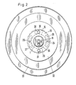
- the stops 24 and 25 of the slinger 16 each protrude into a partially circular, elongated hole-shaped opening 26 and 27 in the ring 19 (Fig. 2).
- the openings 26, 27 are of equal length and are diametrically opposite one another.
- the ring 19 is also provided with two diametrically opposed keyhole-shaped openings 28 and 29 (Fig. 2). They serve to receive screws 30, 31, which are provided on a holder 32 for the tool 33 to be clamped.
- the openings 28, 29 of the ring 19 lie, as shown in FIG. 2, centrally between the openings 26 and 27.
- the larger opening section of the opening 28 faces the opening 27 and the larger opening section of the opening 29 faces the opening 26.
- the pressure medium is introduced into the bore 9 via the filling valve 10.
- Grease is preferably used as the pressure medium, which is introduced by means of a grease gun.
- a clamping pressure of, for example, approximately 300 to 500 bar is generated once with this pressure medium.
- the clamping screw 11 is screwed in so far that it rests with its head 34 on the flat end face 35 of the spindle 2.
- the tensioning piston 13 is pressed firmly against the tensioning screw 11 under the pressure.
- the pressure medium passes through the transverse bore (s) 8 into the chamber (s) 6, as a result of which the wall sections 7 of the clamping bush 5 are elastically deformed radially outward.
- the holder 32 seated on the clamping bush 5 is centered and radially clamped with the tool 33 on the clamping bush. If the tool with the holder is to be removed, only the clamping screw 11 is loosened, as a result of which the clamping piston 13 in the bore 9 is shifted under the clamping pressure. As a result, the pressure medium is relaxed and the deformation of the wall sections 7 of the clamping bush 5 is canceled, so that the tool 33 with the holder 32 can be easily removed. If a tool is pushed onto the clamping bush 5 again, then only the clamping screw 11 is screwed back into the threaded bore 13 until its head 34 abuts the flat end face 35 of the spindle 2.
- a screw 36 which can be reached at the end and which is opened when first filled with pressure medium and thus enables ventilation when filling. Then the screw plug 36 is screwed back into its closed position shown in FIG. 1.
- the tool 33 is axially fixed and positively secured against rotation by the two screws 30 and 31 in the holder 32.
- the tool 33 is pushed onto the clamping bush 5 with the holder 32 in such a way that the screws 30, 31 through the larger sections of the keyhole-shaped openings 28 , 29 in ring 19.
- the tool 33 is rotated counter to the direction of rotation, the shanks of the screws 30, 33 in the narrower Ab cuts of the keyhole-shaped openings 28, 29 arrive.
- the screw heads are then on the back 37 of the ring 19.
- the ring 19 is taken along when the tool is turned further and is screwed further into the slinger 16 against the working direction of rotation.
- the ring 19 pulls the tool 32, 33 axially until the holder 32 rests on the end face 38 of the slinger 16. In this way, the tool 32, 33 is axially fixed and secured against the slinger 16. The ring 19 holds the tool 32, 33 in this position. Then the clamping screw 11 is tightened in the manner described and thus the clamping pressure is generated so that the axially fixed tool 32, 33 is now also radially centered and clamped.
- the ring 19 is screwed into the recess 17 of the slinger 16 so that when the ring 19 is rotated while the tool 32, 33 is being secured, it is ensured in any case that the tool also comes into contact with the end face 38 of the slinger 16.
- the stops 24, 25 designed as studs are only screwed into the slinger 16 when the tensioning device is assembled when the ring 19 is in its installed position.
- the ring 19 is screwed so far into the slinger 16 that its elongated openings 26, 27 lie in the region of the threaded holes for receiving the stops 24, 25.
- the openings 26, 27 are so long and the stops 24, 25 are arranged within the openings so that the ring 19 when the tool 32, 33 is placed can be rotated so far in any case that the tool on the end face 38 of the slingshot ring 16 comes to the plant.
- the screws 30, 31 can be adjusted axially in the holder 32 so that the distance of the screw head from the adjacent side surface 39 of the holder 32 corresponds to the thickness of the ring 19 plus a small excess for insertion.
- the tool 32, 33 is axially immovable relative to the ring 19 in the installed position.
- the ring 19 positions the tool 32, 33 axially in the manner described. Since the ring 19 is screwed into the centrifugal ring 16 during rotation, the tool 32, 33 is displaced in the axial direction, so that when the tool is in contact with the end face 38 of the centrifugal ring 16 an application force acting in the axial direction is also generated.
- the ring 19 prevents the tool 32, 33 from being pushed by the spindle 3. Since the tool 32, 33 is rotated counter to the direction of rotation of the work, if the hydraulic pressure fails, the ring 19 would reverse further into the centrifuge against the direction of rotation of the work screwed ring 16. This prevents the tool 32, 33 from being unintentionally pushed off the spindle 3.
Abstract
Description
Die Erfindung betrifft eine Spannvorrichtung für Werkzeuge, insbesondere für Schleifscheiben, nach dem Oberbegriff des Anspruches 1.The invention relates to a clamping device for tools, in particular for grinding wheels, according to the preamble of
Bei dieser bekannten Spannvorrichtung ist das Werkzeug mit dem Spannteil versehen. Nach dem Aufschieben auf die Spindel muß das Hydraulikmedium unter Druck gesetzt werden, so daß der Spannteil elastisch aufgeweitet wird. Dadurch wird das Werkzeug radial auf der Spindel gespannt und hierbei auch radial zentriert. Um eine genaue Lage des Werkzeuges sicherzustellen, wird es bis zu einem Anschlag an der Spannvorrichtung auf die Spannbuchse geschoben.In this known clamping device, the tool is provided with the clamping part. After being pushed onto the spindle, the hydraulic medium must be pressurized so that the clamping part is elastically expanded. As a result, the tool is clamped radially on the spindle and is also centered radially. To ensure an exact position of the tool, it is pushed onto the clamping bush up to a stop on the clamping device.
Der Erfindung liegt die Aufgabe zugrunde, die gattungsgemäße Spannvorrichtung so auszubilden, daß sie ein einfaches Auswechseln der Werkzeuge erlaubt, die dabei dennoch zuverlässig gespannt werden können.The invention has for its object to design the generic clamping device so that it allows easy replacement of the tools, which can still be reliably clamped.
Diese Aufgabe wird bei der gattungsgemäßen Spannvorrichtung erfindungsgemäß mit den kennzeichnenden Merkmalen des Ansprüches 1 gelöst.This object is achieved in the generic tensioning device according to the invention with the characterizing features of
Bei der erfindungsgemäßen Spanneinrichtung ist der elastisch aufweitbare Spannteil nicht mehr Teil des Werkzeuges, sondern auf der Spindel vorgesehen. Die Werkzeuge können darum einfach ausgebildet sein. Insbesondere können auch herkömmliche Werkzeuge nunmehr hydraulisch gespannt werden. Soll bei der erfindungsgemäßen Spannvorrichtung ein Werkzeug abgenommen werden, dann muß lediglich die Spannschraube in ihre Druckentlastungsstellung zurückgeschraubt werden. Dann läßt sich das Werkzeug ohne Schwierigkeiten von der Spannbuchse abschieben. Soll ein Werkzeug gespannt werden, dann ist es lediglich erforderlich, die Spannschraube aus der Druckentlastungsstellung wieder in ihre Spannstellung zurückzuschrauben. Hierbei wird das Druckmedium in der Bohrung der Spindel auf den gewünschten Spanndruck gebracht. Dadurch gestaltet sich das Auswechseln und Spannen der Werkzeuge sehr zeitsparend und vor allen Dingen auch einfach. Mit dem Axialspannglied wird das Werkzeug zusätzlich zu seiner radialen Zentrierung und Spannung durch die Spannbuchse auch axial fixiert und gespannt. Das Axialspannglied wird mit dem Werkzeug in Achsrichtung formschlüssig verbunden, so daß das Werkzeug dann bei der Axialverstellung des Axialspanngliedes in Achsrichtung verschoben und beispielsweise gegen eine Anschlagfläche gezogen werden kann. Dadurch ist eine einwandfreie Positionierung des Werkzeuges in der Spannvorrichtung sowohl in radialer als auch in axialer Richtung möglich. Das Werkzeug sitzt darum genau ausgerichtet auf der Spindel bzw. deren Spannbuchse.In the clamping device according to the invention, the elastically expandable clamping part is no longer part of the tool, but is provided on the spindle. The tools can therefore be simple. In particular, conventional tools can now also be hydraulically clamped. If a tool is to be removed from the clamping device according to the invention, then only the clamping screw has to be screwed back into its pressure relief position. Then the tool can be easily pushed off the clamping bush. If a tool is to be clamped, it is only necessary to screw the clamping screw back into its clamping position from the pressure relief position. The pressure medium in the bore of the spindle is brought to the desired clamping pressure. This makes changing and clamping the tools very time-saving and, above all, easy. With the axial tendon, in addition to its radial centering and clamping, the tool is also axially fixed and clamped. The axial tendon is positively connected to the tool in the axial direction, so that the tool can then be moved in the axial direction during the axial adjustment of the axial tendon and can be pulled, for example, against a stop surface. This allows the tool to be positioned correctly in the clamping device both in the radial and in the axial direction. The tool is therefore precisely aligned on the spindle or its clamping bush.
Weitere Merkmale der Erfindung ergeben sich aus den weiteren Ansprüchen, der Beschreibung und den Zeichnungen.Further features of the invention result from the further claims, the description and the drawings.
Die Erfindung wird anhand eines in den Zeichnungen dargestellen Ausführungsbeispieles näher erläutert. Es zeigen
- Fig. 1 in schematischer Darstellung und im Axialschnitt eine erfindungsgemäße Spanneinrichtung,
- Fig. 2 eine Stirnansicht der Spannvorrichtung.
- 1 is a schematic representation and in axial section of a tensioning device according to the invention,
- Fig. 2 is an end view of the tensioning device.
Die Spanneinrichtung dient zum Spannen von Werkzeugen, insbesondere von Schleifscheiben. Die Spanneinrichtung ist an einer Maschine vorgesehen und hat ein Gehäuse 1, in dem eine Spindel 2 mit Wälzlagern 3, 4 drehbar gelagert ist. Die Spindel 2 ragt nach vorne aus dem Gehäuse 1 und trägt am freien Ende eine Spannbuchse 5, die als Hydrobuchse ausgebildet ist und eine oder mehrere Kammern 6 aufweist, die axial geschlossen sind. Radial nach innen wird die Kammer 6 durch die Spindel 2 und radial nach außen durch einen elastisch verformbaren Wandabschnitt 7 der Spannbuchse 5 begrenzt. In die Kammer 6 mündet mindestens eine die Spindel 2 durchsetzende Querbohrung 8, welche die Kammer 6 mit einer die Spindel 2 zentral und axial durchsetzenden Bohrung 9 verbindet. Die Spannbuchse 5 ist auf dem freien Ende der Spindel 2 gelagert. Die Bohrung 9 ist durch ein Füllventil 10 geschlossen, über das ein Druckmedium in die Bohrung 9 eingebracht wird.The clamping device is used to clamp tools, in particular grinding wheels. The clamping device is provided on a machine and has a
Am gegenüberliegenden Ende ist die Bohrung 9 durch eine Spannschraube 11 verschlossen, die in eine stirnseitig offene Gewindebohrung 12 der Spindel 2 geschraubt ist. In der Bohrung 9 befindet sich ein Spannkolben 13, der unter dem Druck des Druckmediums in der Bohrung 9 mit seiner Stirnseite an der Spannschraube 11 anliegt (Fig. 1). Der Spannkolben 13 ist abgedichtet in der Bohrung 9 geführt, so daß das Druckmedium nicht zwischen dem Spannkolben und der Wandung der Bohrung 9 nach außen gelangen kann.At the opposite end, the bore 9 is closed by a
Im Bereich zwischen der Spannbuchse 5 und dem Wälzlager 4 ist die Spindel 2 im Bereich außerhalb des Gehäuses 1 mit einem im Außendurchmesser vergrößerten Bund 14 versehen, der Außengewinde 15 trägt. Auf den Bund 14 ist ein Schleuderring 16 geschraubt, der auf seiner der Spannbuchse 5 zugewandten Seite eine koaxial zur Spindel 2 liegende stirnseitige Ausnehmung 17 aufweist, die mit einem Innengewinde 18 versehen ist. In diese Ausnehmung 17 kann ein Ring 19 geschraubt werden.In the area between the clamping bush 5 and the roller bearing 4, the
Auf der der Ausnehmung 17 gegenüberliegenden Seite ist der Schleudering mit zwei koaxialen ringförmigen Vertiefungen 20 und 21 versehen, in die das Gehäuse 1 mit entsprechenden ringförmigen Stegen 22 und 23 mit Spiel eingreift. Sie liegen ebenfalls koaxial zur Spindel 2. Im Schleudering 16 sind diametral einander gegenüberliegend zwei Anschläge 24 und 25 vorgesehen, die vorzugsweise als Stiftschrauben ausgebildet sind. Die Anschläge 24, 25 ragen in die ringförmige Ausnehmung 17 des Schleuderringes 16 (Fig. 1). Wenn die Anschläge 24, 25 als Schrauben ausgebildet sind, lassen sie sich leicht so am Schleuderring 16 anbringen, daß sie nicht aus der Ausnehmung 17 ragen.On the side opposite the
Die Anschläge 24 und 25 des Schleuderringes 16 ragen jeweils in eine teilkreisförmig gekrümmte langlochförmige Öffnung 26 und 27 im Ring 19 (Fig. 2). Die Öffnungen 26, 27 sind gleich lang und liegen diametral einander gegenüber.The
Der Ring 19 ist außerdem mit zwei diametral einander gegenüberliegenden schlüssellochförmigen Durchbrüchen 28 und 29 versehen (Fig. 2). Sie dienen zur Aufnahme von Schrauben 30, 31, die an einem Halter 32 für das zu spannende Werkzeug 33 vorgesehen sind.The
Die Durchbrüche 28, 29 des Ringes 19 liegen, wie Fig. 2 zeigt, mittig zwischen den Öffnungen 26 und 27. Dabei ist der größere Öffnungsabschnitt des Durchbruches 28 der Öffnung 27 und der größere Öffnungsabschnitt des Durchbruches 29 der Öffnung 26 zugewandt.The
Zur Inbetriebnahme der Spannvorrichtung wird über das Füllventil 10 das Druckmedium in die Bohrung 9 eingebracht. Bevorzugt wird hierbei als Druckmedium Fett verwendet, das mittels einer Fettpresse eingebracht wird. Mit diesem Druckmedium wird ein Spanndruck von beispielsweise etwa 300 bis 500 bar einmalig erzeugt. Beim Befüllen der Bohrung 9 ist die Spannschraube 11 so weit eingeschraubt, daß sie mit ihrem Kopf 34 an der planen Stirnseite 35 der Spindel 2 anliegt. Der Spannkolben 13 wird unter dem Druck fest gegen die Spannschraube 11 gedrückt. Das Druckmedium gelangt über die Querbohrung(en) 8 in die Kammer(n) 6, wodurch die Wandabschnitte 7 der Spannbuchse 5 radial nach außen elastisch verformt werden. Auf diese Weise wird der auf der Spannbuchse 5 sitzende Halter 32 mit dem Werkzeug 33 auf der Spannbuchse zentriert und radial gespannt. Soll das Werkzeug mit dem Halter abgenommen werden, wird lediglich die Spannschraube 11 gelöst, wodurch der Spannkolben 13 in der Bohrung 9 unter dem Spanndruck verschoben wird. Dadurch wird das Druckmedium entspannt und die Verformung der Wandabschnitte 7 der Spannbuchse 5 aufhoben, so daß das Werkzeug 33 mit dem Halter 32 leicht abgenommen werden kann. Wird auf die Spannbuchse 5 wieder ein Werkzeug geschoben, dann wird lediglich die Spannschraube 11 wieder in die Gewindebohrung 13 so weit geschraubt, bis sie mit ihrem Kopf 34 an der planen Stirnseite 35 der Spindel 2 anliegt. Beim Einschrauben wird der Spannkolben 13 wieder in der Bohrung 9 zurückbewegt, wodurch sich wieder der eingangs eingestellte Spanndruck ergibt. Es ist nicht mehr notwendig, bei jedem Werkzeugwechsel über das Füllventil 10 den Spanndruck aufzubauen. Dieser wird vielmehr nur beim Befüllen mit dem Druckmedium eingestellt; alle weiteren Spannvorgänge erfolgen dann lediglich noch durch Einschrauben der Spannschraube 11 in der beschriebenen Weise.To start up the tensioning device, the pressure medium is introduced into the bore 9 via the
In der Spindel 2 ist eine stirnseitig erreichbare Verschlußschraube 36 vorgesehen, die bei der Erstfüllung mit Druckmedium geöffnet ist und somit eine Entlüftung beim Füllen ermöglicht. Anschließend wird die Verschlußschraube 36 wieder in ihre in Fig. 1 dargestellte Schließlage zurückgeschraubt.Provided in the
Die axiale Fixierung und formschlüssige Verdrehsicherung des Werkzeuges 33 erfolgt durch die beiden Schrauben 30 und 31 im Halter 32. Das Werkzeug 33 wird mit dem Halter 32 so auf die Spannbuchse 5 aufgeschoben, daß die Schrauben 30, 31 durch die größeren Abschnitte der schlüssellochförmigen Durchbrüche 28, 29 im Ring 19 gelangen. Anschließend wird das Werkzeug 33 entgegen Arbeitsdrehrichtung gedreht, wobei die Schäfte der Schrauben 30, 33 in die schmaleren Ab schnitte der schlüssellochförmigen Durchbrüche 28, 29 gelangen. Die Schraubenköpfe liegen dann an der Rückseite 37 des Ringes 19 an. Sobald die Schäfte der Schrauben 30, 31 am Rand der schlüssellochförmigen Durchbrüche 28, 29 zur Anlage kommen, wird beim weiteren Verdrehen des Werkzeuges der Ring 19 mitgenommen und weiter in den Schleuderring 16 entgegen Arbeitsdrehrichtung geschraubt. Hierbei zieht der Ring 19 das Werkzeug 32, 33 axial so weit, bis der Halter 32 an der Stirnseite 38 des Schleuderringes 16 anliegt. Das Werkzeug 32, 33 wird auf diese Weise axial fest gegen den Schleuderring 16 angelegt und gesichert. Der Ring 19 hält das Werkzeug 32, 33 in dieser Position fest. Anschließend wird die Spannschraube 11 in der beschriebenen Weise angezogen und somit der Spanndruck erzeugt, so daß das axial fixierte Werkzeug 32, 33 nunmehr auch radial zentriert und gespannt wird.The
Der Ring 19 ist so in die Ausnehmung 17 des Schleuderringes 16 geschraubt, daß beim Drehen des Ringes 19 während des Befestigens des Werkzeuges 32, 33 auf jeden Fall sichergestellt ist, daß das Werkzeug auch an der Stirnseite 38 des Schleuderringes 16 zur Anlage kommt. Die als Stiftschrauben ausgebildeten Anschläge 24, 25 werden bei der Montage der Spannvorrichtung erst dann in den Schleuderring 16 geschraubt, wenn der Ring 19 seine Einbaulage einnimmt. Hierbei wird der Ring 19 so weit in den Schleuderring 16 geschraubt, daß seine langlochförmigen Öffnungen 26, 27 im Bereich der Gewindebohrungen zur Aufnahme der Anschläge 24, 25 liegen. Die Öffnungen 26, 27 sind so lang und die Anschläge 24, 25 innerhalb der Öffnungen so angeordnet, daß der Ring 19 beim Aufsetzen des Werkzeuges 32, 33 auf jeden Fall so weit gedreht werden kann, daß das Werkzeug an der Stirnseite 38 des Schleuder ringes 16 zur Anlage kommt.The
Die Schrauben 30, 31 lassen sich im Halter 32 genau axial so einstellen, daß der Abstand des Schraubenkopfes von der benachbarten Seitenfläche 39 des Halters 32 der Dicke des Ringes 19 plus einem geringen Übermaß zum Einführen entspricht. Nach Drehen des Ringes 19 auf dem Gewinde 18 ist das Werkzeug 32, 33 gegenüber dem Ring 19 in der Einbaulage axial unverschieblich.The
Zum Abnehmen wird das Werkzeug 32, 33 und der Ring 19 nach dem Lösen der Spannschraube 11 so weit zurückgedreht, daß die Anschläge 24, 25 am entsprechenden Rand der langlochförmigen Öffnungen 26, 27 im Ring 19 zur Anlage kommen. Das Werkzeug kann dann abgenommen werden, wobei die Köpfe der Schrauben 30, 31 durch die größeren Abschnitte der schlüssellochförmigen Durchbrüche 28, 29 im Ring 19 gezogen werden können.To remove the
Der Ring 19 positioniert das Werkzeug 32, 33 in der beschriebenen Weise axial. Da beim Drehen der Ring 19 in den Schleudering 16 geschraubt wird, wird das Werkzeug 32, 33 in axialer Richtung verschoben, so daß bei der Anlage des Werkzeuges an der Stirnseite 38 des Schleuderringes 16 auch eine in axialer Richtung wirkende Anlegekraft erzeugt wird.The
Der Ring 19 verhindert bei einem evtl. Ausfall des Druckes, daß das Werkzeug 32, 33 von der Spindel 3 geschoben wird. Da das Werkzeug 32, 33 entgegen Arbeitsdrehrichtung gedreht wird, würde bei einem Ausfall des Hydraulikdruckes der Ring 19 entgegen Arbeitsdrehrichtung noch weiter in den Schleuder ring 16 geschraubt. Auf diese Weise wird verhindert, daß das Werkzeug 32, 33 unbeabsichtigt von der Spindel 3 geschoben werden kann.In the event of a pressure failure, the
Claims (16)
dadurch gekennzeichnet, daß die Spannschraube (11) in eine stirnseitige Gewindebohrung (12) der Spindel (2) geschraubt ist.2. Clamping device according to claim 1,
characterized in that the clamping screw (11) is screwed into an end threaded bore (12) of the spindle (2).
dadurch gekennzeichnet, daß in der Bohrung (9) ein Spannkolben (13) liegt, der unter dem Druck des Hydraulikmediums an der Spannschraube (11) anliegt.3. Clamping device according to claim 1 or 2,
characterized in that in the bore (9) there is a tensioning piston (13) which bears against the tensioning screw (11) under the pressure of the hydraulic medium.
dadurch gekennzeichnet, daß der Spannkolben (4) dichtend in der Bohrung (9) geführt ist.4. Clamping device according to claim 3,
characterized in that the tensioning piston (4) is sealingly guided in the bore (9).
dadurch gekennzeichnet, daß das Axialsicherungsglied (19) ein Ring ist, der Formschlußöffnungen (28, 29) für Formschlußglieder (30, 31) des Werkzeuges (32, 33) aufweist.5. Clamping device according to one of claims 1 to 4,
characterized in that the axial securing member (19) is a ring which has form-fitting openings (28, 29) for form-fitting members (30, 31) of the tool (32, 33).
dadurch gekennzeichnet, daß die Formschlußöffnungen (28, 29) schlüssellochförmig ausgebildet sind.6. Clamping device according to claim 5,
characterized in that the interlocking openings (28, 29) are keyhole-shaped.
dadurch gekennzeichnet, daß die Formschlußglieder (30, 31) axial vom Werkzeug (32, 33) abstehende Schrauben sind, welche durch die Formschlußöffnungen (28, 29) des Axialspanngliedes (19) ragen.7. Clamping device according to claim 5 or 6,
characterized in that the interlocking members (30, 31) are screws projecting axially from the tool (32, 33) and projecting through the interlocking openings (28, 29) of the axial clamping member (19).
dadurch gekennzeichnet, daß die Formschlußöffnungen (28, 29) diametral einander gegenüberliegen.8. Clamping device according to one of claims 5 to 7,
characterized in that the interlocking openings (28, 29) lie diametrically opposite one another.
dadurch gekennzeichnet, daß das Axialspannglied (19) in einen Aufnahmeteil (16) der Spannvorrichtung schraubbar ist.9. Clamping device according to one of claims 1 to 8,
characterized in that the axial tensioning member (19) can be screwed into a receiving part (16) of the tensioning device.
dadurch gekennzeichnet, daß der Aufnahmeteil (16) ein Schleuderring ist, der in seiner Stirnseite (38) eine Ausnehmung (17) zur Aufnahme des Axialspanngliedes (19) aufweist.10. Clamping device according to claim 9,
characterized in that the receiving part (16) is a slinger that has a recess (17) in its end face (38) for receiving the axial tensioning member (19).
dadurch gekennzeichnet, daß das Axialspannglied (19) begrenzt gegenüber dem Aufnahmeteil (16) drehbar ist.11. Clamping device according to one of claims 1 to 10,
characterized in that the axial tensioning member (19) is rotatable to a limited extent with respect to the receiving part (16).
dadurch gekennzeichnet, daß das Axialspannglied (19) vorzugsweise diametral einander gegenüberliegende Öffnungen (26, 27) aufweist, in die Anschläge (24, 25) des Aufnahmeteiles (16) ragen.12. Clamping device according to claim 11,
characterized in that the axial tensioning member (19) preferably has diametrically opposite openings (26, 27) into which stops (24, 25) of the receiving part (16) project.
dadurch gekennzeichnet, daß die Öffnungen (26, 27) teilkreisförmig gekrümmte Langlöcher sind.13. Clamping device according to claim 12,
characterized in that the openings (26, 27) are elongated holes which are curved in the shape of a part circle.
dadurch gekennzeichnet, daß die Anschläge (24, 25) axial zur Spindel (2) verlaufende Schrauben sind.14. Clamping device according to claim 12 or 13,
characterized in that the stops (24, 25) are screws extending axially to the spindle (2).
dadurch gekennzeichnet, daß das Werkzeug (32, 33) durch das Axialspannglied (19) gegen eine Anschlagfläche (38) gezogen ist.15. Clamping device according to one of claims 1 to 14,
characterized in that the tool (32, 33) is pulled by the axial clamping member (19) against a stop surface (38).
dadurch gekennzeichnet, daß die Anschlagfläche (38) die Stirnseite des Aufnahmeteiles (16) ist.16. Clamping device according to claim 15,
characterized in that the stop surface (38) is the end face of the receiving part (16).
Priority Applications (1)
| Application Number | Priority Date | Filing Date | Title |
|---|---|---|---|
| AT89119799T ATE92825T1 (en) | 1988-10-28 | 1989-10-25 | CLAMPING DEVICE FOR TOOLS, ESPECIALLY FOR GRINDING WHEELS. |
Applications Claiming Priority (2)
| Application Number | Priority Date | Filing Date | Title |
|---|---|---|---|
| DE8813580U DE8813580U1 (en) | 1988-10-28 | 1988-10-28 | |
| DE8813580U | 1988-10-28 |
Publications (3)
| Publication Number | Publication Date |
|---|---|
| EP0366105A2 true EP0366105A2 (en) | 1990-05-02 |
| EP0366105A3 EP0366105A3 (en) | 1991-03-13 |
| EP0366105B1 EP0366105B1 (en) | 1993-08-11 |
Family
ID=6829379
Family Applications (1)
| Application Number | Title | Priority Date | Filing Date |
|---|---|---|---|
| EP89119799A Expired - Lifetime EP0366105B1 (en) | 1988-10-28 | 1989-10-25 | Tool-clamping device, especially for grinding wheels |
Country Status (5)
| Country | Link |
|---|---|
| US (1) | US5163250A (en) |
| EP (1) | EP0366105B1 (en) |
| JP (1) | JPH02237765A (en) |
| AT (1) | ATE92825T1 (en) |
| DE (2) | DE8813580U1 (en) |
Cited By (1)
| Publication number | Priority date | Publication date | Assignee | Title |
|---|---|---|---|---|
| DE10064163A1 (en) * | 2000-12-22 | 2002-07-11 | Wernicke & Co Gmbh | Arrangement for releasably attaching a grinding wheel or a grinding wheel package to a grinding spindle |
Families Citing this family (7)
| Publication number | Priority date | Publication date | Assignee | Title |
|---|---|---|---|---|
| JPH0768464A (en) * | 1993-09-03 | 1995-03-14 | Hitachi Koki Co Ltd | Fixing side flange |
| DE10361810A1 (en) * | 2003-12-30 | 2005-07-28 | Robert Bosch Gmbh | Hand tool with clamping device |
| CN104428110A (en) * | 2012-04-30 | 2015-03-18 | Gea食品策划德国股份有限公司 | Cutting blade comprising a securing cavity |
| US11577365B2 (en) * | 2019-04-05 | 2023-02-14 | Honda Motor Co., Ltd. | Systems and methods of processing a rotatable assembly |
| IT202000017344A1 (en) * | 2020-07-16 | 2022-01-16 | Scm Group Spa | OPERATING GROUP FOR A MACHINE TOOL AND MACHINE TOOL INCLUDING THIS OPERATING GROUP. |
| CN113319601B (en) * | 2021-06-01 | 2022-12-23 | 广东艾普升智能装备有限公司 | Digit control machine tool convenient to change cutter |
| CN115139225B (en) * | 2022-09-01 | 2022-11-11 | 昆明尼古拉斯克雷亚机床有限公司 | Main shaft power control device for grinding of gantry machining center |
Citations (3)
| Publication number | Priority date | Publication date | Assignee | Title |
|---|---|---|---|---|
| DE1062567B (en) * | 1958-02-11 | 1959-07-30 | Diskus Werke Frankfurt Main Ag | Clamping device for the detachable fastening of grinding tools on your support disk |
| DE1300777B (en) * | 1965-03-03 | 1969-08-07 | Wilhelm Koenig Mechanische Wer | Hydraulic mandrel |
| DE2937168A1 (en) * | 1979-09-14 | 1981-04-02 | BBT-Holding AG, Bösingen | Drill tool connector to rotary spindle - comprises flat plates on connector and tool with mating faces at right angles to spindle |
Family Cites Families (4)
| Publication number | Priority date | Publication date | Assignee | Title |
|---|---|---|---|---|
| US519892A (en) * | 1894-05-15 | Clamp for circular saws | ||
| US2616230A (en) * | 1950-07-11 | 1952-11-04 | Allison Company | Abrasive cutoff wheel |
| US3130978A (en) * | 1961-07-31 | 1964-04-28 | Ingersoll Milling Machine Co | Expansible mandrel |
| DE3512366A1 (en) * | 1985-04-04 | 1986-10-09 | Montanwerke Walter GmbH, 7400 Tübingen | CLAMPING DEVICE FOR A GRINDING WHEEL |
-
1988
- 1988-10-28 DE DE8813580U patent/DE8813580U1/de not_active Expired
-
1989
- 1989-10-25 AT AT89119799T patent/ATE92825T1/en not_active IP Right Cessation
- 1989-10-25 EP EP89119799A patent/EP0366105B1/en not_active Expired - Lifetime
- 1989-10-25 DE DE8989119799T patent/DE58905251D1/en not_active Expired - Fee Related
- 1989-10-27 US US07/428,367 patent/US5163250A/en not_active Expired - Fee Related
- 1989-10-27 JP JP1278741A patent/JPH02237765A/en active Pending
Patent Citations (3)
| Publication number | Priority date | Publication date | Assignee | Title |
|---|---|---|---|---|
| DE1062567B (en) * | 1958-02-11 | 1959-07-30 | Diskus Werke Frankfurt Main Ag | Clamping device for the detachable fastening of grinding tools on your support disk |
| DE1300777B (en) * | 1965-03-03 | 1969-08-07 | Wilhelm Koenig Mechanische Wer | Hydraulic mandrel |
| DE2937168A1 (en) * | 1979-09-14 | 1981-04-02 | BBT-Holding AG, Bösingen | Drill tool connector to rotary spindle - comprises flat plates on connector and tool with mating faces at right angles to spindle |
Cited By (3)
| Publication number | Priority date | Publication date | Assignee | Title |
|---|---|---|---|---|
| DE10064163A1 (en) * | 2000-12-22 | 2002-07-11 | Wernicke & Co Gmbh | Arrangement for releasably attaching a grinding wheel or a grinding wheel package to a grinding spindle |
| DE10064163C2 (en) * | 2000-12-22 | 2003-04-17 | Wernicke & Co Gmbh | Arrangement for releasably attaching a grinding wheel or a grinding wheel package to a grinding spindle |
| US6966824B2 (en) | 2000-12-22 | 2005-11-22 | Weco Optik Gmbh | Arrangement for detachably securing a grinding wheel or a group of grinding wheels on a wheel spindle |
Also Published As
| Publication number | Publication date |
|---|---|
| DE58905251D1 (en) | 1993-09-16 |
| DE8813580U1 (en) | 1989-01-05 |
| EP0366105B1 (en) | 1993-08-11 |
| US5163250A (en) | 1992-11-17 |
| EP0366105A3 (en) | 1991-03-13 |
| JPH02237765A (en) | 1990-09-20 |
| ATE92825T1 (en) | 1993-08-15 |
Similar Documents
| Publication | Publication Date | Title |
|---|---|---|
| EP0433925B1 (en) | Hydraulic clamping device | |
| DE102013012765A1 (en) | Spindle unit for a machining device with a spindle lock | |
| WO2017162357A1 (en) | Cutting tool | |
| DE4230941C2 (en) | Clamping device for fastening a high part, preferably a hollow shaft, on a shaft | |
| EP0366105B1 (en) | Tool-clamping device, especially for grinding wheels | |
| DE3422000A1 (en) | PRESSURE-OPERATED CLAMPING DEVICE FOR CLAMPING TOOLS OR WORKPIECES | |
| DE2244938C3 (en) | Device for connecting a component with a WeUe or the like | |
| DE10359052A1 (en) | Automotive wheel bearing replacement axle pressure jig involves expelling drive shaft from bearing by power-press with locating dome | |
| DE8427440U1 (en) | Turret head for a lathe and matching tool holder | |
| EP0630721B1 (en) | Hydraulic clamping device | |
| DE3517246C2 (en) | ||
| EP0164582A1 (en) | Mounting device for centred mounting of rotating parts | |
| EP3864290B1 (en) | Clamping device for a device for conveying fluid, and device for conveying fluid | |
| EP2062690A1 (en) | Screw device for a mechanical screw device | |
| DE4339755C1 (en) | Arrangement for making holes in a dish or a rim of a wheel of a motor vehicle | |
| DE2854121C2 (en) | A device that can be attached to a machine part for cutting out ring lips in bearing bushes mortised in bores there | |
| DE3316283C2 (en) | Deep drilling machine | |
| CH618661A5 (en) | Clamping mandrel for clamping a film roll | |
| DE3935485A1 (en) | Hydraulic chuck for grinding wheel | |
| DE3413285A1 (en) | CLAMPING DEVICE FOR TOOLS LIKE DRILLING, MILLING OR THE LIKE | |
| DE1919438A1 (en) | Quickly exchangeable chuck | |
| CH669346A5 (en) | ||
| DE3432279C2 (en) | ||
| DE3232495A1 (en) | DEVICE FOR THE COOLANT SUPPLY TO ROTATING CUTTING TOOLS PROVIDED WITH COOLANT CHANNELS FOR THE CUTTING METAL WORKING, IN PARTICULAR DRILLING TOOLS | |
| EP0598289B1 (en) | Bolt-like locating element for the fixing, centring and/or positioning of parts with centring holes |
Legal Events
| Date | Code | Title | Description |
|---|---|---|---|
| PUAI | Public reference made under article 153(3) epc to a published international application that has entered the european phase |
Free format text: ORIGINAL CODE: 0009012 |
|
| AK | Designated contracting states |
Kind code of ref document: A2 Designated state(s): AT BE CH DE ES FR GB GR IT LI LU NL SE |
|
| PUAL | Search report despatched |
Free format text: ORIGINAL CODE: 0009013 |
|
| AK | Designated contracting states |
Kind code of ref document: A3 Designated state(s): AT BE CH DE ES FR GB GR IT LI LU NL SE |
|
| 17P | Request for examination filed |
Effective date: 19910911 |
|
| 17Q | First examination report despatched |
Effective date: 19920520 |
|
| GRAA | (expected) grant |
Free format text: ORIGINAL CODE: 0009210 |
|
| AK | Designated contracting states |
Kind code of ref document: B1 Designated state(s): AT BE CH DE ES FR GB GR IT LI LU NL SE |
|
| PG25 | Lapsed in a contracting state [announced via postgrant information from national office to epo] |
Ref country code: SE Effective date: 19930811 Ref country code: NL Effective date: 19930811 Ref country code: GR Free format text: LAPSE BECAUSE OF FAILURE TO SUBMIT A TRANSLATION OF THE DESCRIPTION OR TO PAY THE FEE WITHIN THE PRESCRIBED TIME-LIMIT Effective date: 19930811 Ref country code: ES Free format text: THE PATENT HAS BEEN ANNULLED BY A DECISION OF A NATIONAL AUTHORITY Effective date: 19930811 |
|
| REF | Corresponds to: |
Ref document number: 92825 Country of ref document: AT Date of ref document: 19930815 Kind code of ref document: T |
|
| ET | Fr: translation filed | ||
| REF | Corresponds to: |
Ref document number: 58905251 Country of ref document: DE Date of ref document: 19930916 |
|
| PGFP | Annual fee paid to national office [announced via postgrant information from national office to epo] |
Ref country code: BE Payment date: 19931013 Year of fee payment: 5 |
|
| PG25 | Lapsed in a contracting state [announced via postgrant information from national office to epo] |
Ref country code: AT Effective date: 19931025 |
|
| PG25 | Lapsed in a contracting state [announced via postgrant information from national office to epo] |
Ref country code: LU Free format text: LAPSE BECAUSE OF NON-PAYMENT OF DUE FEES Effective date: 19931031 Ref country code: LI Effective date: 19931031 Ref country code: CH Effective date: 19931031 |
|
| ITF | It: translation for a ep patent filed |
Owner name: STUDIO JAUMANN |
|
| GBT | Gb: translation of ep patent filed (gb section 77(6)(a)/1977) |
Effective date: 19931026 |
|
| NLV1 | Nl: lapsed or annulled due to failure to fulfill the requirements of art. 29p and 29m of the patents act | ||
| PLBE | No opposition filed within time limit |
Free format text: ORIGINAL CODE: 0009261 |
|
| STAA | Information on the status of an ep patent application or granted ep patent |
Free format text: STATUS: NO OPPOSITION FILED WITHIN TIME LIMIT |
|
| REG | Reference to a national code |
Ref country code: CH Ref legal event code: PL |
|
| 26N | No opposition filed | ||
| PGFP | Annual fee paid to national office [announced via postgrant information from national office to epo] |
Ref country code: GB Payment date: 19940920 Year of fee payment: 6 |
|
| PGFP | Annual fee paid to national office [announced via postgrant information from national office to epo] |
Ref country code: FR Payment date: 19941027 Year of fee payment: 6 |
|
| PG25 | Lapsed in a contracting state [announced via postgrant information from national office to epo] |
Ref country code: BE Effective date: 19941031 |
|
| PGFP | Annual fee paid to national office [announced via postgrant information from national office to epo] |
Ref country code: DE Payment date: 19941215 Year of fee payment: 6 |
|
| BERE | Be: lapsed |
Owner name: MICHAEL WEINIG A.G. Effective date: 19941031 |
|
| PG25 | Lapsed in a contracting state [announced via postgrant information from national office to epo] |
Ref country code: GB Effective date: 19951025 |
|
| GBPC | Gb: european patent ceased through non-payment of renewal fee |
Effective date: 19951025 |
|
| PG25 | Lapsed in a contracting state [announced via postgrant information from national office to epo] |
Ref country code: FR Effective date: 19960628 |
|
| PG25 | Lapsed in a contracting state [announced via postgrant information from national office to epo] |
Ref country code: DE Effective date: 19960702 |
|
| REG | Reference to a national code |
Ref country code: FR Ref legal event code: ST |
|
| PG25 | Lapsed in a contracting state [announced via postgrant information from national office to epo] |
Ref country code: IT Free format text: LAPSE BECAUSE OF NON-PAYMENT OF DUE FEES;WARNING: LAPSES OF ITALIAN PATENTS WITH EFFECTIVE DATE BEFORE 2007 MAY HAVE OCCURRED AT ANY TIME BEFORE 2007. THE CORRECT EFFECTIVE DATE MAY BE DIFFERENT FROM THE ONE RECORDED. Effective date: 20051025 |