EP0366104B1 - Dispositif de transport sous la forme d'une station d'envoi de matières pulvérulentes ou poudreuses - Google Patents
Dispositif de transport sous la forme d'une station d'envoi de matières pulvérulentes ou poudreuses Download PDFInfo
- Publication number
- EP0366104B1 EP0366104B1 EP89119791A EP89119791A EP0366104B1 EP 0366104 B1 EP0366104 B1 EP 0366104B1 EP 89119791 A EP89119791 A EP 89119791A EP 89119791 A EP89119791 A EP 89119791A EP 0366104 B1 EP0366104 B1 EP 0366104B1
- Authority
- EP
- European Patent Office
- Prior art keywords
- nozzle
- conveyed
- tubular element
- gas
- feed device
- Prior art date
- Legal status (The legal status is an assumption and is not a legal conclusion. Google has not performed a legal analysis and makes no representation as to the accuracy of the status listed.)
- Expired - Lifetime
Links
- 239000000463 material Substances 0.000 title claims abstract description 105
- 238000005243 fluidization Methods 0.000 claims abstract description 12
- 230000005484 gravity Effects 0.000 claims description 6
- 238000007789 sealing Methods 0.000 claims description 3
- 238000011144 upstream manufacturing Methods 0.000 claims description 3
- 230000001133 acceleration Effects 0.000 abstract description 6
- 238000010276 construction Methods 0.000 abstract 1
- 230000001413 cellular effect Effects 0.000 description 6
- 239000000203 mixture Substances 0.000 description 6
- 239000013590 bulk material Substances 0.000 description 4
- 230000006835 compression Effects 0.000 description 4
- 238000007906 compression Methods 0.000 description 4
- 238000013461 design Methods 0.000 description 4
- 238000012549 training Methods 0.000 description 4
- 238000004090 dissolution Methods 0.000 description 3
- 230000000694 effects Effects 0.000 description 3
- 238000004519 manufacturing process Methods 0.000 description 3
- 238000000034 method Methods 0.000 description 3
- 238000005299 abrasion Methods 0.000 description 2
- 238000000889 atomisation Methods 0.000 description 2
- 230000007812 deficiency Effects 0.000 description 2
- 239000003380 propellant Substances 0.000 description 2
- 238000009423 ventilation Methods 0.000 description 2
- 238000013022 venting Methods 0.000 description 2
- 238000009825 accumulation Methods 0.000 description 1
- 230000005540 biological transmission Effects 0.000 description 1
- 238000007664 blowing Methods 0.000 description 1
- 239000000109 continuous material Substances 0.000 description 1
- 230000003247 decreasing effect Effects 0.000 description 1
- 230000007547 defect Effects 0.000 description 1
- 238000011161 development Methods 0.000 description 1
- 239000000428 dust Substances 0.000 description 1
- 239000012530 fluid Substances 0.000 description 1
- 238000007654 immersion Methods 0.000 description 1
- 238000009434 installation Methods 0.000 description 1
- 239000002245 particle Substances 0.000 description 1
- 230000002093 peripheral effect Effects 0.000 description 1
- 239000011148 porous material Substances 0.000 description 1
- 238000005488 sandblasting Methods 0.000 description 1
- 239000010801 sewage sludge Substances 0.000 description 1
- 239000010802 sludge Substances 0.000 description 1
- 125000006850 spacer group Chemical group 0.000 description 1
- 230000003068 static effect Effects 0.000 description 1
- 239000011345 viscous material Substances 0.000 description 1
Images


Classifications
-
- B—PERFORMING OPERATIONS; TRANSPORTING
- B65—CONVEYING; PACKING; STORING; HANDLING THIN OR FILAMENTARY MATERIAL
- B65G—TRANSPORT OR STORAGE DEVICES, e.g. CONVEYORS FOR LOADING OR TIPPING, SHOP CONVEYOR SYSTEMS OR PNEUMATIC TUBE CONVEYORS
- B65G53/00—Conveying materials in bulk through troughs, pipes or tubes by floating the materials or by flow of gas, liquid or foam
- B65G53/34—Details
- B65G53/40—Feeding or discharging devices
- B65G53/42—Nozzles
Definitions
- the invention relates to a conveyor device in the form of a transmitter for dusty or fine-grained goods for transport in conveyor lines with a gas, in particular air, as a conveyor, the transmitter being designed as a pipe element connected upstream of a conveyor line, and wherein the gas is the material to be transported is supplied in the area of an inlet of the tubular element via an associated nozzle and a seal can be carried out in front of the inlet by the flowing material, the tubular element having an integrated nozzle for conveying the conveying medium and a constriction downstream of the nozzle.
- Such transmitters are known in a variety of designs and are used to inject and transport the material to be conveyed in pipelines. At the same time, a closure is produced in order to transport the material to be conveyed in the intended direction via the conveying means.
- a nozzle conveyor in which the material to be conveyed via an outlet nozzle of a container Collection tray is fed.
- the drip tray is provided with a nozzle that can be supplied via a compressed air line and has a diffuser arrangement in the axial continuation, which is connected to a delivery line.
- the nozzle jet sucks due to the injector effect or it breaks through the material accumulation in different quantities in the drip tray at high speed and pulls the corresponding quantities of material into the delivery line.
- this nozzle conveyor works as an injector or, if there is a lot of material, sometimes as an ejector.
- a relatively large amount of funding is required at high speed, and therefore correspondingly expensive amounts of energy have to be used for operation.
- a cellular wheel lock conveyor or a revolver feeder For improvement, it was proposed to use a cellular wheel lock conveyor or a revolver feeder.
- the material is interposed by a rotary valve of the drip tray fed.
- the rotating rotary valve has the task of feeding the conveying material from the individual cells in batches in small piles and at the same time to produce a closure on the material inlet side, so that a slight excess pressure builds up and is thus conveyed with somewhat higher back pressures.
- the shortcoming is that each emptied cell of the cellular wheel and through the gap between the cellular wheel and the housing escapes the funding and reaches the assigned material container.
- a venting container is usually arranged between the rotary valve and material container, from which so-called leakage air can escape via a pipeline.
- a revolver feeder has a functional sequence corresponding to a cellular wheel lock conveyor, but no catch tray is provided.
- a nozzle for conveying is installed in the material feed and a conveying line is connected at the opposite end.
- the emerging funding drives the material in the cell into the delivery line. Due to the arranged rotary valve, the feed pressure build-up is higher than that of the nozzle conveyor.
- considerable loss of conveying means due to gap and leakage losses is inevitable and material build-up in the cellular wheel sluice cannot be ruled out. Heavy wear occurs on the rotary valve, and in practice this arrangement can only be used for subordinate purposes.
- Training in the form of a pneumatic elevator has become known for vertical conveying in particular. It is provided here to provide a cylindrical container with a ventilated bottom, a vertically arranged delivery pipe being arranged in the center of the cylinder and the transport line connecting. In the bottom area of the container, a nozzle is provided below the delivery pipe - in the alignment axis.
- the function of this so-called airlift transmitter device is that a correspondingly high material column forms the closure function on the material side and at the same time, due to the material pressure, feeds the conveying material to an ejector nozzle, which is captured by the nozzle jet and driven into the conveying tube.
- the material column in the container depends on the pressure build-up in the delivery pipe, in accordance with the equilibrium conditions of the Bernoulli equation, which is used comparatively for this.
- This type of transmitter especially for vertical conveying, is operated in accordance with the delivery head and the throughput up to a pressure build-up in the delivery pipe of approx. 0.6 bar overpressure.
- the column of bulk goods and the container height must then be selected accordingly high.
- the nozzle is to be installed in the container bottom and that the associated delivery pipe and the delivery line are attached to the container lid above the nozzle.
- This separate arrangement of nozzle and delivery pipe often results in large misalignments or pipe misalignment and is expensive to manufacture.
- the effects of this are an oblique and / or offset blowing of the jet into the delivery line and thus increased wear of the Conveying line and a deflection of the conveyor jet into the bulk column of the container.
- a screw lock device which is referred to as a dust delivery pump, in delivery pressure ranges of approximately 0.4 to 2.5 bar overpressure, in Special cases up to approx. 3.5 bar delivery pressure, to be used for distances up to approx. 800 m.
- This training from the aforementioned article in the magazine Braunkohle, issue 2, February 1960, page 64, Fig. 11, is considered to be generic, although it is an injector conveyor.
- the deficiency has emerged that, in many applications, material which has already been fluidized reaches a so-called pump attachment box for the purpose of venting the material.
- the material to be conveyed is fed through the inlet port of a pump in which it is captured and compressed by a lock screw as a press screw, the gas being pressed out of the mixture and the material to be conveyed being compressed, and to achieve a gas-tight but very short and highly compressed material plug serves as a closure.
- the machine parts involved in material compression are subject to considerable wear.
- the compressed mass of conveyed material is usually pressed against a non-return flap and through a forced opening gap into an outlet housing which is pressurized with compressed gas. Subsequent immediate dissolution of the material jet by a sudden atomization of the highly compressed material plug with a high propellant gas velocity for immediate achievement of a fluid material mixture requires an additional expenditure of energy.
- a sudden acceleration of the material to be conveyed with large amounts of funds and high speed from one or more ejector nozzles drives and pulls the material with it into the conveyor line. This process further reduces the efficiency of the material transmitter.
- the non-return flap and the press screw an unstable seal is achieved on the material inlet side.
- the short material plug to be formed requires a high one Compression with the corresponding energy expenditure for the press screw drive and can only be achieved with the corresponding abrasion of certain machine parts.
- due to the sudden dissolution (atomization) of the compacted masses further energy expenditure is required to initiate the funding.
- the material to be conveyed is filled through an inlet opening of the container from above and after filling and closing the inlet opening with a pressure-tight closure element, a corresponding pressurized gas is applied to the material level and ventilation in the floor area.
- a corresponding electropneumatic control takes place via a material outlet flap in the lower part of the pressure vessel depending on the delivery line back pressure, so that a controlled material supply can be achieved.
- the material to be conveyed is guided over a so-called blow bowl with a subsequent conveyor pipe and entrained via a conveyor line.
- a pressure gas is released in the pressure container via a valve and the material inlet flap is opened for refilling and a repetition of the unloading process.
- the deficiencies already mentioned occur when the funding is initiated, namely the acceleration impact of the material being conveyed, and they are large and relative highly compressed amounts of funding required.
- the so-called thrust or cycle thrust conveying has a lower conveying speed, and a highly compressed conveying means is required to overcome the frictional resistance.
- blow tray and the material outlet and closure flap with which the control function can be carried out are omitted.
- a valve such as a ball valve or butterfly valve, which is switched on directly in the delivery line immediately behind the connection to the pressure vessel.
- the lack of this training is that compressed material has to be pushed into the small pipe cross section.
- severe abrasion occurs as a result of a sandblasting effect that occurs when the valve is opened and closed or when the valve is partially opened by the control.
- pressure vessel designs similar to DE-A-1 182 594 with a delivery line pipe that plunges vertically into the material filling.
- the material is pressed into the pipeline by feeding pressurized gas onto the material level and, if necessary, fluidization in the floor area, and the conveying is initiated. This can only be done with correspondingly large amounts of energy.
- Pressure vessels are fundamentally characterized by an intermittent mode of operation in contrast to the continuous conveying devices mentioned.
- the object of the invention is to provide a generic conveyor device which enables a similar basic structure for all areas of application and an economical and gentle material flow with low energy expenditure for the required funding, taking into account a simple mechanical structure, and reducing emissions.
- an inlet region of the tubular element upstream of the nozzle is arranged for immersion in or feeding the conveyed material, and in that in the inlet region of the tubular element fluidization either through a gas-permeable sleeve located in the inlet region and / or through a gas permeable traffic cone.
- the layer energy resulting from gravity or the material feed is also converted into kinetic energy and can also be used for the promotion.
- the material to be conveyed consists more of a mixture of material to be conveyed and is moved to the nozzle with increasing speed due to the column of material to be conveyed or the material feed. From the pressure difference that forms when the nozzle jet emerges from the nozzle into the constriction, the conveyed gas mixture is sucked in and usefully fed at a further speed increase.
- the conveying means emerging from the nozzle thus has to transmit a relatively low kinetic energy to the conveyed gas mixture in order to accelerate it to the required initial conveying speed. A significant reduction in manufacturing costs is thus created by the tubular element.
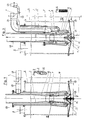
- a pipe element 1 is arranged, which is connected to a delivery line, not shown.
- a nozzle 2 is integrated in the tubular element 1 and is used for supplying the conveying means, the nozzle 2 being followed by a constriction 3.
- the nozzle 2 in the tubular element 1 is preceded by a gas-permeable sleeve 10, which serves for the dissolution of the frictional engagement (fluidization) of the conveyed material and for the production of a conveyed material / gas mixture, the latter being fed to the nozzle 2 by means of gravity or mechanical feed.
- This arrangement forms a transmitter.
- the nozzle 2 is designed as an annular nozzle, while in FIGS. 13 and 14 a central nozzle arrangement 2 is designed as a Laval nozzle.
- Lines 4 are provided for supplying the conveying means in the form of compressed gas.
- the transmitter 1 to 3 is inserted into a container 5, which is supplied with material to be conveyed via an opening 6 and has a ventilated bottom 7.
- a ventable traffic cone 8 is additionally arranged.
- the compressed gas is supplied via line 4 and is supplied to ring nozzle 2 via an annular space 9 surrounding tubular element 1.
- the pressurized gas supplies the inlet area 11 of the tubular element 1 with a permeable inner wall 10 made of porous material, so that the conveyed material located in the inlet area 11 can be fluidized.
- the conveyed material is transported by the material column serving as a closure and the propellant gas jet formed by the supplied compressed gas via the nozzle 2 brings the conveyed material to the required initial conveying speed and accelerates it with a diffuser formed by the constriction 3.
- the material to be conveyed is fluidized in the inlet region 11 by the compressed gas emerging via the permeable inner wall 10.
- the conveyed material pressure from the material column and the pressure difference, which results from the pulse size of the conveying means as it emerges from the nozzle 2 in the region of the constriction 3 as a Venturi tube, are also used for conveying.
- the ring nozzle 2 has a sealing ring 12 which can be raised by the compressed gas as a conveying means and which closes the passage when the pressure drops.
- This principle of the transmitting device is also implemented in all further exemplary embodiments and is only adapted to the needs that arise.
- FIG. 5 an embodiment of a transmitting device is shown in which the conveyed material is fed by gravity via a pipe 14 with a buffer zone 20, which has a non-return valve 15. All other elements are identical to the previously described exemplary embodiments.
- the bend of the pipe 14 provided with openings 14 ' is provided with a gas-permeable cover 14', which is designed for fluidization of the conveyed material in this area and corresponds functionally to the ventilated floor 7.
- a screw conveyor 16 is provided for supplying the material to be conveyed, which also brings about a necessary closure.
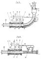
- FIG. 7 Another embodiment of a pressurized transmitter is shown in FIG. 7. It is used in a container 17, an aerated or slightly inclined ventilated base 18 being provided and a decreasing column of material being assumed. For a pressure-relieved material supply to the screw 19, a hood 18 'is provided. A screw conveyor 19 is therefore arranged, which brings the material to be conveyed into a buffer zone 20. In the inlet area 11 of the tubular element 1, expansion is brought about by supplying pressurized gas 10 via the permeable inner wall, and thus a material speed can be generated. This applies to everyone Embodiments with permeable inner wall 10, wherein the buffer zone 20 and, in the case of gravity feed, optionally together with a mechanical material feed, the closing function is formed. Otherwise, the transport takes place in the manner already described using the compressed gas supplied by means of the nozzle 2.
- the pipe element 1 is preceded by a suction nozzle 21. Otherwise, the transmitter is of the same design.
- a transmitter 1 to 3 is arranged in a pressure vessel 22, which can also be provided with an inclined bottom according to Fig. 1 and 3, but meets the pressure requirements. This arrangement is intended for a higher pressure build-up.
- a compressed gas is applied to the material level.
- the guide cone 8 is provided with an additional nozzle 23 and a compressed gas supply in order to achieve a pre-acceleration.
- the nozzle 23 is integrated in the traffic cone independently of the transmitter devices in accordance with the respective need.
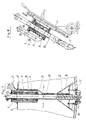
- a mobile arrangement is shown.
- the inlet area 11 is held by spacers 24 from the floor and additionally provided with nozzles 25.
- This training serves in particular to accommodate piles.
- the difference of Fig. 11 and Fig. 12 is that in Fig. 12 is again a closed space 13 with a line 4 'for pressurized gas supply is provided.
- a space 26 is provided with a line 4 ⁇ for supplying the nozzles 25 in order to fluidize the To achieve material to be conveyed in the peripheral inlet area of the tubular element.
- FIGS. 13 and 14 deviate from the previously discussed exemplary embodiments and are designed with a central nozzle 2 'in the form of a Laval nozzle.
- the compressed gas is supplied via lines 4, wherein in FIG. 14 a line 4 'is again led to the separated space 13 in order to supply the permeable area 10 in the input area 11 for fluidization.
- an additional feed screw with a downstream check valve can be provided for a higher pressure build-up in the system. This results in a step-like seal and reduces wear and tear.
- sludge sewage sludge
- sludge also in the form of contaminated, sandy, abrasive and / or aggressive sludges, which are due to their consistency with conventional feed pumps cannot be funded or can only be funded to a limited extent.
- a low-viscosity medium may be provided as a conveying means, which in conventional pump units is the one required for the conveyance Experiences pressure build-up. Conveyed goods with a high viscosity can be efficiently conveyed in this form with a medium of lower viscosity as a conveying medium in pipes.
Landscapes
- Engineering & Computer Science (AREA)
- Mechanical Engineering (AREA)
- Air Transport Of Granular Materials (AREA)
- Control Of Conveyors (AREA)
- Pipeline Systems (AREA)
- Jet Pumps And Other Pumps (AREA)
Claims (8)
- Dispositif de transport sous la forme d'une station d'envoi de matières pulvérulentes ou poudreuses à l'aide d'un gaz, et particulièrement de l'air, comme moyen de transport, dans des conduits dans lequel la station d'envoi est conçue comme un élément de tête de conduit (1) et dans lequel le gaz est appliqué à la matière à transporter au niveau de l'admission (11) de l'élément de conduit (1) par une tuyère (2) y accouplée et où l'obturation par la matière en mouvement est réalisable en amont de l'admission (11), l'élément de conduit (1) consistant en une tuyère combinée (2) d'alimentation en matière à transporter et en un étranglement (3) en aval de la tuyère,
caractérisé en ce qu'une section d'admission (11) de l'élément de conduit (1) en amont de la tuyère (2) est disposée pour soit être plongée dans la matière à transporter soit pour recevoir ladite matière et en ce que la fluidisation au niveau de l'admission (11) de l'élément de conduit est obtenue soit par une douille (10) perméable au gaz et/ou par un cône de guidage (8, 10) perméable au gaz. - Dispositif de transport selon la revendication 1, caractérisé en ce que la tuyère sous forme de tuyère annulaire (2) est munie d'un anneau d'obturation (12) maintenu levé par la matière à transporter et qui obture la tuyère annulaire (2) par gravité en cas de perte de pression.
- Dispositif de transport selon la revendication 1, caractérisé en ce qu'il est prévu une tuyère centrale (2') et la formation d'un anneau d'admission de matière à transporter, dans lequel la tuyère centrale (2') est composée d'une douille (10) perméable au gaz et d'un cône de guidage en aval.
- Dispositif de transport selon la revendication 1, caractérisé en ce que la tuyère (2) est de type Laval.
- Dispositif de transport selon les revendications 1 à 4, caractérisé en ce que l'admission de la matière de propulsion (4) dans la tuyère (2) pour la fluidisation de la matière à transporter est assurée par une alimentation commune, telle une cavité annulaire (9), de la section perméable d'admission (11) de l'élément de conduit (1).
- Dispositif de transport selon les revendications 1 à 5, caractérisé en ce que l'admission de la matière de propulsion (4) dans la tuyère (2) et dans la section perméable d'admission (11) séparée de l'élément de conduit (1) pour la fluidisation de la matière à transporter est acheminé par des admissions séparées (4,4') de matière de propulsion.
- Dispositif de transport selon les revendications 1 à 6, caractérisé en ce que l'on ajoute un cône de guidage (8) à la section d'admission (11) de l'élément de conduit (1).
- Dispositif de transport selon la revendication 7, caractérisé en ce que le cône (8) est raccordé à une alimentation en matière de propulsion et que ledit cône est muni d'injecteurs (23) ou d'une section perméable pour la fluidisation de la matière.
Applications Claiming Priority (2)
| Application Number | Priority Date | Filing Date | Title |
|---|---|---|---|
| DE3836380 | 1988-10-26 | ||
| DE3836380A DE3836380A1 (de) | 1988-10-26 | 1988-10-26 | Foerdervorrichtung in form eines sendegeraetes fuer staubfoermige oder feinkoernige gueter |
Publications (3)
| Publication Number | Publication Date |
|---|---|
| EP0366104A2 EP0366104A2 (fr) | 1990-05-02 |
| EP0366104A3 EP0366104A3 (fr) | 1991-01-30 |
| EP0366104B1 true EP0366104B1 (fr) | 1994-07-27 |
Family
ID=6365912
Family Applications (1)
| Application Number | Title | Priority Date | Filing Date |
|---|---|---|---|
| EP89119791A Expired - Lifetime EP0366104B1 (fr) | 1988-10-26 | 1989-10-25 | Dispositif de transport sous la forme d'une station d'envoi de matières pulvérulentes ou poudreuses |
Country Status (4)
| Country | Link |
|---|---|
| EP (1) | EP0366104B1 (fr) |
| AT (1) | ATE109109T1 (fr) |
| DE (2) | DE3836380A1 (fr) |
| ES (1) | ES2060719T3 (fr) |
Families Citing this family (3)
| Publication number | Priority date | Publication date | Assignee | Title |
|---|---|---|---|---|
| DE4432994C2 (de) * | 1994-09-16 | 2003-01-30 | Gerd Krischik | Anlage zur Ausschleusung von Feinstäuben |
| DE29723225U1 (de) | 1997-07-10 | 1998-06-04 | Kolb, Robert, jun., 88046 Friedrichshafen | Pneumatische Vorrichtung zum Ansaugen von Farbpulver aus einem Behältnis |
| CN102295167A (zh) * | 2011-05-26 | 2011-12-28 | 合肥水泥研究设计院 | 一种用于负压气力卸船装置上的流态化吸嘴装置 |
Family Cites Families (8)
| Publication number | Priority date | Publication date | Assignee | Title |
|---|---|---|---|---|
| DE133410C (fr) * | ||||
| DE1182594B (de) * | 1962-08-10 | 1964-11-26 | Josef Haarmann K G Appbau | Vorrichtung zum gleichmaessigen Austragen von staubfoermigen Guetern aus einem geschlossenen Behaelter in eine Foerderleitung ueber ein Gutaustragsrohr |
| FR92502E (fr) * | 1964-07-09 | 1968-11-22 | Transporteur pneumatique de matériaux en vrac par gaine de soufflage | |
| DE1431782A1 (de) * | 1965-09-06 | 1968-11-28 | Hermann Schmidt | Vorrichtung zum pneumatischen Foerdern von Schuettgut |
| DE1913026A1 (de) * | 1969-03-14 | 1970-09-17 | Zarges Leichtbau Gmbh | Verfahren und Vorrichtung zur Entleerung von Behaeltern fuer koerniges bzw. staubfoermiges rieselfaehiges Gut mittels Druckgas |
| GB1362509A (en) * | 1973-04-12 | 1974-08-07 | Hascon Uk Ltd | Apparatus for transporting flowable particulate material |
| SE399734B (sv) * | 1976-07-05 | 1978-02-27 | Stabilator Ab | Sett och anordning for rortransport av material |
| DE3439806A1 (de) * | 1984-10-31 | 1986-04-30 | Claudius Peters Ag, 2000 Hamburg | Pneumatischer schuettgutfoerderer |
-
1988
- 1988-10-26 DE DE3836380A patent/DE3836380A1/de not_active Withdrawn
-
1989
- 1989-10-25 EP EP89119791A patent/EP0366104B1/fr not_active Expired - Lifetime
- 1989-10-25 ES ES89119791T patent/ES2060719T3/es not_active Expired - Lifetime
- 1989-10-25 AT AT89119791T patent/ATE109109T1/de not_active IP Right Cessation
- 1989-10-25 DE DE58908101T patent/DE58908101D1/de not_active Expired - Fee Related
Also Published As
| Publication number | Publication date |
|---|---|
| EP0366104A2 (fr) | 1990-05-02 |
| DE3836380A1 (de) | 1990-05-03 |
| ES2060719T3 (es) | 1994-12-01 |
| DE58908101D1 (de) | 1994-09-01 |
| ATE109109T1 (de) | 1994-08-15 |
| EP0366104A3 (fr) | 1991-01-30 |
Similar Documents
| Publication | Publication Date | Title |
|---|---|---|
| EP1688718B1 (fr) | Procédé et dispositif pour le dosage et pour le transport pneumatique de matières en vrac s'écoulant difficilement | |
| EP0268126B1 (fr) | Procédé pour augmenter la quantité de poudre délivrée à un appareil de revêtement à poudre, et appareil de revêtement à poudre | |
| WO2003026991A1 (fr) | Dispositif et procede de transport pneumatique | |
| DE3420616C2 (fr) | ||
| WO2003024613A1 (fr) | Dispositif pour transporter de la poudre et procede de fonctionnement associe | |
| EP2129986B1 (fr) | Dispositif de dosage et/ou de transport de matières solides pulvérulentes et/ou aptes à l'écoulement | |
| EP3052367A1 (fr) | Dispositif de sablage pour véhicule ferroviaire et procédé de dosage de sable pour véhicule ferroviaire | |
| EP0366104B1 (fr) | Dispositif de transport sous la forme d'une station d'envoi de matières pulvérulentes ou poudreuses | |
| DE102005013091B3 (de) | Vorrichtung zum Fördern pulverförmiger fluidisierter Medien | |
| EP1320504B1 (fr) | Dispositif pour l'introduction de matieres en vrac a ecoulement difficile dans une conduite d'acheminement | |
| EP3568279A1 (fr) | Fabrication additive avec transport de matières transportées par surpression | |
| DE19720528A1 (de) | Vorrichtung und Verfahren zum Vermischen eines ersten Fluids mit einem zweiten Fluid | |
| WO2008006429A1 (fr) | Dispositif pour le transport de milieux fluidisés pulvérulents | |
| DE102009032908B4 (de) | Verfahren und Vorrichtung zum Fördern und Verteilen von Pulvern | |
| DE19752005A1 (de) | Vorrichtung und Verfahren zur Vermischung eines ersten Fluids mit einem zweiten Fluid | |
| DE19644727C2 (de) | Regeldüse zum Beschleunigen und Regeln von Fördergütern in pneumatischen Feststofförderanlagen | |
| DE3813551A1 (de) | Vorrichtung zur steilfoerderung von baustoff im untertagebetrieb | |
| WO2008006452A1 (fr) | Dispositif d'alimentation en matières pulvérulentes | |
| DE10334485B4 (de) | Sendebehälter für die pneumatische Förderung von pulverförmigem Gut | |
| WO2008006419A1 (fr) | Dispositif de conduite d'un milieu gazeux | |
| EP3254807B1 (fr) | Dispositif et procede de nettoyage avec un dispositif de projection de particules | |
| DE3407402A1 (de) | Pneumatisches foerderverfahren fuer fliessfaehige schuettgueter | |
| WO2008006421A1 (fr) | Dispositif d'alimentation en matières fluidifiables | |
| DE423136C (de) | Vorrichtung zum Foerdern von pulverfoermigem Brennstoff in Feuerungen durch ein gasfoermiges Druckmittel | |
| EP1429982A1 (fr) | Dispositif et procede de transport pneumatique |
Legal Events
| Date | Code | Title | Description |
|---|---|---|---|
| PUAI | Public reference made under article 153(3) epc to a published international application that has entered the european phase |
Free format text: ORIGINAL CODE: 0009012 |
|
| AK | Designated contracting states |
Kind code of ref document: A2 Designated state(s): AT CH DE ES FR GB IT LI SE |
|
| PUAL | Search report despatched |
Free format text: ORIGINAL CODE: 0009013 |
|
| AK | Designated contracting states |
Kind code of ref document: A3 Designated state(s): AT CH DE ES FR GB IT LI SE |
|
| 17P | Request for examination filed |
Effective date: 19910118 |
|
| 17Q | First examination report despatched |
Effective date: 19930223 |
|
| GRAA | (expected) grant |
Free format text: ORIGINAL CODE: 0009210 |
|
| AK | Designated contracting states |
Kind code of ref document: B1 Designated state(s): AT CH DE ES FR GB IT LI SE |
|
| PG25 | Lapsed in a contracting state [announced via postgrant information from national office to epo] |
Ref country code: IT Free format text: LAPSE BECAUSE OF FAILURE TO SUBMIT A TRANSLATION OF THE DESCRIPTION OR TO PAY THE FEE WITHIN THE PRE;WARNING: LAPSES OF ITALIAN PATENTS WITH EFFECTIVE DATE BEFORE 2007 MAY HAVE OCCURRED AT ANY TIME BEFORE 2007. THE CORRECT EFFECTIVE DATE MAY BE DIFFERENT FROM THE ONE RECORDED.SCRIBED TIME-LIMIT Effective date: 19940727 |
|
| REF | Corresponds to: |
Ref document number: 109109 Country of ref document: AT Date of ref document: 19940815 Kind code of ref document: T |
|
| REF | Corresponds to: |
Ref document number: 58908101 Country of ref document: DE Date of ref document: 19940901 |
|
| PG25 | Lapsed in a contracting state [announced via postgrant information from national office to epo] |
Ref country code: SE Effective date: 19941027 |
|
| REG | Reference to a national code |
Ref country code: ES Ref legal event code: FG2A Ref document number: 2060719 Country of ref document: ES Kind code of ref document: T3 |
|
| ET | Fr: translation filed | ||
| GBT | Gb: translation of ep patent filed (gb section 77(6)(a)/1977) |
Effective date: 19941103 |
|
| PLBE | No opposition filed within time limit |
Free format text: ORIGINAL CODE: 0009261 |
|
| STAA | Information on the status of an ep patent application or granted ep patent |
Free format text: STATUS: NO OPPOSITION FILED WITHIN TIME LIMIT |
|
| 26N | No opposition filed | ||
| PGFP | Annual fee paid to national office [announced via postgrant information from national office to epo] |
Ref country code: GB Payment date: 19971016 Year of fee payment: 9 |
|
| PGFP | Annual fee paid to national office [announced via postgrant information from national office to epo] |
Ref country code: FR Payment date: 19971021 Year of fee payment: 9 |
|
| PG25 | Lapsed in a contracting state [announced via postgrant information from national office to epo] |
Ref country code: GB Free format text: LAPSE BECAUSE OF NON-PAYMENT OF DUE FEES Effective date: 19981025 |
|
| GBPC | Gb: european patent ceased through non-payment of renewal fee |
Effective date: 19981025 |
|
| PG25 | Lapsed in a contracting state [announced via postgrant information from national office to epo] |
Ref country code: FR Free format text: LAPSE BECAUSE OF NON-PAYMENT OF DUE FEES Effective date: 19990630 |
|
| REG | Reference to a national code |
Ref country code: FR Ref legal event code: ST |
|
| PGFP | Annual fee paid to national office [announced via postgrant information from national office to epo] |
Ref country code: ES Payment date: 20020912 Year of fee payment: 14 |
|
| PG25 | Lapsed in a contracting state [announced via postgrant information from national office to epo] |
Ref country code: ES Free format text: LAPSE BECAUSE OF NON-PAYMENT OF DUE FEES Effective date: 20031027 |
|
| REG | Reference to a national code |
Ref country code: ES Ref legal event code: FD2A Effective date: 20031027 |
|
| PGFP | Annual fee paid to national office [announced via postgrant information from national office to epo] |
Ref country code: CH Payment date: 20051228 Year of fee payment: 17 |
|
| PGFP | Annual fee paid to national office [announced via postgrant information from national office to epo] |
Ref country code: AT Payment date: 20061027 Year of fee payment: 18 |
|
| PG25 | Lapsed in a contracting state [announced via postgrant information from national office to epo] |
Ref country code: CH Free format text: LAPSE BECAUSE OF NON-PAYMENT OF DUE FEES Effective date: 20061031 Ref country code: LI Free format text: LAPSE BECAUSE OF NON-PAYMENT OF DUE FEES Effective date: 20061031 |
|
| REG | Reference to a national code |
Ref country code: CH Ref legal event code: PL |
|
| PGFP | Annual fee paid to national office [announced via postgrant information from national office to epo] |
Ref country code: DE Payment date: 20071011 Year of fee payment: 19 |
|
| PG25 | Lapsed in a contracting state [announced via postgrant information from national office to epo] |
Ref country code: AT Free format text: LAPSE BECAUSE OF NON-PAYMENT OF DUE FEES Effective date: 20071025 |
|
| PG25 | Lapsed in a contracting state [announced via postgrant information from national office to epo] |
Ref country code: DE Free format text: LAPSE BECAUSE OF NON-PAYMENT OF DUE FEES Effective date: 20090501 |