EP1688718B1 - Procédé et dispositif pour le dosage et pour le transport pneumatique de matières en vrac s'écoulant difficilement - Google Patents
Procédé et dispositif pour le dosage et pour le transport pneumatique de matières en vrac s'écoulant difficilement Download PDFInfo
- Publication number
- EP1688718B1 EP1688718B1 EP06000677A EP06000677A EP1688718B1 EP 1688718 B1 EP1688718 B1 EP 1688718B1 EP 06000677 A EP06000677 A EP 06000677A EP 06000677 A EP06000677 A EP 06000677A EP 1688718 B1 EP1688718 B1 EP 1688718B1
- Authority
- EP
- European Patent Office
- Prior art keywords
- longitudinal conveyor
- bulk material
- conveyor
- metering
- compressed gas
- Prior art date
- Legal status (The legal status is an assumption and is not a legal conclusion. Google has not performed a legal analysis and makes no representation as to the accuracy of the status listed.)
- Active
Links
- 239000013590 bulk material Substances 0.000 title claims abstract description 70
- 238000000034 method Methods 0.000 title claims abstract description 29
- 230000002572 peristaltic effect Effects 0.000 claims description 3
- 238000005303 weighing Methods 0.000 claims description 3
- 239000000463 material Substances 0.000 abstract description 3
- 239000007789 gas Substances 0.000 description 39
- 239000003570 air Substances 0.000 description 7
- 239000000203 mixture Substances 0.000 description 7
- 239000002245 particle Substances 0.000 description 7
- UQSXHKLRYXJYBZ-UHFFFAOYSA-N Iron oxide Chemical compound [Fe]=O UQSXHKLRYXJYBZ-UHFFFAOYSA-N 0.000 description 6
- 238000013459 approach Methods 0.000 description 3
- 238000007906 compression Methods 0.000 description 3
- 238000009826 distribution Methods 0.000 description 3
- IJGRMHOSHXDMSA-UHFFFAOYSA-N Atomic nitrogen Chemical compound N#N IJGRMHOSHXDMSA-UHFFFAOYSA-N 0.000 description 2
- 230000006835 compression Effects 0.000 description 2
- 230000000694 effects Effects 0.000 description 2
- 238000004519 manufacturing process Methods 0.000 description 2
- 238000012545 processing Methods 0.000 description 2
- 238000009423 ventilation Methods 0.000 description 2
- 238000013022 venting Methods 0.000 description 2
- 238000005273 aeration Methods 0.000 description 1
- 239000007900 aqueous suspension Substances 0.000 description 1
- QVGXLLKOCUKJST-UHFFFAOYSA-N atomic oxygen Chemical compound [O] QVGXLLKOCUKJST-UHFFFAOYSA-N 0.000 description 1
- 230000015572 biosynthetic process Effects 0.000 description 1
- 239000000969 carrier Substances 0.000 description 1
- 230000001413 cellular effect Effects 0.000 description 1
- 238000010276 construction Methods 0.000 description 1
- 238000007599 discharging Methods 0.000 description 1
- 238000005516 engineering process Methods 0.000 description 1
- 230000005284 excitation Effects 0.000 description 1
- 238000005243 fluidization Methods 0.000 description 1
- 230000005484 gravity Effects 0.000 description 1
- 239000003673 groundwater Substances 0.000 description 1
- 229910052500 inorganic mineral Inorganic materials 0.000 description 1
- 238000012432 intermediate storage Methods 0.000 description 1
- 238000005259 measurement Methods 0.000 description 1
- 239000011707 mineral Substances 0.000 description 1
- 229910052757 nitrogen Inorganic materials 0.000 description 1
- 229910052756 noble gas Inorganic materials 0.000 description 1
- 150000002835 noble gases Chemical class 0.000 description 1
- 210000000056 organ Anatomy 0.000 description 1
- 239000001301 oxygen Substances 0.000 description 1
- 229910052760 oxygen Inorganic materials 0.000 description 1
- 239000000049 pigment Substances 0.000 description 1
- 230000001737 promoting effect Effects 0.000 description 1
- 238000005096 rolling process Methods 0.000 description 1
- 238000007789 sealing Methods 0.000 description 1
- 229910000162 sodium phosphate Inorganic materials 0.000 description 1
- 239000001488 sodium phosphate Substances 0.000 description 1
- 239000007787 solid Substances 0.000 description 1
- 239000000725 suspension Substances 0.000 description 1
- 230000029305 taxis Effects 0.000 description 1
- RYFMWSXOAZQYPI-UHFFFAOYSA-K trisodium phosphate Chemical compound [Na+].[Na+].[Na+].[O-]P([O-])([O-])=O RYFMWSXOAZQYPI-UHFFFAOYSA-K 0.000 description 1
- 238000001132 ultrasonic dispersion Methods 0.000 description 1
- 238000011144 upstream manufacturing Methods 0.000 description 1
Images
Classifications
-
- B—PERFORMING OPERATIONS; TRANSPORTING
- B65—CONVEYING; PACKING; STORING; HANDLING THIN OR FILAMENTARY MATERIAL
- B65G—TRANSPORT OR STORAGE DEVICES, e.g. CONVEYORS FOR LOADING OR TIPPING, SHOP CONVEYOR SYSTEMS OR PNEUMATIC TUBE CONVEYORS
- B65G53/00—Conveying materials in bulk through troughs, pipes or tubes by floating the materials or by flow of gas, liquid or foam
- B65G53/04—Conveying materials in bulk pneumatically through pipes or tubes; Air slides
- B65G53/06—Gas pressure systems operating without fluidisation of the materials
- B65G53/08—Gas pressure systems operating without fluidisation of the materials with mechanical injection of the materials, e.g. by screw
-
- B—PERFORMING OPERATIONS; TRANSPORTING
- B65—CONVEYING; PACKING; STORING; HANDLING THIN OR FILAMENTARY MATERIAL
- B65G—TRANSPORT OR STORAGE DEVICES, e.g. CONVEYORS FOR LOADING OR TIPPING, SHOP CONVEYOR SYSTEMS OR PNEUMATIC TUBE CONVEYORS
- B65G53/00—Conveying materials in bulk through troughs, pipes or tubes by floating the materials or by flow of gas, liquid or foam
- B65G53/04—Conveying materials in bulk pneumatically through pipes or tubes; Air slides
- B65G53/06—Gas pressure systems operating without fluidisation of the materials
- B65G53/10—Gas pressure systems operating without fluidisation of the materials with pneumatic injection of the materials by the propelling gas
- B65G53/12—Gas pressure systems operating without fluidisation of the materials with pneumatic injection of the materials by the propelling gas the gas flow acting directly on the materials in a reservoir
-
- G—PHYSICS
- G01—MEASURING; TESTING
- G01G—WEIGHING
- G01G13/00—Weighing apparatus with automatic feed or discharge for weighing-out batches of material
- G01G13/02—Means for automatically loading weigh pans or other receptacles, e.g. disposable containers, under control of the weighing mechanism
- G01G13/022—Material feeding devices
- G01G13/026—Material feeding devices by mechanical conveying means, e.g. belt or vibratory conveyor
-
- B—PERFORMING OPERATIONS; TRANSPORTING
- B65—CONVEYING; PACKING; STORING; HANDLING THIN OR FILAMENTARY MATERIAL
- B65G—TRANSPORT OR STORAGE DEVICES, e.g. CONVEYORS FOR LOADING OR TIPPING, SHOP CONVEYOR SYSTEMS OR PNEUMATIC TUBE CONVEYORS
- B65G53/00—Conveying materials in bulk through troughs, pipes or tubes by floating the materials or by flow of gas, liquid or foam
- B65G53/34—Details
- B65G53/40—Feeding or discharging devices
- B65G53/48—Screws or like rotary conveyors
Definitions
- the invention relates to a method and a device for the pneumatic conveying of heavy-flowing bulk material.
- EP 0 692 411 A1 An aforementioned method and an associated device are made EP 0 692 411 A1 known.
- This known technique uses a method for the pneumatic conveying of bulk material, which is transported in a pipeline from a job site by means of a gas flow to a receiving location, wherein the bulk material in the dense stream at a defined speed by generating a plug in the pipeline this partially filled and after closing the Inlet opening of the pipeline by means of an inlet closure valve, this completely or partially emptied by overpressure and wherein a continuous repeating this process, a quasi-continuous mass flow can be produced from the job site to the receiving site.
- the disadvantage here is that in blunt, difficult-flowing goods, the vacuum is not sufficient to fill the suction lines. As a result, the closure organs and the delivery process are disturbed.
- the screw pumps used for decades have been provided with a high KW drive power in order to convey the bulk material plug in front of the closing flap between the worm shaft and the delivery line, which is blocked by the delivery pressure.
- Auger pumps are mainly used for minerals.
- the DD 267850 A1 shows that screw conveyors without flap can also be used to feed in bulk material if an infeed container is installed above the screw inlet.
- the screw does not serve to overcome Einschleus horrdifferenz that would be subject to leaks, but has the task of loading ⁇ , that is, to regulate the ratio of bulk material to conveying air or to keep constant.
- US 2,831,587 A discloses a screw pump for continuously conveying heavy flowing bulk material to a zone at a higher pressure than that below which the bulk material is located prior to production (multi-stage compression process).
- multi-stage compression process at least two screw pumps with an intermediate intermediate container gas-tight connected in series, with a compression of the bulk material within the individual screw pump is achieved by tapering the screw housing and the screw.
- the gas pressure in this multi-stage compression method is increased before each screw pump.
- the invention is therefore based on the object to provide a method and an apparatus for metering a predetermined amount of poorly flowing bulk material, to empty completely and to promote a target.
- the distribution of heavy flowing bulk material in the longitudinal conveyor (1) is preferably uniform.
- the pressurized gas (17) is added at a pressure that allows pneumatic delivery. This pressure is generally> 1 bar, but may vary from system to system.
- the compressed gas (17) may preferably consist of compressed air, nitrogen, oxygen, other noble gases or mixtures thereof.
- Bulky bulk material in the sense of the application describes bulk material that forms bridges or bulk material that does not leak without excitation or mechanical support.
- Examples of poorly flowing bulk material are pigments and solids which have a characteristic value D (v, 0.9) of not more than 40 ⁇ m.
- the D (v, 0.9) characteristic is known to the person skilled in the art and is generally described in US Pat Volume particle size distributions the particle diameter, where 90% of the particles of a volume particle size distribution have a particle diameter smaller than D (v, 0.9), and 10% of the particles have a larger particle diameter than D (v, 0.9).
- “Completely emptied” in the sense of the application means that ⁇ 97% of the heavy-flow bulk material dosed in the longitudinal conveyor (1) is emptied by the process. Preferably, the longitudinal conveyor (1) ⁇ 98% is emptied.
- “Wandbarer” in the sense of the application means that the mechanical conveyor (9) is designed with close clearance to the wall, and as close as allow the manufacturing tolerances of screw and housing.
- the mechanical longitudinal conveyor (1) causes both the feeding of the poorly flowing bulk material in the feed line (19) and the complete discharge after pressurization. It is essential that the mechanical conveyor (9) is designed so that it supports the pneumatic conveying, so that the heavy-flowing bulk material can not settle on the ground and the longitudinal conveyor (1) is completely emptied.
- the control device (36) used in the method serves to control the metering of the bulk material and the complete emptying of the longitudinal conveyor (1).
- control device (36) controls and controls the course of the metering via the metering device (8) in the longitudinal conveyor (1), the circuit of the shut-off valves (4), (31), (32) and the compressed gas valves (30) and the on - And off the worm gear motor (7).
- the metering and emptying of the longitudinal conveyor (1) is preferably repeated a plurality of times, during the metering of the longitudinal conveyor (1) pressurized gas (17) through an additional bypass line (12) in the delivery line (19) is passed to a flow in the delivery line ( 19) of 15 to 50 m / s.
- the bulk material is preferably moved through the conveying line (19) such that the metered quantity of bulk material reaches the receiving location completely without settling.
- Settling in the sense of the application means that the bulk material settles at the bottom of the longitudinal conveyor (1) or at the bottom of the delivery line (19) and is no longer conveyed by the gas flow, which is fed by the compressed gas (17).
- the invention also relates to a device for the pneumatic conveying of heavy-flowing bulk material, comprising an allocating device (8), a longitudinal conveyor (1) with a mechanical conveyor (9) which is mounted substantially everywhere in the longitudinal conveyor (1), a geared motor (7 ) for the mechanical conveyor (9), Druckgaseinlass- (11) and outlet ducts (10) respectively at the other end of the longitudinal conveyor (1), a feed line (19) for the bulk material or compressed gas (17) and a control device (36) characterized in that the metering of a predetermined amount of poorly flowing bulk material in the longitudinal conveyor (1) and the complete emptying of the longitudinal conveyor (1) by the control device (36) can be controlled.
- a device which has one or more passages (13) for compressed gas (17) is preferred.
- the mechanical conveyors (9) used are preferably a ribbon screw, paddle screw, full-blade screw or a twin screw, in particular a double paddle screw or twin-screw screw.
- a corkscrew-like flow is generated which, in conjunction with the mechanical conveying action of the screw, causes a complete emptying of the long conveyor (1).
- the addition of compressed gas (17) takes place at the compressed gas inlet line (11) and optionally at the passage (13) over the entire length of the long conveyor (1) and at the Druckgasauslasstechnisch (10) according to the state of the art available feeders.
- a corresponding device with a ribbon screw showed that heavy flowing bulk material with a high internal friction metering exactly introduced into the delivery line (19) and could be expelled with the support of the mechanical conveying effect.
- the passage (13) for the compressed gas (17) is preferably attached to the underside of the longitudinal conveyor (1). Bottom means doing on the lower semicircle of the longitudinal conveyor (1).
- a bypass line (12) with an annular gap or a T-piece behind the Druckgasauslass glaci (10) is mounted on the conveyor line (19).
- a pinch valve or a ball valve is preferably attached to the delivery line (19).
- an allocation device (8) is preferably used a vibrating floor, a screw conveyor, a position-controlled slide or a rotary valve.
- a peristaltic rolling device (18) is preferably arranged above the dispensing device (8).
- the discharge from feed containers (2) is promoted as big bags.
- a fluidizing device with air nozzles or a vibrating bottom is preferably used for the discharge from feed containers (2) such as silos and containers. Due to the fluidizing effect and the simultaneous taking place of the screw, it is possible to bring the bulk material trouble-free without the formation of a blockage and completely in the remaining portion of the delivery line (19).
- the dosage in the longitudinal conveyor (1) is preferably registered by one or more weighing devices (38). It is possible to monitor via a control device (36) that exactly the desired and requested amount of bulk material in the longitudinal conveyor (1) is introduced. Alternatively, the weight can also be determined by measuring the difference at an upstream feed container (2).
- a special embodiment of the device according to the invention now provides that a plurality of feed containers (2) open into the longitudinal conveyor (1) at a mutual distance. Such an embodiment is particularly advantageous when several components are to be dosed pneumatically over a longer distance according to a recipe, a mixture or a batch.
- a plurality of metering devices (8) are arranged, which are integrated in the control device (36) to control the dosage of the heavy-flowing bulk material.
- the devices described are constructed and connected in parallel.
- one or more devices are dosed by one or more dispensing devices (8).
- An advantage of the method according to the invention and the associated device is that now any partial bulk quantities can be formed with the new longitudinal conveyor (1) according to the invention. Due to the necessary bearings of a screw conveyor as a mechanical conveyor (9), it is accordingly provided that for longitudinal bulk material such longitudinal conveyor (1) are used with intermediate storage or even longitudinal conveyor (1) are arranged one behind the other, so as to promote a larger amount of bulk material ,
- the invention is therefore effected not only by the arrangement of a longitudinal conveyor (1) in a section of the conveying line (19), but also by a compressed gas inlet line (11) and optionally on the circumference of the housing of the longitudinal conveyor (1) arranged passages (13). for the compressed gas (17), which cause aeration of the heavy-flowing bulk material in the longitudinal conveyor (1) to make the heavy-flowing bulk material conveyed.
- the device according to the invention is placed in a silo battery in a channel of less than 50 cm depth or on the ground floor level, one saves a whole floor height, be it floor or basement, in particular the frequent practical problems with the groundwater level in bulk container unloading systems. Also, the connection to the gravity bulk carriers of the train under the tracks with reasonable unloading power can now be better realized than before.
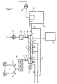
- FIG. 1 In general, a device according to the invention is shown, in which the heavy-flowing bulk material to be transported is stored in a big bag as a feed container (2).
- a predefined amount should be conveyed by means of the pneumatic conveyor into a target container (20) with receiving filter (35) and exhaust fan (40).
- the big bag as a feed container (2) can be automatically emptied by means known in the market Walk Hughesen.
- the poorly flowing bulk material is accordingly entered via the open butterfly valve (4) and an associated connection piece (5) in the arrow direction (6) in the longitudinal conveyor (1), wherein the longitudinal conveyor (1) the heavy-flowing bulk material over the length of the conveyor housing of the longitudinal conveyor (1 ).
- the displaced by the heavy flowing bulk material compressed gas (17) is passed through a vent filter (33).
- the filling of the longitudinal conveyor (1) can be controlled in the simplest way over a period of time (volumetric dosing). For accurate dosing purposes, the dosage of the longitudinal conveyor (1) is weight controlled. Various variants are possible for this purpose.
- the weight of the big bag as a feed container (2) is measured on the suspension. After discharging a certain amount of bulk material of the feed process in the longitudinal conveyor (1) is stopped. In another version, the weight of the longitudinal conveyor (1) is determined, which is equipped for this purpose with compensators. According to the increase in weight on the longitudinal conveyor (1), the dosage of the longitudinal conveyor (1) is turned off.
- the big bag as a feed container (2) can be emptied periodically in sections into a metering device as an allocation device (8).
- a metering device as an allocation device (8) the required amount of bulk material in the longitudinal conveyor (1) is introduced.
- the butterfly valve (4) and the ventilation flap (31) are closed.
- the compressed gas inlet line (11) the closed longitudinal conveyor (1) compressed gas (17) is supplied.
- the outlet closure member (32) is opened to the delivery line (19).
- the longitudinal conveyor (1) again turned on and the amounts of compressed gas are increased to a predetermined value.
- the fluidization device as a passage (13), the internal friction of the heavy-flowing bulk material is reduced and supports the promotion.
- the poorly flowing bulk material is conveyed out via the compressed gas (17) fed to the compressed gas inlet line (11) of the longitudinal conveyor (1) with the assistance of the longitudinal conveyor (1) and under the action, that is to say rotation of the mechanical conveyor (9).
- the longitudinal conveyor (1) causes a complete emptying of the poorly flowing bulk material. After emptying the Auslassver gleichorgan (32) and the compressed gas valves (30) of the compressed gas inlet line (11) are closed again.
- a bypass line (12) compressed gas (17) In order for the, in the conveying line (19) introduced, heavy flowing bulk material is conveyed to the destination, then via a bypass line (12) compressed gas (17) must be abandoned as a subsidy.
- the longitudinal conveyor (1) is expanded via the vent line and via the vent pipe (21) and via the vent filter (33). This is supported by the bleeder fan (34). Subsequently, a new promotion cycle can be initiated according to the above description.
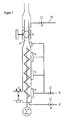
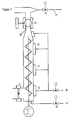
- the compressed gas (17) for the pneumatic conveying there is the possibility of feeding in through an annular gap in addition to the described possibility of feeding on the feed side FIG. 2 or a tee after FIG. 3 on the outlet side.
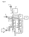
- FIG. 4 shows that the one longitudinal conveyor (1) for the pneumatic conveying is metered, while the other longitudinal conveyor (1a) empties the introduced heavy-flowing bulk material and vice versa.
- a pneumatic delivery from a silo was selected as a feed container (2) and a cellular wheel as a metering device (8) out.
- the double system described above with alternating operation is preferably operated via a controller (36).
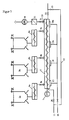
- FIG. 5 shows an industrial system for metering components via the pneumatic pressure conveying device according to the invention. From this embodiment, significant advantages of the invention will become apparent. It is shown that for the promotion of various heavy-flowing bulk materials alone a device is necessary, which is metered via a plurality of feed containers (2a-c) and allocation devices (8a-c).
- the longitudinal conveyor (1) can also consist of a plurality of serially connected one behind the other and connected in the transport direction individual longitudinal conveyors (1), so that also on the bottom side of the thus formed, relatively long tube vessel of the longitudinal conveyor (1) has a plurality of passages (13) Compressed gas (17) are arranged.
- the mechanical conveyor (9) can now be programmatically filled from different feed containers (2) (for example, big bags).
- the butterfly valves (4a-c) are opened, and the metering devices (8a-c), in Fig. 5 Metering screws as allocation device (8), turned on.
- the butterfly valves (4a-c) and the venting flap (31) are closed. The intended for a mixture or approach amount of poorly flowing bulk material can then be promoted in the manner described above to a processing plant.
- a particular advantage of the method described is that the mixture or the batch can be presented in the longitudinal conveyor (1), so that the period of time for promoting the mixture of poorly flowing bulk material or the approach is very short. As a result of this procedure, the devices according to the invention increase the downstream equipment in terms of their productivity.
- control means (36) are used those in which the coordinated parameters of the speed of the screw of the mechanical conveyor (9) and the amount of compressed gas (17) are stored.
- the speed of the screw of the mechanical conveyor (9) and the amount of compressed gas (17), can be controlled in an advantageous embodiment, depending on the pressure in the longitudinal conveyor (1) to prevent blockages in the pipeline.
- a device designed according to the application consisted of a screw tube as a longitudinal conveyor (1) with a diameter of 200 mm and a screw conveyor with a length of 2.5 m as a mechanical conveyor (9) which was mounted in the longitudinal conveyor (1).
- the heavy-flowing bulk material to be transported was an iron oxide with a D (v, 0.9) characteristic of 4.56 ⁇ m and a density of 0.45 t / m 3 .
- the D (v, 0.9) characteristic was determined by laser diffraction (Malvern Instruments "Mastersizer-S” instrument) in an aqueous suspension containing 0.1% sodium phosphate as a dispersing aid after a 200-W ultrasonic dispersion for two minutes.
- the heavy-flowing bulk material to be conveyed ran to the longitudinal conveyor (1) consisting of a screw conveyor from a feed container (2) via a shut-off valve (4) as allocation device (8). Behind the longitudinal conveyor (1) was a delivery line (19) with a nominal diameter of 65 mm and a length of 45 m downstream. At the discharge side of the longitudinal conveyor (1), the air displaced by the bulk material could be withdrawn as compressed gas (17) via a venting filter (33).
- the screw conveyor ran as a mechanical conveyor (9) with 60 U / min for 12 s, driven by a geared motor (7) from Bauer.
- the longitudinal conveyor (1) was metered with 30 kg of iron oxide.
- the butterfly valve (4) and the vent flap (31) was closed.
- Compressed air (17) was compressed air, which was then applied at a rate of 260 Nm 3 / h via the compressed gas inlet line (11) - which was in the end of the longitudinal conveyor (1) - and the passages (13) was abandoned.
- the longitudinal conveyor (1) was then with simultaneous flow with the compressed air and the action of the tape screw as a mechanical conveyor (9) in 20 s through the Duckgasauslass Arthur (10) - which was attached to the other end of the longitudinal conveyor (1) - emptied, the product has been completely transported via the delivery line (19) in the target container (20) with receiving filter (35) and suction fan (40). Of 30 kg dosed iron oxide 29.43 kg were thereby promoted, so that the longitudinal conveyor (1) was emptied to 98%. The pressure in the screw was 2.3 bar.
- the delivery cycle could be repeated several times in the same way.
Landscapes
- Engineering & Computer Science (AREA)
- Mechanical Engineering (AREA)
- Physics & Mathematics (AREA)
- General Physics & Mathematics (AREA)
- Air Transport Of Granular Materials (AREA)
- Filling Or Emptying Of Bunkers, Hoppers, And Tanks (AREA)
- Screw Conveyors (AREA)
- Loading Or Unloading Of Vehicles (AREA)
- Organic Low-Molecular-Weight Compounds And Preparation Thereof (AREA)
Claims (15)
- Dispositif de transport pneumatique d'une quantité prédéterminée de produit en vrac s'écoulant difficilement, comprenant
un dispositif d'amenée (8),
un transporteur longitudinal (1) doté d'un transporteur mécanique (9) installé dans le transporteur longitudinal (1) essentiellement en contact partout avec les parois,
un groupe motoréducteur (7) pour le transporteur mécanique (9),
un conduit (11) d'entrée de gaz sous pression et un conduit (10) de sortie de gaz sous pression disposés aux extrémités respectives du transporteur longitudinal (1),
un conduit de transport (19) pour le produit en vrac et le gaz sous pression (17) et un dispositif de commande (36),
caractérisé en ce que
le dosage d'une quantité prédéterminée de produit en vrac s'écoulant difficilement dans le transporteur longitudinal (1) et la vidange complète du transporteur longitudinal (1) peuvent être commandés par le dispositif de commande (36). - Dispositif selon la revendication 1, caractérisé en ce que le dispositif présente un ou plusieurs passages (13) pour le gaz sous pression (17).
- Dispositif selon l'une ou plusieurs des revendications 1 et 2, caractérisé en ce que le transporteur mécanique (9) est une vis à bande, une vis à aubes, une vis à volute continue ou une vis double et de préférence une vis à doubles aubes ou une vis à double bande.
- Dispositif selon l'une ou plusieurs des revendications 1 à 3, caractérisé en ce qu'un passage (13) pour le gaz sous pression (17) est disposé sur le côté inférieur du transporteur longitudinal (1).
- Dispositif selon l'une ou plusieurs des revendications 1 à 4, caractérisé en ce qu'un conduit de dérivation (12) de préférence doté d'un interstice annulaire ou d'une pièce en T est placé sur le dispositif de transport (19) en aval de la sortie (10).
- Dispositif selon l'une ou plusieurs des revendications 1 à 5, caractérisé en ce qu'une soupape écrasable ou une vanne à bille sont installées en aval du conduit (10) de sortie du gaz en direction du conduit de transport (19).
- Dispositif selon l'une ou plusieurs des revendications 1 à 6, caractérisé en ce que comme dispositif d'amenée (8), il utilise un fond vibrant, une vis de transport, un coulisseau à position contrôlée ou un sas à roue cellulaire.
- Dispositif selon l'une ou plusieurs des revendications 1 à 7, caractérisé en ce qu'un dispositif péristaltique à galet est disposé au-dessus du dispositif d'amenée (8).
- Dispositif selon l'une ou plusieurs des revendications 1 à 8, caractérisé en ce qu'un récipient d'amenée (2) doté d'un dispositif de fluidisation à tuyères d'air est disposé au-dessus du dispositif d'amenée (8).
- Dispositif selon l'une ou plusieurs des revendications 1 à 9, caractérisé en ce que le dosage du transporteur longitudinal (1) est enregistré par un ou plusieurs dispositifs de pesée (38).
- Dispositif selon l'une ou plusieurs des revendications là 10, caractérisé en ce que plusieurs dispositifs sont raccordés à parallèle.
- Dispositif selon l'une ou plusieurs des revendications 1 à 11, caractérisé en ce qu'un ou plusieurs dispositifs sont dosés par un ou plusieurs dispositifs d'amenée (8).
- Procédé de transport pneumatique d'une quantité prédéterminée de produit en vrac s'écoulant difficilement par recours au dispositif selon l'une ou plusieurs des revendications 1 à 12, et dans lequel- le produit en vrac est dosé dans un transporteur longitudinal (1) à l'aide d'un dispositif d'amenée (8),- le produit en vrac est ensuite vidé par un conduit de transport (19),le dosage dans le transporteur longitudinal (1) étant assuré au moyen du dispositif (8) qui amène le produit en vrac dans le transporteur longitudinal (1) et la vidange du transporteur longitudinal (1) est réalisée par action simultanée d'un transporteur mécanique (9) installé dans le transporteur longitudinal (1) essentiellement partout en contact avec les parois et d'un gaz sous pression (17) amené dans le caisson du transporteur longitudinal (1) de telle sorte que le transporteur longitudinal (1) soit vidé complètement lors de l'opération de vidange, le dispositif de commande (36) étant utilisé pour commander le dosage du produit en vrac et la vidange du transporteur longitudinal (1).
- Procédé selon la revendication 13, caractérisé en ce que le dosage et la vidange du transporteur longitudinal (1) sont répétés plusieurs fois, un gaz sous pression (17) étant amené dans le conduit de transport (19) par un conduit supplémentaire de dérivation (12) de manière à maintenir dans le conduit de transport (19) un écoulement de 15 à 50 m/s pendant le dosage du transporteur longitudinal (1).
- Procédé selon l'une ou plusieurs des revendications 13 et 14, caractérisé en ce que le produit en vrac est déplacé dans le conduit de transport (19) de telle sorte que la totalité de la quantité de produit en vrac dosée aboutisse à l'emplacement de réception sans se déposer.
Applications Claiming Priority (1)
| Application Number | Priority Date | Filing Date | Title |
|---|---|---|---|
| DE102005003620A DE102005003620A1 (de) | 2005-01-26 | 2005-01-26 | Verfahren und Vorrichtung zur pneumatischen Förderung von schwerfließendem Schüttgut |
Publications (2)
| Publication Number | Publication Date |
|---|---|
| EP1688718A1 EP1688718A1 (fr) | 2006-08-09 |
| EP1688718B1 true EP1688718B1 (fr) | 2010-08-04 |
Family
ID=36130037
Family Applications (1)
| Application Number | Title | Priority Date | Filing Date |
|---|---|---|---|
| EP06000677A Active EP1688718B1 (fr) | 2005-01-26 | 2006-01-13 | Procédé et dispositif pour le dosage et pour le transport pneumatique de matières en vrac s'écoulant difficilement |
Country Status (9)
| Country | Link |
|---|---|
| US (2) | US7413388B2 (fr) |
| EP (1) | EP1688718B1 (fr) |
| JP (1) | JP5370951B2 (fr) |
| CN (1) | CN1810612B (fr) |
| AT (1) | ATE476642T1 (fr) |
| CA (1) | CA2533719A1 (fr) |
| DE (2) | DE102005003620A1 (fr) |
| DK (1) | DK1688718T3 (fr) |
| ES (1) | ES2347809T3 (fr) |
Families Citing this family (37)
| Publication number | Priority date | Publication date | Assignee | Title |
|---|---|---|---|---|
| DE102005003620A1 (de) * | 2005-01-26 | 2006-08-03 | Lanxess Deutschland Gmbh | Verfahren und Vorrichtung zur pneumatischen Förderung von schwerfließendem Schüttgut |
| US7654778B2 (en) * | 2006-01-18 | 2010-02-02 | D & W Diesel, Inc. | Vacuum system for pickup unit |
| ITVR20070083A1 (it) * | 2007-06-12 | 2008-12-13 | Moretto Spa | Impianto per il trasporto pneumatico a velocita' controllata di materiale granulare e procedimento di controllo della velocita' di convogliamento |
| NO330929B1 (no) * | 2009-03-30 | 2011-08-22 | Norsk Hydro As | Fremgangsmate og anordning for utmating av fluidiserbare materialer |
| CN101602438B (zh) * | 2009-05-05 | 2012-07-25 | 中冶赛迪工程技术股份有限公司 | 螺旋输粉装置 |
| US8534961B1 (en) * | 2009-08-06 | 2013-09-17 | Joseph A. Yoder | Material blower |
| US8926231B2 (en) * | 2009-09-29 | 2015-01-06 | General Electric Company | Solid fuel transporting system for a gasifier |
| DE102009059971B4 (de) * | 2009-12-22 | 2017-11-02 | Karl Erwin Brand | Vorrichtung zum Lagern, Bearbeiten und Austragen von schwer fliessenden Schüttgütern |
| FR2980783B1 (fr) * | 2011-10-04 | 2016-05-13 | Rio Tinto Alcan Int Ltd | Procede et dispositif de distribution d'un materiau fluidisable, et installation incluant ledit dispositif |
| CN103287857B (zh) * | 2012-02-28 | 2015-11-25 | 河南工业大学 | 一种生物质微正压气力输送系统 |
| US9302857B2 (en) * | 2012-04-25 | 2016-04-05 | Nordson Corporation | Pneumatic solids transfer pump |
| CN102962000A (zh) * | 2012-11-29 | 2013-03-13 | 南通奥普机械工程有限公司 | 一种卧式混料机 |
| JP5868839B2 (ja) * | 2012-12-27 | 2016-02-24 | 三菱重工業株式会社 | チャー払出管 |
| US9439344B2 (en) * | 2013-01-09 | 2016-09-13 | Cnh Industrial Canada, Ltd. | Mirrored inductor segment pairs of an inductor box of an agricultural implement |
| US9265190B2 (en) * | 2013-01-09 | 2016-02-23 | Cnh Industrial America Llc | Seed inductor box for an agricultural implement having multiple air paths |
| CN105142799B (zh) * | 2013-04-03 | 2017-12-05 | 格玛瑞士有限公司 | 粉末密相泵和相应的操作方法 |
| CN105263697B (zh) | 2013-04-08 | 2017-07-14 | 国际热化学恢复股份有限公司 | 具有带多缸体液压回路的压缩阶段的液压进给系统 |
| DE102013211550A1 (de) * | 2013-06-19 | 2014-12-24 | Gema Switzerland Gmbh | Pulverfördervorrichtung insbesondere für Beschichtungspulver |
| CN103983017A (zh) * | 2014-05-18 | 2014-08-13 | 浙江鸿星文具有限公司 | 一种热风炉的供料装置 |
| CN105202309B (zh) * | 2014-06-24 | 2017-09-26 | 北大方正集团有限公司 | 管道搅拌装置及等离子体化学气相淀积设备 |
| US20160096687A1 (en) | 2014-10-06 | 2016-04-07 | The Young Industries, Inc. | Apparatus for handling fine bulk material |
| US9781878B2 (en) * | 2015-01-20 | 2017-10-10 | Montag Investments, LLC | Metering system with variable discharge |
| US9745149B2 (en) * | 2015-03-19 | 2017-08-29 | Ipeg, Inc. | Material delivery system |
| US10473513B2 (en) | 2015-03-31 | 2019-11-12 | Rockwool International A/S | Method and apparatus for gravimetric metering of powdery bulk material |
| CN105110014B (zh) * | 2015-07-20 | 2017-06-06 | 云南红渊投资有限公司 | 一种带冷却的粉状磷酸一铵输送方法 |
| FI127395B2 (fi) | 2016-08-15 | 2024-04-12 | Jauhetekniikka Oy Kotka | Annostelulaitteisto ja menetelmä jauhe- ja/tai raemaisen aineen annostelemiseksi |
| CN106672560A (zh) * | 2017-01-03 | 2017-05-17 | 无锡职业技术学院 | 一种加压式喂料机 |
| CN106829483A (zh) * | 2017-04-24 | 2017-06-13 | 茌平信发华宇氧化铝有限公司 | 一种粉煤灰气体输送系统 |
| CN107261983B (zh) * | 2017-07-19 | 2023-08-08 | 台嘉玻璃纤维有限公司 | 一种泄压装置及玻璃纤维称料系统 |
| EP3434632A1 (fr) * | 2017-07-25 | 2019-01-30 | Knauf PFT GmbH & Co. KG | Dispositif et procédé d'acheminement de matériau constitué d'au moins principalement de particules solides, en particulier poudre, par exemple mortier sec |
| KR102145230B1 (ko) * | 2018-06-26 | 2020-08-19 | 고등기술연구원연구조합 | 스크류 피더 타입의 고압 분체연료 연속 공급장치 |
| US10737226B2 (en) * | 2018-10-26 | 2020-08-11 | David O. Trahan | High efficiency powder dispersion and blend system and method for use in well completion operations |
| GB201906310D0 (en) * | 2019-05-03 | 2019-06-19 | Schenck Process Uk Ltd | Material conveying apparatus with shut down valves |
| CN112722864B (zh) * | 2020-12-24 | 2022-09-16 | 创志科技(江苏)股份有限公司 | 一种物料输送排气机构及其工作方法 |
| DE102021207890A1 (de) | 2021-07-22 | 2023-01-26 | Coperion Gmbh | Vorrichtung und Verfahren zum pneumatischen Fördern von Pulver sowie pneumatische Förderanlage mit einer derartigen Vorrichtung |
| CN113892679A (zh) * | 2021-09-27 | 2022-01-07 | 浙江中烟工业有限责任公司 | 一种干馏流化床烟叶原料送料装置及其系统 |
| CN114920012B (zh) * | 2022-05-30 | 2023-11-21 | 重庆桥头食品有限公司 | 一种老火锅自动化生产及运输系统 |
Family Cites Families (47)
| Publication number | Priority date | Publication date | Assignee | Title |
|---|---|---|---|---|
| BE559070A (fr) | ||||
| DE267850C (fr) | ||||
| US1953091A (en) * | 1932-06-08 | 1934-04-03 | Gustave Edward Westberg | Concrete conveying and mixing machine |
| US2448745A (en) | 1943-11-16 | 1948-09-07 | Struckmann Holger | Conveying pulverized material |
| US2831587A (en) | 1951-08-14 | 1958-04-22 | Kellogg M W Co | Fluidized solids conveyance |
| US3452864A (en) * | 1967-11-16 | 1969-07-01 | Hans A Eckhardt | Apparatus for conveying particulate materials |
| JPS4821832B1 (fr) * | 1968-07-05 | 1973-07-02 | ||
| US3588180A (en) * | 1969-08-11 | 1971-06-28 | Joseph S Herr | Air lock |
| GB1304569A (fr) * | 1969-11-15 | 1973-01-24 | ||
| US3693842A (en) * | 1970-08-17 | 1972-09-26 | Westinghouse Electric Corp | Aerated powder pump |
| US3712681A (en) * | 1971-11-18 | 1973-01-23 | Pfizer | Pneumatic conveying apparatus for light material |
| US3997689A (en) * | 1975-07-17 | 1976-12-14 | Uop Inc. | Preparation of semiconducting pyropolymeric inorganic refractory oxide materials |
| US4363571A (en) * | 1980-04-04 | 1982-12-14 | United Conveyor Corporation | System for feeding pulverulent material into a pressurized air conveyor pipeline |
| US4455111A (en) * | 1981-06-29 | 1984-06-19 | United Conveyor Corporation | Pressure conveyor for feeding pulverulent material into a pressurized air conveyor pipeline |
| US4668130A (en) * | 1982-04-05 | 1987-05-26 | Exxon Research And Engineering Company | Dense phase coal feeding system |
| US4488838A (en) * | 1982-05-24 | 1984-12-18 | Textron Inc. | Process and apparatus for feeding particulate material into a pressure vessel |
| US4502820A (en) * | 1982-08-16 | 1985-03-05 | Denka Engineering Kabushiki Kaisha | High-pressure conveyor for powdery and granular materials |
| US4711607A (en) * | 1985-10-22 | 1987-12-08 | Coalair Systems | High speed auger venturi system and method for conveying bulk materials |
| US4851110A (en) * | 1986-11-28 | 1989-07-25 | T.D.J. Co., Inc. | Air pump separator method and apparatus |
| DD267850B5 (de) | 1987-12-09 | 1994-05-11 | Elpro Ag | Schaltungsanordnung zur digitalen Ansteuerung von netzgeloeschten Stromrichtern in Sechspuls-Brueckenschaltung |
| US4801210A (en) * | 1988-03-14 | 1989-01-31 | Michael Gian | Method and apparatus for continuous mixing of small, precise quantities of bulk materials with a liquid stream |
| DE4014912A1 (de) | 1990-05-10 | 1991-11-14 | Manfred Prof Dr Ing Weber | Hilfseinrichtung fuer pneumatische und hydraulische forderung von feststoffen in rohren |
| JP2703690B2 (ja) * | 1992-04-13 | 1998-01-26 | 三菱マテリアル株式会社 | 超微粉末の定量バッチ供給装置 |
| US5685640A (en) * | 1993-01-25 | 1997-11-11 | Buhler Ag | Fly ash dosing method for dosing and device therefor |
| FR2705591B1 (fr) * | 1993-05-24 | 1995-08-11 | Sames Sa | Procédé et dispositif d'alimentation d'une installation de projection de produit pulvérulent. |
| DE4424897A1 (de) | 1994-07-15 | 1996-01-18 | Motan Verfahrenstechnik | Verfahren und Vorrichtung zum pneumatischen Fördern von Schüttgut |
| US5713494A (en) * | 1994-08-05 | 1998-02-03 | Matsuo Sangyo Co., Ltd. | Powder feeding device |
| US5558473A (en) * | 1994-08-15 | 1996-09-24 | Philip D. Lindahl | Labyrinth seal coal injector |
| SE9403468L (sv) * | 1994-10-12 | 1996-04-13 | Bmh Marine Ab | Överföring av löshanteringsgods mellan transportörer |
| US5503198A (en) * | 1994-10-14 | 1996-04-02 | Becker; James R. | Method and apparatus for filling containers with dry ice pellets |
| JP2668514B2 (ja) * | 1994-12-05 | 1997-10-27 | 株式会社遠藤組 | 空気圧送装置 |
| US5660506A (en) * | 1995-02-03 | 1997-08-26 | D&B Supply Corp. | Pneumatic apparatus and method for conveyance of frozen food items |
| US5863155A (en) * | 1995-05-19 | 1999-01-26 | Segota; Darko | Boundary air/laminar flow conveying system |
| US5618136A (en) * | 1995-08-04 | 1997-04-08 | Smoot Co. | Dual blower railcar discharge and conveyor system and method |
| US5669740A (en) * | 1996-03-13 | 1997-09-23 | Central Distributing | Bark mulch handling and spreading apparatus |
| JPH09272620A (ja) * | 1996-04-03 | 1997-10-21 | Mitsubishi Heavy Ind Ltd | スクリュー式粉体輸送装置 |
| DE19960221C2 (de) | 1999-12-14 | 2002-09-12 | Motan Fuller Verfahrenstechnik | Zellenradschleuse mit verbesserter Abdichtung gegen Leckluft |
| DE20100783U1 (de) * | 2001-01-17 | 2001-03-29 | Wilhelm Müller, Maschinenfabrik GmbH & Co. KG, 59348 Lüdinghausen | Vorrichtung zum Dosieren und Fördern von Schüttgütern |
| US6609871B2 (en) * | 2001-06-18 | 2003-08-26 | Young Industries, Inc. | System for handling bulk particulate materials |
| GB0121353D0 (en) * | 2001-09-04 | 2001-10-24 | Rig Technology Ltd | Improvements in or relating to transport of waste materials |
| EP1295822A1 (fr) * | 2001-09-21 | 2003-03-26 | BMH Claudius Peters GmbH | Procédé et dispositif de transport pneumatique |
| AT500330B1 (de) * | 2001-10-24 | 2006-11-15 | Mann & Hummel Protec Gmbh | Fördergerät |
| FR2834559B1 (fr) | 2002-01-10 | 2004-06-11 | Auxiliaire Entpr S | Ensemble de dosage en continu de produits pulverulents ou analogues |
| US6719500B2 (en) * | 2002-08-20 | 2004-04-13 | The Young Industries, Inc. | System for pneumatically conveying bulk particulate materials |
| US6764253B1 (en) * | 2003-02-14 | 2004-07-20 | The Young Industries, Inc. | System and method for assuring fluidization of a material transported in a pneumatic conveying system |
| DE102005003620A1 (de) * | 2005-01-26 | 2006-08-03 | Lanxess Deutschland Gmbh | Verfahren und Vorrichtung zur pneumatischen Förderung von schwerfließendem Schüttgut |
| US7137759B1 (en) * | 2005-12-30 | 2006-11-21 | The Young Industries, Inc. | System and method for handling bulk materials |
-
2005
- 2005-01-26 DE DE102005003620A patent/DE102005003620A1/de not_active Withdrawn
-
2006
- 2006-01-12 US US11/330,841 patent/US7413388B2/en not_active Expired - Fee Related
- 2006-01-13 DE DE502006007566T patent/DE502006007566D1/de active Active
- 2006-01-13 ES ES06000677T patent/ES2347809T3/es active Active
- 2006-01-13 EP EP06000677A patent/EP1688718B1/fr active Active
- 2006-01-13 DK DK06000677.2T patent/DK1688718T3/da active
- 2006-01-13 AT AT06000677T patent/ATE476642T1/de not_active IP Right Cessation
- 2006-01-24 CA CA002533719A patent/CA2533719A1/fr not_active Abandoned
- 2006-01-25 JP JP2006016682A patent/JP5370951B2/ja not_active Expired - Fee Related
- 2006-01-26 CN CN200610004364.2A patent/CN1810612B/zh active Active
-
2008
- 2008-01-08 US US12/008,079 patent/US8480336B2/en not_active Expired - Fee Related
Also Published As
| Publication number | Publication date |
|---|---|
| US20080131214A1 (en) | 2008-06-05 |
| ES2347809T3 (es) | 2010-11-04 |
| DK1688718T3 (da) | 2010-11-22 |
| US7413388B2 (en) | 2008-08-19 |
| DE102005003620A1 (de) | 2006-08-03 |
| JP5370951B2 (ja) | 2013-12-18 |
| US20060165495A1 (en) | 2006-07-27 |
| DE502006007566D1 (de) | 2010-09-16 |
| JP2006206325A (ja) | 2006-08-10 |
| EP1688718A1 (fr) | 2006-08-09 |
| ATE476642T1 (de) | 2010-08-15 |
| CN1810612A (zh) | 2006-08-02 |
| CA2533719A1 (fr) | 2006-07-26 |
| CN1810612B (zh) | 2012-10-31 |
| US8480336B2 (en) | 2013-07-09 |
Similar Documents
| Publication | Publication Date | Title |
|---|---|---|
| EP1688718B1 (fr) | Procédé et dispositif pour le dosage et pour le transport pneumatique de matières en vrac s'écoulant difficilement | |
| EP1106547B1 (fr) | Dispositif et procédé pour le transport pneumatique de matières pulvérulentes ainsi que l'utilisation du dispositif | |
| EP1776301B1 (fr) | Dispositif et procede de transport pneumatique de produits en vrac dans le cadre d'un procede a flux dense | |
| EP0176627B1 (fr) | Procédé et dispositif pour le transport pneumatique et hydraulique des corps solides à travers des conduits tubulaires | |
| EP0937004A1 (fr) | Procede et dispositif pneumatique de transport de matieres pulverulentes et leur utilisation | |
| WO2018149899A1 (fr) | Procédé de fabrication d'un matériau de construction de type béton | |
| EP1730059B1 (fr) | Dispositif et procede pour le transport pneumatique de matieres en vrac finement divisees | |
| DE2122858C3 (de) | Einrichtung zum pneumatischen Bilden und Fördern von durch Druckluftpolster voneinander getrennten Materialpfropfen in einer Leitung | |
| EP1588963B1 (fr) | Méthode et dispositif pour le transport pneumatique de produit en vrac | |
| WO1998028069A1 (fr) | Systeme de dosage et de nuançage | |
| EP0692441B1 (fr) | Procédé et dispositf pour transport pneumatique de matériau en vrac | |
| EP1544137B1 (fr) | Dispositif pour décharger des wagons citernes et des véhicules-silos et pour transporter la matière en vrac déchargée sur de longues distances | |
| DE202005003575U1 (de) | Vorrichtung zur Einstellung einer konstanten Förderrate eines schwer oder nichtrieselfähigen Schüttgutes | |
| DE2328496A1 (de) | Verfahren und vorrichtung zum beschleunigten eindosieren von schuettguetern in pneumatische foerderleitungen | |
| WO2005092751A1 (fr) | Dispositif et procede pour le transport pneumatique de matieres en vrac finement divisees | |
| DE4219616A1 (de) | Verfahren zur pneumatischen Förderung von Schüttgut und Vorrichtung dafür | |
| DE2806139C2 (de) | Staubfördervorrichtung mit einem Druckbehälter | |
| DE102020131831B4 (de) | Verteileranlage zum Dosieren eines Flüssigkeitsstrahls | |
| DE10333366A1 (de) | Verfahren zur Einstellung des Massendurchsatzes eines schwer oder nichtrieselfähigen Schüttgutes | |
| DE3027606C2 (fr) | ||
| DE102004004520B3 (de) | Anlage zum Ausblasen von Kesselwagen und Silofahrzeugen und Fördern des ausgeblasenen Gutes über lange Strecken | |
| DE20203463U1 (de) | Speicheranordnung zur vorübergehenden Aufnahme von zur Betonfertigung einsetzbarem pulverartigem Material, insbesondere Bindemittel | |
| DE1913694C3 (de) | Einrichtung zum Fördern bzw. Umfüllen von kohäsivem, teilchenförmigen! Gut | |
| DE10334485B4 (de) | Sendebehälter für die pneumatische Förderung von pulverförmigem Gut | |
| DE10006869A1 (de) | Mischvorrichtung zur Vermischung einer Trockenfertigmischung/Wasser-Suspension mit einem pulverförmigen Erstarrungsbeschleuniger |
Legal Events
| Date | Code | Title | Description |
|---|---|---|---|
| PUAI | Public reference made under article 153(3) epc to a published international application that has entered the european phase |
Free format text: ORIGINAL CODE: 0009012 |
|
| AK | Designated contracting states |
Kind code of ref document: A1 Designated state(s): AT BE BG CH CY CZ DE DK EE ES FI FR GB GR HU IE IS IT LI LT LU LV MC NL PL PT RO SE SI SK TR |
|
| AX | Request for extension of the european patent |
Extension state: AL BA HR MK YU |
|
| 17P | Request for examination filed |
Effective date: 20070209 |
|
| AKX | Designation fees paid |
Designated state(s): AT BE BG CH CY CZ DE DK EE ES FI FR GB GR HU IE IS IT LI LT LU LV MC NL PL PT RO SE SI SK TR |
|
| 17Q | First examination report despatched |
Effective date: 20070321 |
|
| GRAP | Despatch of communication of intention to grant a patent |
Free format text: ORIGINAL CODE: EPIDOSNIGR1 |
|
| RIN1 | Information on inventor provided before grant (corrected) |
Inventor name: KREBS, CLAUS |
|
| GRAS | Grant fee paid |
Free format text: ORIGINAL CODE: EPIDOSNIGR3 |
|
| GRAA | (expected) grant |
Free format text: ORIGINAL CODE: 0009210 |
|
| STAA | Information on the status of an ep patent application or granted ep patent |
Free format text: STATUS: THE PATENT HAS BEEN GRANTED |
|
| AK | Designated contracting states |
Kind code of ref document: B1 Designated state(s): AT BE BG CH CY CZ DE DK EE ES FI FR GB GR HU IE IS IT LI LT LU LV MC NL PL PT RO SE SI SK TR |
|
| REG | Reference to a national code |
Ref country code: GB Ref legal event code: FG4D Free format text: NOT ENGLISH |
|
| REG | Reference to a national code |
Ref country code: CH Ref legal event code: EP |
|
| REG | Reference to a national code |
Ref country code: IE Ref legal event code: FG4D Free format text: LANGUAGE OF EP DOCUMENT: GERMAN |
|
| REF | Corresponds to: |
Ref document number: 502006007566 Country of ref document: DE Date of ref document: 20100916 Kind code of ref document: P |
|
| REG | Reference to a national code |
Ref country code: ES Ref legal event code: FG2A Ref document number: 2347809 Country of ref document: ES Kind code of ref document: T3 |
|
| REG | Reference to a national code |
Ref country code: NL Ref legal event code: T3 |
|
| REG | Reference to a national code |
Ref country code: DK Ref legal event code: T3 |
|
| LTIE | Lt: invalidation of european patent or patent extension |
Effective date: 20100804 |
|
| PG25 | Lapsed in a contracting state [announced via postgrant information from national office to epo] |
Ref country code: FI Free format text: LAPSE BECAUSE OF FAILURE TO SUBMIT A TRANSLATION OF THE DESCRIPTION OR TO PAY THE FEE WITHIN THE PRESCRIBED TIME-LIMIT Effective date: 20100804 Ref country code: LT Free format text: LAPSE BECAUSE OF FAILURE TO SUBMIT A TRANSLATION OF THE DESCRIPTION OR TO PAY THE FEE WITHIN THE PRESCRIBED TIME-LIMIT Effective date: 20100804 |
|
| PG25 | Lapsed in a contracting state [announced via postgrant information from national office to epo] |
Ref country code: CY Free format text: LAPSE BECAUSE OF FAILURE TO SUBMIT A TRANSLATION OF THE DESCRIPTION OR TO PAY THE FEE WITHIN THE PRESCRIBED TIME-LIMIT Effective date: 20100804 Ref country code: BG Free format text: LAPSE BECAUSE OF FAILURE TO SUBMIT A TRANSLATION OF THE DESCRIPTION OR TO PAY THE FEE WITHIN THE PRESCRIBED TIME-LIMIT Effective date: 20101104 Ref country code: PT Free format text: LAPSE BECAUSE OF FAILURE TO SUBMIT A TRANSLATION OF THE DESCRIPTION OR TO PAY THE FEE WITHIN THE PRESCRIBED TIME-LIMIT Effective date: 20101206 Ref country code: PL Free format text: LAPSE BECAUSE OF FAILURE TO SUBMIT A TRANSLATION OF THE DESCRIPTION OR TO PAY THE FEE WITHIN THE PRESCRIBED TIME-LIMIT Effective date: 20100804 Ref country code: IS Free format text: LAPSE BECAUSE OF FAILURE TO SUBMIT A TRANSLATION OF THE DESCRIPTION OR TO PAY THE FEE WITHIN THE PRESCRIBED TIME-LIMIT Effective date: 20101204 Ref country code: SI Free format text: LAPSE BECAUSE OF FAILURE TO SUBMIT A TRANSLATION OF THE DESCRIPTION OR TO PAY THE FEE WITHIN THE PRESCRIBED TIME-LIMIT Effective date: 20100804 |
|
| REG | Reference to a national code |
Ref country code: IE Ref legal event code: FD4D |
|
| PG25 | Lapsed in a contracting state [announced via postgrant information from national office to epo] |
Ref country code: LV Free format text: LAPSE BECAUSE OF FAILURE TO SUBMIT A TRANSLATION OF THE DESCRIPTION OR TO PAY THE FEE WITHIN THE PRESCRIBED TIME-LIMIT Effective date: 20100804 Ref country code: GR Free format text: LAPSE BECAUSE OF FAILURE TO SUBMIT A TRANSLATION OF THE DESCRIPTION OR TO PAY THE FEE WITHIN THE PRESCRIBED TIME-LIMIT Effective date: 20101105 Ref country code: SE Free format text: LAPSE BECAUSE OF FAILURE TO SUBMIT A TRANSLATION OF THE DESCRIPTION OR TO PAY THE FEE WITHIN THE PRESCRIBED TIME-LIMIT Effective date: 20100804 |
|
| PG25 | Lapsed in a contracting state [announced via postgrant information from national office to epo] |
Ref country code: IE Free format text: LAPSE BECAUSE OF FAILURE TO SUBMIT A TRANSLATION OF THE DESCRIPTION OR TO PAY THE FEE WITHIN THE PRESCRIBED TIME-LIMIT Effective date: 20100804 |
|
| PG25 | Lapsed in a contracting state [announced via postgrant information from national office to epo] |
Ref country code: SK Free format text: LAPSE BECAUSE OF FAILURE TO SUBMIT A TRANSLATION OF THE DESCRIPTION OR TO PAY THE FEE WITHIN THE PRESCRIBED TIME-LIMIT Effective date: 20100804 Ref country code: EE Free format text: LAPSE BECAUSE OF FAILURE TO SUBMIT A TRANSLATION OF THE DESCRIPTION OR TO PAY THE FEE WITHIN THE PRESCRIBED TIME-LIMIT Effective date: 20100804 Ref country code: CZ Free format text: LAPSE BECAUSE OF FAILURE TO SUBMIT A TRANSLATION OF THE DESCRIPTION OR TO PAY THE FEE WITHIN THE PRESCRIBED TIME-LIMIT Effective date: 20100804 Ref country code: RO Free format text: LAPSE BECAUSE OF FAILURE TO SUBMIT A TRANSLATION OF THE DESCRIPTION OR TO PAY THE FEE WITHIN THE PRESCRIBED TIME-LIMIT Effective date: 20100804 |
|
| PLBE | No opposition filed within time limit |
Free format text: ORIGINAL CODE: 0009261 |
|
| STAA | Information on the status of an ep patent application or granted ep patent |
Free format text: STATUS: NO OPPOSITION FILED WITHIN TIME LIMIT |
|
| 26N | No opposition filed |
Effective date: 20110506 |
|
| BERE | Be: lapsed |
Owner name: LANXESS DEUTSCHLAND G.M.B.H. Effective date: 20110131 |
|
| PG25 | Lapsed in a contracting state [announced via postgrant information from national office to epo] |
Ref country code: MC Free format text: LAPSE BECAUSE OF NON-PAYMENT OF DUE FEES Effective date: 20110131 |
|
| REG | Reference to a national code |
Ref country code: CH Ref legal event code: PL |
|
| REG | Reference to a national code |
Ref country code: DE Ref legal event code: R097 Ref document number: 502006007566 Country of ref document: DE Effective date: 20110506 |
|
| PG25 | Lapsed in a contracting state [announced via postgrant information from national office to epo] |
Ref country code: LI Free format text: LAPSE BECAUSE OF NON-PAYMENT OF DUE FEES Effective date: 20110131 Ref country code: CH Free format text: LAPSE BECAUSE OF NON-PAYMENT OF DUE FEES Effective date: 20110131 |
|
| PG25 | Lapsed in a contracting state [announced via postgrant information from national office to epo] |
Ref country code: BE Free format text: LAPSE BECAUSE OF NON-PAYMENT OF DUE FEES Effective date: 20110131 |
|
| REG | Reference to a national code |
Ref country code: AT Ref legal event code: MM01 Ref document number: 476642 Country of ref document: AT Kind code of ref document: T Effective date: 20110113 |
|
| PGFP | Annual fee paid to national office [announced via postgrant information from national office to epo] |
Ref country code: FR Payment date: 20120202 Year of fee payment: 7 |
|
| PGFP | Annual fee paid to national office [announced via postgrant information from national office to epo] |
Ref country code: DK Payment date: 20120111 Year of fee payment: 7 |
|
| PGFP | Annual fee paid to national office [announced via postgrant information from national office to epo] |
Ref country code: NL Payment date: 20120117 Year of fee payment: 7 |
|
| PG25 | Lapsed in a contracting state [announced via postgrant information from national office to epo] |
Ref country code: AT Free format text: LAPSE BECAUSE OF NON-PAYMENT OF DUE FEES Effective date: 20110113 |
|
| PG25 | Lapsed in a contracting state [announced via postgrant information from national office to epo] |
Ref country code: LU Free format text: LAPSE BECAUSE OF NON-PAYMENT OF DUE FEES Effective date: 20110113 |
|
| REG | Reference to a national code |
Ref country code: NL Ref legal event code: V1 Effective date: 20130801 |
|
| REG | Reference to a national code |
Ref country code: DK Ref legal event code: EBP |
|
| PG25 | Lapsed in a contracting state [announced via postgrant information from national office to epo] |
Ref country code: TR Free format text: LAPSE BECAUSE OF FAILURE TO SUBMIT A TRANSLATION OF THE DESCRIPTION OR TO PAY THE FEE WITHIN THE PRESCRIBED TIME-LIMIT Effective date: 20100804 |
|
| REG | Reference to a national code |
Ref country code: FR Ref legal event code: ST Effective date: 20130930 |
|
| PG25 | Lapsed in a contracting state [announced via postgrant information from national office to epo] |
Ref country code: NL Free format text: LAPSE BECAUSE OF NON-PAYMENT OF DUE FEES Effective date: 20130801 Ref country code: HU Free format text: LAPSE BECAUSE OF FAILURE TO SUBMIT A TRANSLATION OF THE DESCRIPTION OR TO PAY THE FEE WITHIN THE PRESCRIBED TIME-LIMIT Effective date: 20100804 |
|
| PG25 | Lapsed in a contracting state [announced via postgrant information from national office to epo] |
Ref country code: FR Free format text: LAPSE BECAUSE OF NON-PAYMENT OF DUE FEES Effective date: 20130131 |
|
| REG | Reference to a national code |
Ref country code: DE Ref legal event code: R081 Ref document number: 502006007566 Country of ref document: DE Owner name: LANXESS DEUTSCHLAND GMBH, DE Free format text: FORMER OWNER: LANXESS DEUTSCHLAND GMBH, 51373 LEVERKUSEN, DE Effective date: 20131113 |
|
| PG25 | Lapsed in a contracting state [announced via postgrant information from national office to epo] |
Ref country code: DK Free format text: LAPSE BECAUSE OF NON-PAYMENT OF DUE FEES Effective date: 20130131 |
|
| PGFP | Annual fee paid to national office [announced via postgrant information from national office to epo] |
Ref country code: ES Payment date: 20131211 Year of fee payment: 9 |
|
| PGFP | Annual fee paid to national office [announced via postgrant information from national office to epo] |
Ref country code: GB Payment date: 20140108 Year of fee payment: 9 |
|
| PGFP | Annual fee paid to national office [announced via postgrant information from national office to epo] |
Ref country code: IT Payment date: 20150116 Year of fee payment: 10 |
|
| GBPC | Gb: european patent ceased through non-payment of renewal fee |
Effective date: 20150113 |
|
| PG25 | Lapsed in a contracting state [announced via postgrant information from national office to epo] |
Ref country code: GB Free format text: LAPSE BECAUSE OF NON-PAYMENT OF DUE FEES Effective date: 20150113 |
|
| REG | Reference to a national code |
Ref country code: ES Ref legal event code: FD2A Effective date: 20160226 |
|
| PG25 | Lapsed in a contracting state [announced via postgrant information from national office to epo] |
Ref country code: ES Free format text: LAPSE BECAUSE OF NON-PAYMENT OF DUE FEES Effective date: 20150114 |
|
| PG25 | Lapsed in a contracting state [announced via postgrant information from national office to epo] |
Ref country code: IT Free format text: LAPSE BECAUSE OF NON-PAYMENT OF DUE FEES Effective date: 20160113 |
|
| P01 | Opt-out of the competence of the unified patent court (upc) registered |
Effective date: 20230714 |
|
| PGFP | Annual fee paid to national office [announced via postgrant information from national office to epo] |
Ref country code: DE Payment date: 20231205 Year of fee payment: 19 |