EP0364794A2 - Beleuchtungseinrichtung für Operationsmikroskope - Google Patents
Beleuchtungseinrichtung für Operationsmikroskope Download PDFInfo
- Publication number
- EP0364794A2 EP0364794A2 EP89118125A EP89118125A EP0364794A2 EP 0364794 A2 EP0364794 A2 EP 0364794A2 EP 89118125 A EP89118125 A EP 89118125A EP 89118125 A EP89118125 A EP 89118125A EP 0364794 A2 EP0364794 A2 EP 0364794A2
- Authority
- EP
- European Patent Office
- Prior art keywords
- diaphragm
- light guide
- light
- lighting device
- lens
- Prior art date
- Legal status (The legal status is an assumption and is not a legal conclusion. Google has not performed a legal analysis and makes no representation as to the accuracy of the status listed.)
- Granted
Links
Images

Classifications
-
- G—PHYSICS
- G02—OPTICS
- G02B—OPTICAL ELEMENTS, SYSTEMS OR APPARATUS
- G02B21/00—Microscopes
- G02B21/06—Means for illuminating specimens
-
- A—HUMAN NECESSITIES
- A61—MEDICAL OR VETERINARY SCIENCE; HYGIENE
- A61B—DIAGNOSIS; SURGERY; IDENTIFICATION
- A61B90/00—Instruments, implements or accessories specially adapted for surgery or diagnosis and not covered by any of the groups A61B1/00 - A61B50/00, e.g. for luxation treatment or for protecting wound edges
- A61B90/36—Image-producing devices or illumination devices not otherwise provided for
Definitions
- the invention relates to an illumination device for surgical microscopes with a main objective for the two stereoscopic observation beam paths and with a light source, which is followed by a light guide.
- a lighting device for surgical microscopes is known from DE-GM 87 13 356.3, which allows different light field diameters to be realized with an unchangeable optical system.
- a disadvantage of this known lighting device is that its expansion factor does not fully meet the operation-specific requirements.
- the invention is based on the object of specifying a lighting device for surgical microscopes with a sufficiently large expansion factor of the illuminated field which fully corresponds to the operation-specific requirements.
- This object is achieved in that between the main objective of the surgical microscope and the light exit surface of the light guide of the lighting device a system is provided which can be moved along the optical axis and which consists of a converging lens and an aspherical lens and a diaphragm.
- a non-linear correlation can be established by means of a cam-controlled displacement mechanism between the above-mentioned lighting parameters.
- the setting of the lighting is advantageously carried out in such a way that the diaphragm is first partially opened and that when the diaphragm is opened further it is axially displaced together with the optical system.
- the lighting device is expediently designed such that the light guide can be displaced relative to the diaphragm for the purpose of adjustment. This allows the illumination of the object field to be set either homogeneously or with emphasis on the center, this setting being retained when selecting the size of the illuminated field.
- the lighting system is extremely short, provides a desired illumination even with large light fields and guarantees good edge sharpness and high illuminance in small light fields, which is particularly important for operations in narrow channels, because in In these cases, the scattered light caused by too large light fields worsens the contrast in the work field.
- Fig. 1 (2) denotes a fiber light guide, into which the light of a light source, not shown, is fed.
- the light guide (2) is contained in a cylindrical housing (3) which is arranged in the housing (4).
- the light guide (2) with its housing (3) can be displaced in the direction of the optical axis (5), the screw (6) being used to fix the adjustment setting.
- a socket (7) is mounted in the housing (4) so as to be displaceable in the direction of the optical axis (5).
- the frame (7) contains an optical system consisting of a converging lens (8) and an aspherical lens (9). This system images the light exit surface (10) of the light guide (2) via a deflecting mirror (11) and the main objective (12) of the surgical microscope shown in FIG. 3 onto the surgical field.
- the socket (7) contains the optical system (8, 9) and an aperture (13).
- This diaphragm can be designed as a circular diaphragm or as a slit diaphragm or as a combined circular slit diaphragm.
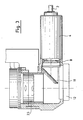
- the opening of the diaphragm (13) is adjusted via the lever (14) shown in FIG. 2.
- a cylindrical ring (15) is rotatably arranged between the housing (4) and the holder (7).
- the rotary knob (16) shown in Fig. 2 is used to rotate the ring (15). This actuation takes place via a bevel gear (17), which rotates the ring (15) about the optical axis (5) via an external thread (25) when the knob (16) is rotated.
- the ring (15) contains a control groove (18) in which a roller (19) engages.
- a roller (19) engages.
- the knob (16) is turned, the ring (15) is turned.
- the holder (7) is displaced in the direction of the optical axis (5) via the control groove (18) and the roller (19), a fixing pin (20) in a straight groove (21) preventing the holder from rotating.
- the aperture adjusting lever (14) engages, as can be seen in FIG. 2, in a groove (22) in the ring (15). As a result, when the rotary knob (16) is actuated and the ring (15) is rotated, the actuating lever (14) is pivoted and the opening of the diaphragm (13) is thus adjusted.
- the device shown in FIGS. 1 and 2 is fastened between the main objective (12) and the pancratic system (23) of the surgical microscope which is only partially shown in FIG. 3.
- the light guide (2) is first adjusted by axially displacing its holder (3) so that the desired illumination of the operating field is achieved.
- the surgical field is illuminated in a uniform manner or, for example, in the center.
- the selected type of illumination of the surgical field is fixed by tightening the screw (6) and remains in place when the socket (7) and thus the optical system (8, 9) and the diaphragm (13) are axially displaced.
- the control groove (18) can be designed such that initially only the opening of the diaphragm (13) is adjusted while there is still no axial displacement of the socket (7). From a predetermined aperture opening, the frame (7) is then displaced in the direction of the optical axis (5) and at the same time the aperture opening is adjusted.
- the aperture is adjusted from the outset and at the same time the socket (7) is axially displaced.
- the actuation of the diaphragm (13) and the axial displacement of the socket (7) can be combined in any desired manner by appropriately designing the control groove (18).
Abstract
Description
- Die Erfindung betrifft eine Beleuchtungseinrichtung für Operationsmikroskope mit einem Hauptobjektiv für die beiden stereoskopischen Beobachtungsstrahlengänge und mit einer Lichtquelle, welcher ein Lichtleiter nachgeordnet ist.
- Bei Operationen im Bereich der Hals-Nasen-Ohren-Medizin, der Neurologie und der Gynäkologie werden Operationsmikroskope benötigt, die eine Einstellung sowohl großer als auch sehr kleiner Leuchtfelder erlauben.
- Aus dem DE-GM 87 13 356.3 ist eine Beleuchtungseinrichtung für Operationsmikroskope bekannt, die es erlaubt, mit einem unveränderlichen Optiksystem unterschiedliche Leuchtfelddurchmesser zu realisieren. Nachteilig bei dieser bekannten Beleuchtungseinrichtung ist, daß ihr Dehnungsfaktor den operationsspezifischen Anforderungen nicht voll genügt.
- Der Erfindung liegt die Aufgabe zugrunde, eine Beleuchtungseinrichtung für Operationsmikroskope mit einem genügend großen, den operationsspezifischen Anforderungen voll entsprechendem Dehnungsfaktor des Leuchtfeldes anzugeben.
- Diese Aufgabe wird erfindungsgemäß dadurch gelöst, daß zwischen dem Hauptobjektiv des Operationsmikroskopes und der Lichtaustrittsfläche des Lichtleiters der Beleuchtungseinrichtung ein entlang der optischen Achse verschiebbares System vorgesehen ist, das aus einer Sammellinse und einer asphärischen Linse sowie einer Blende besteht.
- In einem vorteilhaften Ausführungsbeispiel der Erfindung besteht zwischen dem Durchmesser der Blende, dem Verschiebeweg des optischen Systems und dem eingestellten Leuchtfelddurchmesser eine lineare Korrelation, die beispielsweise durch einen getriebegesteuerten Verschiebemechanismus bewirkt wird.
- Durch einen kurvengesteuerten Verschiebemechanismus kann in einem anderen Ausführungsbeispiel zwischen den oben genannten Beleuchtungsparametern eine nichtlineare Korrelation hergestellt werden. Dabei wird die Einstellung der Beleuchtung vorteilhaft so vorgenommen, daß zunächst die Blende teilweise geöffnet wird und daß bei der weiteren Öffnung der Blende diese zusammen mit dem optischen System axial verschoben wird.
- Zweckmäßig ist die Beleuchtungseinrichtung so ausgebildet, daß zur Justierung der Lichtleiter relativ zur Blende verschoben werden kann. Damit läßt sich die Ausleuchtung des Objektfeldes wahlweise homogen oder mittenbetont einstellen, wobei diese Einstellung bei der Wahl der Größe des ausgeleuchteten Feldes erhalten bleibt.
- Die mit der Erfindung erzielten Vorteile bestehen insbesondere darin, daß das Beleuchtungssystem extrem kurzbauend ist, auch bei großen Leuchtfeldern eine gewünschte Ausleuchtung liefert und bei kleinen Leuchtfeldern eine gute Randschärfe sowie eine hohe Beleuchtungsstärke garantiert, was insbesondere bei Operationen in engen Kanälen bedeutsam ist, weil in diesen Fällen das von zu großen Leuchtfeldern verursachte Streulicht den Kontrast im Arbeitsfeld verschlechtert.
- Ein Ausführungsbeispiel der Erfindung ist in den Figuren 1 - 3 der beigefügten Zeichnung dargestellt und wird im folgenden näher beschrieben.
- Es zeigen
- Figur 1 einen Schnitt durch die nach der Erfindung ausgebildete Beleuchtungseinrichtung;
- Figur 2 einen Schnitt entlang der Linie II-II der Fig. 1;
- Figur 3 die Anordnung der Beleuchtungseinrichtung nach Fig. 1 an einem Operationsmikroskop.
- In Fig. 1 ist mit (2) ein Faserlichtleiter bezeichnet, in den das Licht einer nicht eingezeichneten Lichtquelle eingespeist ist. Der Lichtleiter (2) ist in einem zylindrischen Gehäuse (3) gefaßt, das im Gehäuse (4) angeordnet ist. Zu Justierzwecken ist der Lichtleiter (2) mit seinem Gehäuse (3) in Richtung der optischen Achse (5) verschiebbar, wobei die Schraube (6) zur Fixierung der Justiereinstellung dient.
- Im Gehäuse (4) ist eine Fassung (7) in Richtung der optischen Achse (5) verschiebbar gelagert. Die Fassung (7) enthält ein optisches System, bestehend aus einer Sammellinse (8) und einer asphärischen Linse (9). Dieses System bildet die Lichtaustrittsfläche (10) des Lichtleiters (2) über einen Umlenkspiegel (11) und das aus Fig. 3 ersichtliche Hauptobjektiv (12) des Operationsmikroskops auf das Operationsfeld ab.
- Die Fassung (7) enthält das optische System (8, 9) sowie eine Blende (13). Diese Blende kann als Kreisblende oder als Spaltblende oder als kombinierte Kreis-Spaltblende ausgeführt sein. Über den in Fig. 2 dargestellten Hebel (14) wird die Öffnung der Blende (13) verstellt.
- Zwischen dem Gehäuse (4) und der Fassung (7) ist ein zylindrischer Ring (15) drehbar angeordnet. Der in Fig. 2 dargestellte Drehknopf (16) dient zur Drehung des Ringes (15). Diese Betätigung erfolgt über ein Kegelradgetriebe (17), das über ein Außengewinde (25) bei einer Drehung des Knopfes (16) den Ring (15) um die optische Achse (5) dreht.
- Der Ring (15) enthält eine Steuernut (18), in die eine Rolle (19) eingreift. Bei einer Drehung des Knopfes (16) wird der Ring (15) gedreht. Über die Steuernut (18) und die Rolle (19) wird dabei die Fassung (7) in Richtung der optischen Achse (5) verschoben, wobei ein Fixierstift (20) in einer geraden Nut (21) eine Drehbewegung der Fassung verhindert.
- Der Blenden-Einstellhebel (14) greift, wie aus Fig. 2 ersichtlich ist in eine Nut (22) im Ring (15) ein. Dadurch wird bei einer Betätigung des Drehknopfes (16) und der damit bewirkten Drehung des Ringes (15) der Betätigungshebel (14) geschwenkt und damit die Öffnung der Blende (13) verstellt.
- Die in den Fig. 1 und 2 dargestellte Vorrichtung wird, wie Fig. 3 zeigt, zwischen dem Hauptobjektiv (12) und dem pankratischen System (23) des in Fig. 3 nur teilweise dargestellten Operationsmikroskopes befestigt.
- Danach wird zunächst der Lichtleiter (2) durch Axialverschiebung seiner Fassung (3) so justiert, daß die gewünschte Ausleuchtung des Operationsfeldes erreicht wird. Je nach dem eingestellten Abstand der Lichtaustrittsfläche (11) von der Blende (13) wird das Operationsfeld gelichmäßig oder zum Beispiel mittenbetont ausgeleuchtet. Die einmal gewählte Art der Ausleuchtung des Operationsfeldes, wird durch Anziehen der Schraube (6) fixiert und bleibt bei der Axialverschiebung der Fassung (7) und damit des optischen Systems (8, 9) und der Blende (13) erhalten.
- Zur Einstellung der Größe des ausgeleuchteten Feldes wird der Drehknopf (16) betätigt. Dadurch wird der Ring (15) gedreht und damit das optische System (8, 9) zusammen mit der Blende (13) in Richtung der optischen Achse (5) verschoben. Zugleich wird über den Einstellhebel (14) und die Nut (22) die Öffnung der Blende (13) verstellt.
- Die Steuernut (18) kann so ausgebildet sein, daß zunächst nur die Öffnung der Blende (13) verstellt wird, während noch keine Axialverschiebung der Fassung (7) erfolgt. Ab einer vorbestimmten Blendenöffnung wird dann die Fassung (7) in Richtung der optischen Achse (5) verschoben und zugleich die Blendenöffnung verstellt.
- Bei einer anderen Ausbildung der Steuernut (18) wird von vornherein die Blendenöffnung verstellt und zugleich die Fassung (7) axial verschoben. Durch entsprechende Ausbildung der Steuernut (18) lassen sich die Betätigung der Blende (13) und die Axialverschiebung der Fassung (7) in jeder gewünschten Weise kombinieren.
Claims (6)
Applications Claiming Priority (2)
| Application Number | Priority Date | Filing Date | Title |
|---|---|---|---|
| DE3833877 | 1988-10-05 | ||
| DE3833877A DE3833877A1 (de) | 1988-10-05 | 1988-10-05 | Beleuchtungseinrichtung fuer operationsmikroskope |
Publications (3)
| Publication Number | Publication Date |
|---|---|
| EP0364794A2 true EP0364794A2 (de) | 1990-04-25 |
| EP0364794A3 EP0364794A3 (de) | 1991-07-24 |
| EP0364794B1 EP0364794B1 (de) | 1994-06-08 |
Family
ID=6364439
Family Applications (1)
| Application Number | Title | Priority Date | Filing Date |
|---|---|---|---|
| EP89118125A Expired - Lifetime EP0364794B1 (de) | 1988-10-05 | 1989-09-29 | Beleuchtungseinrichtung für Operationsmikroskope |
Country Status (4)
| Country | Link |
|---|---|
| US (1) | US4998810A (de) |
| EP (1) | EP0364794B1 (de) |
| JP (1) | JP2837193B2 (de) |
| DE (3) | DE3833877A1 (de) |
Cited By (2)
| Publication number | Priority date | Publication date | Assignee | Title |
|---|---|---|---|---|
| EP0482340A1 (de) * | 1990-10-26 | 1992-04-29 | American Cyanamid Company | Beleuchtungsanordnung für Mikroskope mit variabler Blende |
| EP0483618A1 (de) * | 1990-11-02 | 1992-05-06 | Becton, Dickinson and Company | Sofortindikator für den Veneneintritt einer intravenösen Nadel |
Families Citing this family (13)
| Publication number | Priority date | Publication date | Assignee | Title |
|---|---|---|---|---|
| US5735290A (en) | 1993-02-22 | 1998-04-07 | Heartport, Inc. | Methods and systems for performing thoracoscopic coronary bypass and other procedures |
| DE4231468A1 (de) * | 1992-09-19 | 1994-03-24 | Leica Mikroskopie & Syst | Mikroskopstativfuß |
| US6494211B1 (en) | 1993-02-22 | 2002-12-17 | Hearport, Inc. | Device and methods for port-access multivessel coronary artery bypass surgery |
| US5957832A (en) * | 1993-10-08 | 1999-09-28 | Heartport, Inc. | Stereoscopic percutaneous visualization system |
| US5588949A (en) * | 1993-10-08 | 1996-12-31 | Heartport, Inc. | Stereoscopic percutaneous visualization system |
| CH693804A5 (de) * | 1994-10-13 | 2004-02-13 | Zeiss Carl Fa | Beleuchtungseinrichtung für ein Stereomikroskop. |
| DE19638263B4 (de) * | 1996-09-19 | 2004-01-29 | Carl Zeiss | Ophthalmologisches Beobachtungsgerät |
| US6251101B1 (en) | 1998-06-26 | 2001-06-26 | Visx, Incorporated | Surgical laser system microscope with separated ocular and objective lenses |
| US6195203B1 (en) | 1999-09-01 | 2001-02-27 | The United States Of America As Represented By The Administrator Of The National Aeronautics And Space Administration | Apparatus for direct optical fiber through-lens illumination of microscopy or observational objects |
| US6488398B1 (en) * | 2000-10-23 | 2002-12-03 | Optical Gaging Products, Inc. | Variable F/number substage illuminator for multiple magnification and zoom telecentric system |
| DE10202870A1 (de) * | 2002-01-11 | 2003-09-04 | Zeiss Carl Jena Gmbh | Beleuchtungseinrichtung für Mikroskope |
| US7130507B2 (en) * | 2002-10-18 | 2006-10-31 | Exfo Photonic Solutions Inc. | Light source unit for use with a light guide and lamp mounting arrangement |
| DE102007054686B4 (de) * | 2007-11-14 | 2017-07-20 | Carl Zeiss Meditec Ag | Operationsmikroskop mit Beleuchtungssystem und Beleuchtungssystem-Steuereinheit |
Citations (6)
| Publication number | Priority date | Publication date | Assignee | Title |
|---|---|---|---|---|
| DE3200938A1 (de) * | 1982-01-14 | 1983-07-21 | Laaber Faseroptik GmbH, 6090 Rüsselsheim | Faseroptische mehrpunktleuchte mit variabler brennweite |
| US4511223A (en) * | 1981-06-19 | 1985-04-16 | Nippon Kogaku K.K. | Telecentric variable power illumination system |
| DE3516271A1 (de) * | 1985-05-07 | 1986-11-13 | J.D. Möller Optische Werke GmbH, 2000 Wedel | Vario-projektions-anordnung zur operationsfeld-beleuchtung eines mikroskopes fuer die augen-operation |
| DE8713356U1 (de) * | 1987-10-05 | 1988-04-14 | Fa. Carl Zeiss, 7920 Heidenheim, De | |
| DE8802175U1 (de) * | 1988-02-19 | 1988-04-28 | Herbert Waldmann Gmbh & Co, 7730 Villingen-Schwenningen, De | |
| DE8802996U1 (de) * | 1988-02-04 | 1988-06-09 | Ernst Leitz Wetzlar Gmbh, 6330 Wetzlar, De |
Family Cites Families (3)
| Publication number | Priority date | Publication date | Assignee | Title |
|---|---|---|---|---|
| JPS5136623B2 (de) * | 1973-05-04 | 1976-10-09 | ||
| DE3147998A1 (de) * | 1981-12-04 | 1983-06-16 | Fa. Carl Zeiss, 7920 Heidenheim | Beleuchtungseinrichtung fuer mikroskope |
| DE3225479A1 (de) * | 1982-07-08 | 1984-01-12 | Fa. Carl Zeiss, 7920 Heidenheim | Durchlichtbeleuchtungseinrichtung |
-
1988
- 1988-10-05 DE DE3833877A patent/DE3833877A1/de not_active Withdrawn
- 1988-10-05 DE DE8817160U patent/DE8817160U1/de not_active Expired - Lifetime
-
1989
- 1989-09-29 DE DE58907825T patent/DE58907825D1/de not_active Expired - Lifetime
- 1989-09-29 EP EP89118125A patent/EP0364794B1/de not_active Expired - Lifetime
- 1989-10-02 US US07/416,059 patent/US4998810A/en not_active Expired - Lifetime
- 1989-10-05 JP JP1258971A patent/JP2837193B2/ja not_active Expired - Lifetime
Patent Citations (6)
| Publication number | Priority date | Publication date | Assignee | Title |
|---|---|---|---|---|
| US4511223A (en) * | 1981-06-19 | 1985-04-16 | Nippon Kogaku K.K. | Telecentric variable power illumination system |
| DE3200938A1 (de) * | 1982-01-14 | 1983-07-21 | Laaber Faseroptik GmbH, 6090 Rüsselsheim | Faseroptische mehrpunktleuchte mit variabler brennweite |
| DE3516271A1 (de) * | 1985-05-07 | 1986-11-13 | J.D. Möller Optische Werke GmbH, 2000 Wedel | Vario-projektions-anordnung zur operationsfeld-beleuchtung eines mikroskopes fuer die augen-operation |
| DE8713356U1 (de) * | 1987-10-05 | 1988-04-14 | Fa. Carl Zeiss, 7920 Heidenheim, De | |
| DE8802996U1 (de) * | 1988-02-04 | 1988-06-09 | Ernst Leitz Wetzlar Gmbh, 6330 Wetzlar, De | |
| DE8802175U1 (de) * | 1988-02-19 | 1988-04-28 | Herbert Waldmann Gmbh & Co, 7730 Villingen-Schwenningen, De |
Cited By (2)
| Publication number | Priority date | Publication date | Assignee | Title |
|---|---|---|---|---|
| EP0482340A1 (de) * | 1990-10-26 | 1992-04-29 | American Cyanamid Company | Beleuchtungsanordnung für Mikroskope mit variabler Blende |
| EP0483618A1 (de) * | 1990-11-02 | 1992-05-06 | Becton, Dickinson and Company | Sofortindikator für den Veneneintritt einer intravenösen Nadel |
Also Published As
| Publication number | Publication date |
|---|---|
| DE8817160U1 (de) | 1993-06-24 |
| DE58907825D1 (de) | 1994-07-14 |
| DE3833877A1 (de) | 1990-04-12 |
| EP0364794A3 (de) | 1991-07-24 |
| EP0364794B1 (de) | 1994-06-08 |
| JP2837193B2 (ja) | 1998-12-14 |
| US4998810A (en) | 1991-03-12 |
| JPH02156217A (ja) | 1990-06-15 |
Similar Documents
| Publication | Publication Date | Title |
|---|---|---|
| EP0364794B1 (de) | Beleuchtungseinrichtung für Operationsmikroskope | |
| DE2347914C3 (de) | Endoskop mit einer Bildübertragungs-Faseroptik und einem ersten und drehbaren zweiten Reflexionselement | |
| DE3442218C2 (de) | ||
| EP0661020B1 (de) | Schaltbare Beleuchtungseinrichtung für ein Operationsmikroskop | |
| DE19537868B4 (de) | Beleuchtungseinrichtung für ein Stereomikroskop | |
| EP1109046B1 (de) | Beleuchtungseinrichtung für ein Operationsmikroskop | |
| CH652217A5 (de) | Operationsmikroskop. | |
| CH624490A5 (de) | ||
| DE4237386A1 (en) | Lighting unit for use in surgical theatres - has fixed lens and second lens that can be axially positioned to adjust lighting zone | |
| DE4319502A1 (de) | Optische Vorrichtung | |
| DE19728035B4 (de) | Beobachtungsvorrichtung mit Schrägbeleuchtung | |
| DE4033151C2 (de) | Binokulares Fernglas | |
| EP0055209B1 (de) | Strahlenumlenkvorrichtung | |
| DE2219521A1 (de) | Einrichtung zur selbsttätigen Verwirklichung des Köhlerschen Beleuchtungsprinzips an Mikroskopen | |
| DE102005040834A1 (de) | Einrichtung zum Wechseln von Objektiven an optischen Geräten, insbesondere an Mikroskopen | |
| DE102004056531A1 (de) | Ergonomische Anordnung einer Probensteuerung | |
| DE3128642A1 (de) | Zoomobjektivaufbau | |
| EP0589177B1 (de) | Monokulares Fernrohr konstanter Länge | |
| EP0140836A2 (de) | Optisches Gerät zum Erzeugen eines visuellen stereoskopischen Bildes | |
| DD157757B1 (de) | Vorrichtung zur spaltbeleuchtung | |
| EP1410754A1 (de) | Operationsmikroskop mit einer Beleuchtungseinrichtung | |
| DE3207814C2 (de) | Objektiv | |
| DE2609202C2 (de) | Fokussiereinrichtung für einen Projektor | |
| DE19807119C1 (de) | Vorrichtung zur Positionierung | |
| EP0333637A2 (de) | Makroobjektiv mit einem am Objektivgehäuse drehbar gelagerten Entfernungsring |
Legal Events
| Date | Code | Title | Description |
|---|---|---|---|
| PUAI | Public reference made under article 153(3) epc to a published international application that has entered the european phase |
Free format text: ORIGINAL CODE: 0009012 |
|
| AK | Designated contracting states |
Kind code of ref document: A2 Designated state(s): CH DE FR IT LI |
|
| PUAL | Search report despatched |
Free format text: ORIGINAL CODE: 0009013 |
|
| AK | Designated contracting states |
Kind code of ref document: A3 Designated state(s): CH DE FR IT LI |
|
| 17P | Request for examination filed |
Effective date: 19911214 |
|
| 17Q | First examination report despatched |
Effective date: 19930903 |
|
| GRAA | (expected) grant |
Free format text: ORIGINAL CODE: 0009210 |
|
| AK | Designated contracting states |
Kind code of ref document: B1 Designated state(s): CH DE FR IT LI |
|
| PG25 | Lapsed in a contracting state [announced via postgrant information from national office to epo] |
Ref country code: IT Free format text: LAPSE BECAUSE OF FAILURE TO SUBMIT A TRANSLATION OF THE DESCRIPTION OR TO PAY THE FEE WITHIN THE PRESCRIBED TIME-LIMIT;WARNING: LAPSES OF ITALIAN PATENTS WITH EFFECTIVE DATE BEFORE 2007 MAY HAVE OCCURRED AT ANY TIME BEFORE 2007. THE CORRECT EFFECTIVE DATE MAY BE DIFFERENT FROM THE ONE RECORDED. Effective date: 19940608 Ref country code: FR Effective date: 19940608 |
|
| REF | Corresponds to: |
Ref document number: 58907825 Country of ref document: DE Date of ref document: 19940714 |
|
| EN | Fr: translation not filed | ||
| PLBE | No opposition filed within time limit |
Free format text: ORIGINAL CODE: 0009261 |
|
| STAA | Information on the status of an ep patent application or granted ep patent |
Free format text: STATUS: NO OPPOSITION FILED WITHIN TIME LIMIT |
|
| 26N | No opposition filed | ||
| PGFP | Annual fee paid to national office [announced via postgrant information from national office to epo] |
Ref country code: CH Payment date: 20080915 Year of fee payment: 20 |
|
| PGFP | Annual fee paid to national office [announced via postgrant information from national office to epo] |
Ref country code: DE Payment date: 20080919 Year of fee payment: 20 |
|
| REG | Reference to a national code |
Ref country code: CH Ref legal event code: PL |