EP0362719B1 - Heissluft-Handschweissgerät - Google Patents
Heissluft-Handschweissgerät Download PDFInfo
- Publication number
- EP0362719B1 EP0362719B1 EP89118122A EP89118122A EP0362719B1 EP 0362719 B1 EP0362719 B1 EP 0362719B1 EP 89118122 A EP89118122 A EP 89118122A EP 89118122 A EP89118122 A EP 89118122A EP 0362719 B1 EP0362719 B1 EP 0362719B1
- Authority
- EP
- European Patent Office
- Prior art keywords
- housing
- section
- commutator
- fan wheel
- air
- Prior art date
- Legal status (The legal status is an assumption and is not a legal conclusion. Google has not performed a legal analysis and makes no representation as to the accuracy of the status listed.)
- Expired - Lifetime
Links
- 238000003466 welding Methods 0.000 title claims abstract description 8
- OKTJSMMVPCPJKN-UHFFFAOYSA-N Carbon Chemical compound [C] OKTJSMMVPCPJKN-UHFFFAOYSA-N 0.000 claims abstract description 6
- 229910052799 carbon Inorganic materials 0.000 claims abstract description 6
- 238000010438 heat treatment Methods 0.000 claims description 10
- 229920002994 synthetic fiber Polymers 0.000 claims 2
- 239000004033 plastic Substances 0.000 abstract description 4
- 230000001681 protective effect Effects 0.000 description 15
- 238000001816 cooling Methods 0.000 description 3
- 239000002245 particle Substances 0.000 description 2
- 238000005299 abrasion Methods 0.000 description 1
- 210000000481 breast Anatomy 0.000 description 1
- 230000008878 coupling Effects 0.000 description 1
- 238000010168 coupling process Methods 0.000 description 1
- 238000005859 coupling reaction Methods 0.000 description 1
- 230000007547 defect Effects 0.000 description 1
- 239000011810 insulating material Substances 0.000 description 1
- 238000013021 overheating Methods 0.000 description 1
- 238000004904 shortening Methods 0.000 description 1
- 230000007704 transition Effects 0.000 description 1
Images

Classifications
-
- F—MECHANICAL ENGINEERING; LIGHTING; HEATING; WEAPONS; BLASTING
- F24—HEATING; RANGES; VENTILATING
- F24H—FLUID HEATERS, e.g. WATER OR AIR HEATERS, HAVING HEAT-GENERATING MEANS, e.g. HEAT PUMPS, IN GENERAL
- F24H3/00—Air heaters
- F24H3/02—Air heaters with forced circulation
- F24H3/04—Air heaters with forced circulation the air being in direct contact with the heating medium, e.g. electric heating element
- F24H3/0405—Air heaters with forced circulation the air being in direct contact with the heating medium, e.g. electric heating element using electric energy supply, e.g. the heating medium being a resistive element; Heating by direct contact, i.e. with resistive elements, electrodes and fins being bonded together without additional element in-between
- F24H3/0423—Air heaters with forced circulation the air being in direct contact with the heating medium, e.g. electric heating element using electric energy supply, e.g. the heating medium being a resistive element; Heating by direct contact, i.e. with resistive elements, electrodes and fins being bonded together without additional element in-between hand-held air guns
-
- B—PERFORMING OPERATIONS; TRANSPORTING
- B29—WORKING OF PLASTICS; WORKING OF SUBSTANCES IN A PLASTIC STATE IN GENERAL
- B29C—SHAPING OR JOINING OF PLASTICS; SHAPING OF MATERIAL IN A PLASTIC STATE, NOT OTHERWISE PROVIDED FOR; AFTER-TREATMENT OF THE SHAPED PRODUCTS, e.g. REPAIRING
- B29C65/00—Joining or sealing of preformed parts, e.g. welding of plastics materials; Apparatus therefor
- B29C65/02—Joining or sealing of preformed parts, e.g. welding of plastics materials; Apparatus therefor by heating, with or without pressure
- B29C65/10—Joining or sealing of preformed parts, e.g. welding of plastics materials; Apparatus therefor by heating, with or without pressure using hot gases (e.g. combustion gases) or flames coming in contact with at least one of the parts to be joined
-
- B—PERFORMING OPERATIONS; TRANSPORTING
- B29—WORKING OF PLASTICS; WORKING OF SUBSTANCES IN A PLASTIC STATE IN GENERAL
- B29C—SHAPING OR JOINING OF PLASTICS; SHAPING OF MATERIAL IN A PLASTIC STATE, NOT OTHERWISE PROVIDED FOR; AFTER-TREATMENT OF THE SHAPED PRODUCTS, e.g. REPAIRING
- B29C66/00—General aspects of processes or apparatus for joining preformed parts
- B29C66/80—General aspects of machine operations or constructions and parts thereof
- B29C66/81—General aspects of the pressing elements, i.e. the elements applying pressure on the parts to be joined in the area to be joined, e.g. the welding jaws or clamps
- B29C66/816—General aspects of the pressing elements, i.e. the elements applying pressure on the parts to be joined in the area to be joined, e.g. the welding jaws or clamps characterised by the mounting of the pressing elements, e.g. of the welding jaws or clamps
- B29C66/8167—Quick change joining tools or surfaces
-
- B—PERFORMING OPERATIONS; TRANSPORTING
- B29—WORKING OF PLASTICS; WORKING OF SUBSTANCES IN A PLASTIC STATE IN GENERAL
- B29C—SHAPING OR JOINING OF PLASTICS; SHAPING OF MATERIAL IN A PLASTIC STATE, NOT OTHERWISE PROVIDED FOR; AFTER-TREATMENT OF THE SHAPED PRODUCTS, e.g. REPAIRING
- B29C66/00—General aspects of processes or apparatus for joining preformed parts
- B29C66/80—General aspects of machine operations or constructions and parts thereof
- B29C66/84—Specific machine types or machines suitable for specific applications
- B29C66/861—Hand-held tools
Definitions
- the invention relates to a hot-air manual welding device with a plastic housing, which forms a rod-shaped handle part provided with air inlet openings, in which a commutator motor is fixed for driving an impeller, which is surrounded by a section of the housing which adjoins the handle part but has a larger diameter is to which, on the side facing away from the handle part, there is an end section which has a connecting device for a heating cartridge and a protective and connecting tube surrounding it.
- the commutator of the motor accommodated in the handle part is arranged on the side of the rotor facing the free end of the handle part the space for accommodating the carbon brushes interacting with the commutator is small. In the known devices, the carbon brush life is therefore relatively short.
- Another disadvantage is a relative great effort for the assembly of the commutator motor and the parts connected to it in the handle part of the housing. If an air quantity control is available, this is done by changing the opening of the air inlet openings provided in the handle part.
- the invention has for its object to provide a hot air manual welding device that is free of at least one of these defects of the known devices.
- the motor By arranging the impeller next to the commutator, the motor can be arranged in the housing such that the commutator and the associated brush apparatus lie in the section of the housing surrounding the impeller. Since this section can have a much larger diameter than the section forming the handle part and, in practice, also has, there is so much space available in the radial direction for the brush apparatus that brushes can be used which have a multiple of the service life in the known devices to have. The space is even sufficient to accommodate switch-off brushes, which lead to the device being switched off, provided the brush length has reached the minimum value that must not be undercut.
- the grip part is formed with two shells. This leads to a shorter assembly time.
- a design of the half-shells according to claim 3 also contributes to a shortening of the assembly time, because here there is no need to connect the motor and the other parts to be accommodated in the handle part to the handle part by means of screws.
- an air outlet opening is provided in the part of the housing surrounding the fan on the pressure side of the fan wheel, which can be opened more or less, but not completely closed.
- a protective body preferably connects to the end section of the housing according to claim 7
- Protective and connecting pipe on a part of its length surrounds at a distance. The operator can then support the hand that must press the nozzle against the welding point on this protective body.
- This protective body is expediently formed in one piece with a coupling ring, by means of which the protective and connecting tube is detachably connected to the housing.
- the protective and connecting tube and a nozzle connecting body are designed in accordance with claim 9.
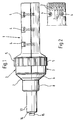
- a hot-air manual welding device has a plastic housing which, as shown in FIG. 1, forms a handle part 1 in the form of a cylindrical rod. At the free end of the handle part 1, as shown in FIG. 2, the housing is provided with air inlet openings 2. At the other end of the handle part 1 there is also a cylindrical section 3 of the housing, but with a much larger diameter. Both this section 3 and the handle part 1 are formed by two half-shells which are detachably connected to one another in the region of the handle part 1 and the section 3 by means of screws 4. Section 3 surrounds part of its length with a rubber ring 5 as a device support. On the side of the housing facing away from the handle part 1, there is an end section 6, between which and the section 3 a positive connection is present. As shown in FIG. 1, FIG.
- the end section 6 tapers conically towards its end facing away from section 3, where a thread is provided for the engagement of a union nut 7, which is followed by a tubular protective body 8 lying coaxially with it and the housing, which is formed in one piece with the union nut 7, which is also made of plastic.
- a bayonet connection could also be provided, for example.
- the end section 6 of the housing contains a socket 9 for receiving the plug pins 10 of a cylindrical heating cartridge 11 which is arranged coaxially with the housing and which in FIG Significant dimensions over the free end of the protective body 8 survives.
- An insulating sleeve 12 made of heat-insulating material is pushed onto the heating element 11 and protrudes somewhat beyond the free end of the heating cartridge.
- This insulating sleeve is surrounded by a metallic protective and connecting tube 13, which is provided at its end adjoining the end section 6 of the housing with a flange which is releasably clamped between the end section 6 and the union nut 7.
- the outer diameter of the protective and connecting tube 13 is selected so that it corresponds to the seat diameter of the known push-on nozzles. These can therefore be interchangeably attached to the free end section of the protective and connecting tube 13.
- a nozzle connecting body 14 is provided, the end section of which is reduced in diameter is provided with an external thread 15, onto which the known screw nozzles can be screwed.
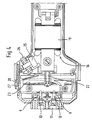
- a commutator motor 16 is fixed coaxially to the handle part 1 by a clamping action of the two half-shells, as shown in FIG. 3, in such a way that its commutator 20 and the brush holder 21 defined in the end shield lie in section 3 of the housing.
- the diametrically and radially arranged brush holder 21 can therefore be so long that it can accommodate carbon breasts with a service life that result in a long service life of the carbon brushes.
- the associated control resistor, formed by a potentiometer 25, is arranged, as shown in FIG. 4, in the region of the transition from the handle part 1 to the section 3 of the housing, which here has an opening which gives access to a setting wheel 26 which is firmly on the
- the shaft of the potentiometer 25 is arranged and can be easily operated with a finger that grips the handle part 21.
- the space between the outer circumferential surface of the stator 19 and the inner circumferential surface of the handle part 1 is, as shown in FIGS. 3 and 4, chosen so large that at least the majority of the air sucked in by the impeller 23 through the air inlet openings 2 via the control circuit 29, the Heat sink and the outer surface of the stator 19 flows, whereby it is achieved that particles entrained in the air do not flow fully over the commutator 20. This avoids an increase in brush abrasion.
- an air outlet opening 27 is provided in section 3 of the housing in the area in which the excess pressure generated by the impeller 23 prevails, which is arranged by means of a slide which is displaceable in the axial direction between the housing and the rubber ring 5 28 released and can be closed continuously up to a minimum cross-section.
- This minimum cross section is selected so that when no air can escape through the nozzle or the nozzle connecting body 14, there is still one for cooling the commutator motor 18 and the control circuit 24 required amount of air is sucked through the handle part 1 by the impeller 23.
Landscapes
- Engineering & Computer Science (AREA)
- Mechanical Engineering (AREA)
- Chemical & Material Sciences (AREA)
- Combustion & Propulsion (AREA)
- Physics & Mathematics (AREA)
- Thermal Sciences (AREA)
- General Engineering & Computer Science (AREA)
- Lining Or Joining Of Plastics Or The Like (AREA)
- Structures Of Non-Positive Displacement Pumps (AREA)
- Motor Or Generator Current Collectors (AREA)
- Arc Welding In General (AREA)
Priority Applications (1)
| Application Number | Priority Date | Filing Date | Title |
|---|---|---|---|
| AT89118122T ATE82546T1 (de) | 1988-10-04 | 1989-09-29 | Heissluft-handschweissgeraet. |
Applications Claiming Priority (2)
| Application Number | Priority Date | Filing Date | Title |
|---|---|---|---|
| DE3833677A DE3833677C1 (enExample) | 1988-10-04 | 1988-10-04 | |
| DE3833677 | 1988-10-04 |
Publications (3)
| Publication Number | Publication Date |
|---|---|
| EP0362719A2 EP0362719A2 (de) | 1990-04-11 |
| EP0362719A3 EP0362719A3 (en) | 1990-10-10 |
| EP0362719B1 true EP0362719B1 (de) | 1992-11-19 |
Family
ID=6364329
Family Applications (1)
| Application Number | Title | Priority Date | Filing Date |
|---|---|---|---|
| EP89118122A Expired - Lifetime EP0362719B1 (de) | 1988-10-04 | 1989-09-29 | Heissluft-Handschweissgerät |
Country Status (4)
| Country | Link |
|---|---|
| US (1) | US5023925A (enExample) |
| EP (1) | EP0362719B1 (enExample) |
| AT (1) | ATE82546T1 (enExample) |
| DE (1) | DE3833677C1 (enExample) |
Families Citing this family (10)
| Publication number | Priority date | Publication date | Assignee | Title |
|---|---|---|---|---|
| DE4119137C1 (en) * | 1991-06-11 | 1993-02-25 | Munsch Chemie-Pumpen Gmbh, 5412 Ransbach-Baumbach, De | Welding appts. for thermoplastic material - includes heatable advancing chamber, drive for an advancing element and air heater for pre-warmed air |
| DE4214813C2 (de) * | 1992-05-04 | 1994-02-24 | Daimler Benz Ag | Heißluft-Handschweißgerät zum manuellen Schweißen von thermoplastischen Kunststoffen |
| US5703604A (en) * | 1995-05-22 | 1997-12-30 | Dodeca Llc | Immersive dodecaherdral video viewing system |
| US5749704A (en) * | 1997-01-06 | 1998-05-12 | Wagner Spray Tech Corporation | Heat gun fan assembly |
| ATE313869T1 (de) * | 2003-09-18 | 2006-01-15 | Leister Process Tech | Bürstenloser elektromotor |
| DE502004009412D1 (de) * | 2004-03-15 | 2009-06-10 | Wegener Internat Gmbh | Handschweissgerät zum Verschweissen von Kunststoffwerkstücken |
| DE202007007282U1 (de) * | 2007-05-22 | 2008-10-02 | Leister Process Technologies | Extruderschweißeinrichtung |
| US20100008655A1 (en) * | 2008-03-07 | 2010-01-14 | Clint Tackitt | Hot air welding gun |
| CN204397850U (zh) * | 2015-01-14 | 2015-06-17 | 浙江普莱得电器有限公司 | 一种方便切换的多功能工具 |
| CN205986614U (zh) * | 2016-06-01 | 2017-02-22 | 浙江普莱得电器有限公司 | 设控制电路的有刷热风枪 |
Family Cites Families (6)
| Publication number | Priority date | Publication date | Assignee | Title |
|---|---|---|---|---|
| DE511589C (de) * | 1930-10-31 | Karl Ludwig Dipl Ing | Elektrischer Heissluftapparat | |
| US1821525A (en) * | 1929-10-11 | 1931-09-01 | Hamilton Beach Mfg Company | Hair drier |
| US2031391A (en) * | 1935-02-18 | 1936-02-18 | Black & Decker Electric Compan | Heat gun |
| US2478559A (en) * | 1947-01-08 | 1949-08-09 | George Wilson | Quick heat air blower and drying appliance |
| US4039774A (en) * | 1975-06-04 | 1977-08-02 | Sperry Rand Corporation | Portable hair dryer |
| GB8306199D0 (en) * | 1983-03-07 | 1983-04-13 | Skilten Electronics Ltd | Heated gas blower device |
-
1988
- 1988-10-04 DE DE3833677A patent/DE3833677C1/de not_active Expired
-
1989
- 1989-09-29 EP EP89118122A patent/EP0362719B1/de not_active Expired - Lifetime
- 1989-09-29 AT AT89118122T patent/ATE82546T1/de not_active IP Right Cessation
- 1989-10-03 US US07/416,476 patent/US5023925A/en not_active Expired - Fee Related
Also Published As
| Publication number | Publication date |
|---|---|
| DE3833677C1 (enExample) | 1989-07-27 |
| US5023925A (en) | 1991-06-11 |
| EP0362719A2 (de) | 1990-04-11 |
| EP0362719A3 (en) | 1990-10-10 |
| ATE82546T1 (de) | 1992-12-15 |
Similar Documents
| Publication | Publication Date | Title |
|---|---|---|
| DE69502648T2 (de) | Haushaltsdampfreinigungsgerät | |
| EP0362719B1 (de) | Heissluft-Handschweissgerät | |
| DE3734864C2 (de) | Zahnärztliches Spritzhandstück | |
| DE1557346C3 (de) | Haartrockner | |
| DE3002790C2 (de) | Halte- und Betätigungsvorrichtung für Spritzeinrichtungen von Hochdruckwaschanlagen | |
| DE69208870T2 (de) | Ein Kraftarbeitswerkzeug mit wählbaren Einlässen | |
| DE2440005A1 (de) | Vorrichtung zum erwaermen von gasfoermigen und/oder fluessigen stroemungsmedien | |
| DE2011697A1 (de) | Vorrichtung zum Löten und zum Trennen einer Verlötung | |
| DE202007007469U1 (de) | Fremdluftversorgtes Handschweißgerät | |
| DE1540862B1 (de) | Schweissgeraet fuer das schutzgas lichtbogenschweissen mit abschmelzender elektrode | |
| DE1300185B (de) | Induktionswerkzeug | |
| DE7915432U1 (de) | Teleskopierbarer fuehrungsstiel fuer haushaltsgeraete | |
| EP0283783A1 (de) | Elektrisches Lötgerät | |
| DE4143406C2 (de) | Ärtzliches, motorbetriebenes Behandlungsinstrument mit einem aus mindestens zwei Teilen bestehenden Handstück | |
| DE2304666C2 (de) | Druckluftbetriebenes chirurgisches Handstück | |
| EP0727173B1 (de) | Staubsaugerschlauch mit einem Griffstück | |
| DE2107526C3 (de) | Zahnärztliches Ultraschallgerät | |
| DE9310597U1 (de) | Akkubetriebenes Unterwasser-Elektrogerät in Modulbauweise | |
| AT391263B (de) | Zahnaerztliches handstueck | |
| DE10030034C1 (de) | Elektrisches Küchenhandgerät | |
| DE1616127B2 (enExample) | ||
| DE68910131T2 (de) | Heissgasschweisssystem. | |
| DE816007C (de) | Elektrisch beheizter Loetkolben | |
| DE877632C (de) | Stroemungsgekuehlter elektrischer Widerstand | |
| DE1557338C (de) | Heißluftaggregat |
Legal Events
| Date | Code | Title | Description |
|---|---|---|---|
| PUAI | Public reference made under article 153(3) epc to a published international application that has entered the european phase |
Free format text: ORIGINAL CODE: 0009012 |
|
| AK | Designated contracting states |
Kind code of ref document: A2 Designated state(s): AT BE CH DE ES FR GB GR IT LI LU NL SE |
|
| RBV | Designated contracting states (corrected) |
Designated state(s): AT CH FR GB IT LI SE |
|
| REG | Reference to a national code |
Ref country code: DE Ref legal event code: 8566 |
|
| PUAL | Search report despatched |
Free format text: ORIGINAL CODE: 0009013 |
|
| AK | Designated contracting states |
Kind code of ref document: A3 Designated state(s): AT BE CH DE ES FR GB GR IT LI LU NL SE |
|
| 17P | Request for examination filed |
Effective date: 19901218 |
|
| 17Q | First examination report despatched |
Effective date: 19920408 |
|
| GRAA | (expected) grant |
Free format text: ORIGINAL CODE: 0009210 |
|
| AK | Designated contracting states |
Kind code of ref document: B1 Designated state(s): AT CH FR GB IT LI SE |
|
| REF | Corresponds to: |
Ref document number: 82546 Country of ref document: AT Date of ref document: 19921215 Kind code of ref document: T |
|
| ET | Fr: translation filed | ||
| ITF | It: translation for a ep patent filed | ||
| GBT | Gb: translation of ep patent filed (gb section 77(6)(a)/1977) |
Effective date: 19920205 |
|
| PLBE | No opposition filed within time limit |
Free format text: ORIGINAL CODE: 0009261 |
|
| STAA | Information on the status of an ep patent application or granted ep patent |
Free format text: STATUS: NO OPPOSITION FILED WITHIN TIME LIMIT |
|
| 26N | No opposition filed | ||
| EAL | Se: european patent in force in sweden |
Ref document number: 89118122.4 |
|
| PGFP | Annual fee paid to national office [announced via postgrant information from national office to epo] |
Ref country code: CH Payment date: 19950810 Year of fee payment: 7 |
|
| PGFP | Annual fee paid to national office [announced via postgrant information from national office to epo] |
Ref country code: GB Payment date: 19950818 Year of fee payment: 7 |
|
| PGFP | Annual fee paid to national office [announced via postgrant information from national office to epo] |
Ref country code: SE Payment date: 19950824 Year of fee payment: 7 |
|
| PGFP | Annual fee paid to national office [announced via postgrant information from national office to epo] |
Ref country code: AT Payment date: 19950930 Year of fee payment: 7 |
|
| PG25 | Lapsed in a contracting state [announced via postgrant information from national office to epo] |
Ref country code: GB Effective date: 19960929 Ref country code: AT Effective date: 19960929 |
|
| PG25 | Lapsed in a contracting state [announced via postgrant information from national office to epo] |
Ref country code: SE Effective date: 19960930 Ref country code: LI Effective date: 19960930 Ref country code: CH Effective date: 19960930 |
|
| REG | Reference to a national code |
Ref country code: CH Ref legal event code: PL |
|
| GBPC | Gb: european patent ceased through non-payment of renewal fee |
Effective date: 19960929 |
|
| EUG | Se: european patent has lapsed |
Ref document number: 89118122.4 |
|
| PGFP | Annual fee paid to national office [announced via postgrant information from national office to epo] |
Ref country code: FR Payment date: 19970930 Year of fee payment: 9 |
|
| PG25 | Lapsed in a contracting state [announced via postgrant information from national office to epo] |
Ref country code: FR Free format text: LAPSE BECAUSE OF NON-PAYMENT OF DUE FEES Effective date: 19990531 |
|
| REG | Reference to a national code |
Ref country code: FR Ref legal event code: ST |
|
| PG25 | Lapsed in a contracting state [announced via postgrant information from national office to epo] |
Ref country code: IT Free format text: LAPSE BECAUSE OF NON-PAYMENT OF DUE FEES;WARNING: LAPSES OF ITALIAN PATENTS WITH EFFECTIVE DATE BEFORE 2007 MAY HAVE OCCURRED AT ANY TIME BEFORE 2007. THE CORRECT EFFECTIVE DATE MAY BE DIFFERENT FROM THE ONE RECORDED. Effective date: 20050929 |