EP0362307B1 - Mesurage de la temperature par ultrasons et application en spectroscopie optique et en calorimetrie - Google Patents
Mesurage de la temperature par ultrasons et application en spectroscopie optique et en calorimetrie Download PDFInfo
- Publication number
- EP0362307B1 EP0362307B1 EP89902017A EP89902017A EP0362307B1 EP 0362307 B1 EP0362307 B1 EP 0362307B1 EP 89902017 A EP89902017 A EP 89902017A EP 89902017 A EP89902017 A EP 89902017A EP 0362307 B1 EP0362307 B1 EP 0362307B1
- Authority
- EP
- European Patent Office
- Prior art keywords
- ultrasonic
- resonator
- temperature
- measuring material
- light
- Prior art date
- Legal status (The legal status is an assumption and is not a legal conclusion. Google has not performed a legal analysis and makes no representation as to the accuracy of the status listed.)
- Expired - Lifetime
Links
Images

Classifications
-
- G—PHYSICS
- G01—MEASURING; TESTING
- G01N—INVESTIGATING OR ANALYSING MATERIALS BY DETERMINING THEIR CHEMICAL OR PHYSICAL PROPERTIES
- G01N29/00—Investigating or analysing materials by the use of ultrasonic, sonic or infrasonic waves; Visualisation of the interior of objects by transmitting ultrasonic or sonic waves through the object
- G01N29/02—Analysing fluids
- G01N29/024—Analysing fluids by measuring propagation velocity or propagation time of acoustic waves
-
- G—PHYSICS
- G01—MEASURING; TESTING
- G01K—MEASURING TEMPERATURE; MEASURING QUANTITY OF HEAT; THERMALLY-SENSITIVE ELEMENTS NOT OTHERWISE PROVIDED FOR
- G01K11/00—Measuring temperature based upon physical or chemical changes not covered by groups G01K3/00, G01K5/00, G01K7/00 or G01K9/00
- G01K11/22—Measuring temperature based upon physical or chemical changes not covered by groups G01K3/00, G01K5/00, G01K7/00 or G01K9/00 using measurement of acoustic effects
-
- G—PHYSICS
- G01—MEASURING; TESTING
- G01N—INVESTIGATING OR ANALYSING MATERIALS BY DETERMINING THEIR CHEMICAL OR PHYSICAL PROPERTIES
- G01N25/00—Investigating or analyzing materials by the use of thermal means
- G01N25/20—Investigating or analyzing materials by the use of thermal means by investigating the development of heat, i.e. calorimetry, e.g. by measuring specific heat, by measuring thermal conductivity
- G01N25/48—Investigating or analyzing materials by the use of thermal means by investigating the development of heat, i.e. calorimetry, e.g. by measuring specific heat, by measuring thermal conductivity on solution, sorption, or a chemical reaction not involving combustion or catalytic oxidation
- G01N25/4806—Details not adapted to a particular type of sample
- G01N25/4813—Details not adapted to a particular type of sample concerning the measuring means
- G01N25/482—Details not adapted to a particular type of sample concerning the measuring means concerning the temperature responsive elements
-
- G—PHYSICS
- G01—MEASURING; TESTING
- G01N—INVESTIGATING OR ANALYSING MATERIALS BY DETERMINING THEIR CHEMICAL OR PHYSICAL PROPERTIES
- G01N29/00—Investigating or analysing materials by the use of ultrasonic, sonic or infrasonic waves; Visualisation of the interior of objects by transmitting ultrasonic or sonic waves through the object
- G01N29/22—Details, e.g. general constructional or apparatus details
- G01N29/32—Arrangements for suppressing undesired influences, e.g. temperature or pressure variations, compensating for signal noise
- G01N29/326—Arrangements for suppressing undesired influences, e.g. temperature or pressure variations, compensating for signal noise compensating for temperature variations
-
- G—PHYSICS
- G01—MEASURING; TESTING
- G01N—INVESTIGATING OR ANALYSING MATERIALS BY DETERMINING THEIR CHEMICAL OR PHYSICAL PROPERTIES
- G01N2291/00—Indexing codes associated with group G01N29/00
- G01N2291/01—Indexing codes associated with the measuring variable
- G01N2291/011—Velocity or travel time
-
- G—PHYSICS
- G01—MEASURING; TESTING
- G01N—INVESTIGATING OR ANALYSING MATERIALS BY DETERMINING THEIR CHEMICAL OR PHYSICAL PROPERTIES
- G01N2291/00—Indexing codes associated with group G01N29/00
- G01N2291/01—Indexing codes associated with the measuring variable
- G01N2291/012—Phase angle
-
- G—PHYSICS
- G01—MEASURING; TESTING
- G01N—INVESTIGATING OR ANALYSING MATERIALS BY DETERMINING THEIR CHEMICAL OR PHYSICAL PROPERTIES
- G01N2291/00—Indexing codes associated with group G01N29/00
- G01N2291/01—Indexing codes associated with the measuring variable
- G01N2291/015—Attenuation, scattering
-
- G—PHYSICS
- G01—MEASURING; TESTING
- G01N—INVESTIGATING OR ANALYSING MATERIALS BY DETERMINING THEIR CHEMICAL OR PHYSICAL PROPERTIES
- G01N2291/00—Indexing codes associated with group G01N29/00
- G01N2291/02—Indexing codes associated with the analysed material
- G01N2291/028—Material parameters
- G01N2291/02881—Temperature
Definitions
- the invention relates to a method and a device for measuring small changes in temperature in a gas, and their applications in optical spectroscopy and calorimetry.
- temperatures can be measured via thermal expansion (liquid thermometer, bimetal stretch marks), via the temperature dependence of the electrical resistance (resistance thermometer) or via the thermal voltage at the interface of different metals (thermocouple).
- thermal expansion liquid thermometer, bimetal stretch marks
- resistance thermometer temperature dependence of the electrical resistance
- thermal voltage at the interface of different metals thermocouple
- Other methods are based on the emission of electromagnetic radiation (infrared radiometer, pyrometer). These measurement methods are very well suited for the temperature determination of solids and liquids.
- gas temperatures are usually measured indirectly by bringing the gas into contact with a solid-state or liquid thermometer. Because of the poor thermal conductivity of Gases and the low thermal energy transfer from the gas to the thermometer make such temperature measurements relatively slow.
- the temperature of an enclosed gas can be determined via its pressure.
- the pressure fluctuations that occur with a periodic change in gas temperature can be detected, for example, with a high sensitivity using a microphone.
- the temperature changes that occur are generally very small, so that the microphone would have to be operated at a lower frequency, in the subHz range.
- Microphones are not very suitable for such frequencies or even static measurements. It is therefore of interest to look for a method that allows a direct and quasi-static measurement of the gas temperature.
- Another application of a direct gas temperature measurement method is calorimetry.
- Calorimetric tests are carried out in a classic calorimeter in an aqueous environment.
- the sample is either brought directly into the water or it is immersed in the calorimeter water in a closed vessel.
- the latter is located in a water tank that is thermally separated from the surroundings as well as possible.
- the calorimetric analysis is based on the tracking of the temperature of this calorimeter water, to which the material to be measured releases its heat, for example by a chemical reaction. It should be noted that the temperature distribution within the calorimeter is as homogeneous as possible and that it also matches that of the measured material as closely as possible. An agitator is advantageously used for this purpose.
- the water is well suited as a heat transfer medium from the material to be measured to the thermometer: on the one hand because of its good thermal conductivity and on the other hand because of the quick accessibility of one homogeneous temperature distribution by stirring. In many cases, however, it is difficult or even impossible to place the reactor in the water bath of a calorimeter. For this reason, calorimetric measurements are often carried out in a gaseous environment (for example in air) or even in a vacuum, the measured material being placed on a base provided with temperature sensors, in the form of a plate or a crucible.
- the differential calorimeter should be mentioned.
- a gas calorimeter such as that used to determine heat of fusion and reaction
- Two crucibles are arranged on a plate in a cavity.
- One is the reactive, solid or liquid material to be measured and the other is an inert reference material.
- a thermocouple is in thermal contact with the two crucibles.
- the calorimeter cavity can be heated and may be surrounded by a heat insulation layer to shield external heat sources.
- thermocouple at the measured material contact point, compared to that at the reference material, a thermal voltage that provides information about the relative heating of the measured material.
- thermocouple wires be used to suppress unwanted heat dissipation, because the heat conduction of metals is about 4 orders of magnitude greater than that of the air.
- the thermal contact between the thermally poorly conductive glass rod and the thermocouple measuring point also poses problems. In general, thermal contacting of fine samples requires great effort - for example if the thermocouple has to be vapor-deposited to ensure good thermal contact. In addition, a metallic thermal connection cannot be realized in certain cases of very fine optoelectronic components if, for example, the optical properties are disturbed by the temperature sensor.
- the object is achieved by measuring the temperature-related detuning of an ultrasound resonator, which is formed by two ultrasound transducers arranged opposite one another, one operated as a transmitter and the other as a receiver.
- the object is achieved in that the temperature measurement method mentioned is used for temperature measurement in optical spectroscopy and calorimetry, in that the heat given off by the sample to the surrounding gas or absorbed by it is determined via the changes in the gas temperature.
- the physical principle of the proposed solution to the problem is based on the temperature dependence of the speed of sound. This effect is quite big.
- the speed of sound in air changes when the temperature rises from 25 ° C to 26 ° C from 340 m / sec to 340.6 m / sec, i.e. by 0.6 m / sec C or by approx. 0.5% per degree temperature change.
- the speed of sound c in a gas is calculated using the following formula:
- thermodynamic properties of air at room temperature do not differ significantly from those of an ideal gas, the measurement of variations in the speed of sound means a largely pressure-independent determination of gas temperature changes.
- the speed of sound can be determined, for example, from the time delay between the transmission of a pulse and the return of its echo.
- Another sound velocity measuring method which has been described by H. Rump in German published patent application DE 31 08 756 A1, consists in using two ultrasound transducers which are arranged opposite one another. The transit time of ultrasound pulses originating from one transducer was measured using the second transducer. The speed of sound of the gas located between the transducers can be determined based on the time difference. It was thus possible to infer the gas temperature with a known gas composition and the composition of a gas mixture with a known temperature. In order to increase the accuracy of the sound velocity measurement, it was proposed to measure the sound level on in addition to the transit time measurement Ultrasound receiver and to correlate the two measurements.
- An alternative method for measuring small changes in the speed of sound in a gas is the subject of the present invention.
- the process is that the temperature fluctuations in the gas shaped environment of a heat-exchanging sample via the detuning of an ultrasound resonator, which is formed from two ultrasound transducers arranged opposite one another.
- the advantage of this method compared to the previous one is that the sample does not have to have a high sound reflectivity - the sample can even be gaseous.
- the new method can only be used to examine samples that do not interfere with the ultrasonic field.
- the photothermal method therefore has advantages over the photoacoustic method where there are large pressure fluctuations.
- the photoacoustic method has a sensitivity that is approximately 50 times higher.
- thermodynamic variables are determined directly from the temperature profile of the air that surrounds the measured material.
- the ultrasound method allows the temperature of the gas that surrounds the material to be measured without causing local disturbances, such as through lead wires. It only has to be required that the measurement sample and the reference sample are in a comparable ultrasound field.
- the method presented is similar to that used to measure the optical absorption of thallium halides.
- the optical losses were determined photoacoustically by placing the measured material in a closed space and measuring the pressure changes caused by light absorption using a microphone (P. Horn, A. Schmidt and P. Braunlich, Jour. Quantum Electr., QE 19 , 1169 (1983)).
- the ultrasound method allows a local determination of temperature differences, while the entire heat released in the closed cavity is measured photoacoustically. Edge effects can thus be better eliminated if ultrasound is used.
- the photoacoustic method requires a high tightness of the calorimeter space - especially when working at a very low frequency. With the ultrasound method is only to strive for external gas flows not to affect the calorimeter space.
- FIG. 1 shows the structure of the already mentioned ultrasonic device for measuring small temperature fluctuations in a gas caused by absorption of infrared radiation.
- the gas temperature measurement method is based on the large temperature dependence of the speed of sound of gases.
- the same is measured by means of an ultrasound field, primarily in the form of an acoustic resonator 1.
- the acoustic resonance builds between the pair of ultrasound transducers, consisting of the ultrasound transmitter 2 and the ultrasound receiver 3.
- the ultrasound transmitter 2 is excited by the generator 4 at a frequency of typically several hundred kHz.
- the signal of the generator can be sinusoidal or consist of a regular sequence of, for example, rectangular pulses.
- a signal appears at the receiver 3, the envelope (peak-to-peak value) of which depends, in addition to the sensitivity of the receiver 3 and the sound absorption in the resonator chamber 1, on the tuning of the resonator 1.
- the receiver signal is fed to a device 5 - hereinafter referred to as an analyzer.
- This device 5 either analyzes the envelope of the received signal or determines the phase position of the signal with respect to the input signal at the transmitter 2. This analysis of the signal delivered by the receiver 3 is based, for example, on a peak-to-peak measurement, a rectification with subsequent smoothing, phase detection or phase-sensitive amplification using a lock-in amplifier.
- the ultrasound resonator is advantageously operated at the resonance maximum, ie in the area of the greatest phase change. Furthermore, the choice of the highest possible ultrasound frequency is recommended due to the fact that the envelope slope is largely proportional to the frequency.
- the upper limit of the ultrasound frequency is given by the sound absorption capacity of the sample gas, which rises sharply above 100 kHz with increasing frequency.
- the frequency can be selected higher than is possible with commercial air-adapted ultrasonic transducers (50 kHz to 220 kHz).
- the sound signal does not have to be transmitted efficiently over a distance of several meters or decimeters, as is normally desired, but only over a distance in the millimeter range.
- the change in the resonator tuning can now be directly related to the change in the signal envelope, i.e. the quasi-direct current value or the phase shift on the analyzer 5.
- the linear temperature measuring range is very limited in both cases.
- this restriction is not serious.
- slow drift-like temperature changes can cause the resonance tuning to drift and thus change the temperature sensitivity. It is therefore necessary to look for ways to counteract large long-term effects effectively.
- the ultrasound frequency can be tracked in such a way that the resonator tuning, that is to say the peak-to-peak value at the receiver 3, remains constant.
- the output signal of the analyzer 5 can be used as a control signal can be fed to a voltage-controlled generator 4 via a suitable controller 6.
- the temperature measurement range that can be covered is given by the operating range of the ultrasonic transducers.
- ultrasonic transducers can sweep 2, 3 frequency ranges from 1% to 2% of the target frequency.
- Temperature variations in the ultrasound resonator 1 can be achieved, for example, by light, in particular infrared radiation.
- Small temperature fluctuations in the ultrasonic resonator 1, which are caused by absorption of intensity-modulated light radiation and are therefore correlated with the light signal, can be measured, for example, by means of an analyzer 15 in the form of a lock-in amplifier.
- the latter uses the intensity-modulated signal from the light source 7 as a reference.
- the output signal of the analyzer 15 is the desired measured value, which provides information about the light absorption in the ultrasound resonator.
- This signal is therefore fed to a registration device 8, for example in the form of a recorder, a voltmeter or a computer input.
- the described method makes it possible to measure changes in gas temperature in the range of 10 degrees. More detailed information can be found in the previously mentioned articles by O. Oehler, J. Wieland and S.Friedrich.
- the ultrasound resonator 1 is arranged by the two ultrasound transducers 2, 3, which face each other are formed.
- the light from the source 7 passes through a window 11 into the ultrasound resonator 1 designed as a gas cuvette.
- At least one opening 22, 22 ' is present in the wall of the gas cuvette for exchanging the gaseous measurement material 20. If necessary, the openings are provided with flow resistances 23, 23 '. These flow resistances can valves, pipe constrictions 23 or filter plates 23 ', respectively. gas permeable membranes.
- the ultrasonic resonator 1 To prevent undesirable temperature fluctuations in the ultrasonic resonator 1, it is recommended to surround the same with a jacket-shaped heat insulation 27 and / or, if necessary, to keep it at a constant temperature by means of a heater 28, a heater control unit 28 'and a thermal sensor 28'. It can also be advantageous to bring the gaseous measured material to the temperature of the ultrasonic resonator by heating the supply lines by means of the heating elements 38, 38 '.
- the light source 7 is intensity-modulated, which is achieved, for example, by switching the current on and off, or by means of a light chopper 18, which is located in the light beam 17 between the light source 7 and the ultrasound resonator 1.
- a light chopper 18 which is located in the light beam 17 between the light source 7 and the ultrasound resonator 1.
- an optical filter 11 ' may be arranged in the light beam 17.
- the insertion of such a filter is particularly indicated if the source 7 has a broadband spectrum, that is to say if, for example, the light source 7 is a thermal radiator.
- an optical bandpass filter 11 ' can generate sufficient monochromatic radiation, so that selective light absorption by gases in the cuvette is ensured.
- the device for selective detection of gases shown in FIGS. 1 and 2 can be used. Although the sensitivity is not as high as in a device based on the photoacoustic effect, the device in question has a practically vanishing susceptibility to pressure fluctuations and structure-borne noise.
- FIG. 3 shows an embodiment of a calorimeter based on an ultrasound resonator 1.
- the local temperature of a gas is measured.
- the measurement sample itself can be the same, or it can surround a fluid measurement sample.
- the absorption of light does not lead to a change in the gas temperature, but rather the thermal behavior of the measured material, for example a chemical reaction in a gas, an aerosol, or a liquid, which has been brought into the ultrasound resonator 1 is.
- the calorimeter device 30 in turn consists of the two ultrasonic transducers 2, 3, which are laterally delimiting the ultrasonic resonator 1 and are arranged opposite one another.
- the ultrasonic transducer used as transmitter 2 is connected to an oscillator 4 and is excited by the same.
- the receiving ultrasound transducer 3 outputs its output signal to the analyzer 5, where it is evaluated on the basis of an envelope or phase analysis.
- the tuning of the oscillator 4 is adjusted, for example, by means of the controller 6.
- the local temperature distribution in the vicinity of the material to be measured 24 is not disturbed by external influences. This can be achieved on the one hand by the fact that the calorimeter room is largely closed and is therefore not influenced by external air currents. On the other hand, it must be ensured that the inside walls of the calorimeter have a temperature that is as constant and uniform as possible. This can prevent unwanted convection currents within the calorimeter. For this purpose, it is advisable to surround the ultrasound resonator 1 and the ultrasound transducers 2, 3 with a jacket-shaped thermal insulation 27.
- the ultrasound resonator 1 It is also indicated to provide the ultrasound resonator 1 with a thermostatted heater 28. In analogy to the device of FIG. 2, the same, 28, controls the temperature of the ultrasonic resonator 1 by means of the heating control device 28 'and the thermal sensor 28'.
- the ultrasonic transmitter 2 represents a significant heat source. In order to create stationary thermal conditions, it is therefore appropriate to provide the ultrasonic transducers 2, 3, in particular the transmitter 2, with cooling systems 36, 36 ', for example in the form of cooling fins or Peltier elements .
- the impedance of the ultrasonic transducers 2, 3 depends slightly on the operating frequency - an impedance minimum occurs when resonating - the thermal load on the ultrasonic transducers 2, 3 is also slightly variable when the operating frequency changes.
- this can be done by means of a heater control device and thermal sensors.
- the gaseous or liquid fluid to be examined is entered, for example, via valves 32, 32 'and the feed lines 33, 33' into the reaction area 31 of the ultrasonic resonator 1.
- the same is optionally brought beforehand, for example by means of the heating elements 38, 38 ', which are fastened to the feed lines 33, 33', to the temperature prevailing in the interior of the ultrasonic resonator 1.
- a heating element 34 is used, which is operated via a feed device 34 '.
- calorimetric analysis of gases and aerosols using the described device should be an exception, since the speed of sound is not only dependent on the gas temperature, but also essentially on the type of gas. It is therefore not only the heat of the gas reaction that is measured, but also the gas composition in the reactor space.
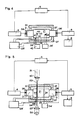
- Fig. 4 shows a calorimeter device which is suitable for investigations on solids and liquids.
- the device thus has a similar area of use as the differential scanning calorimeter mentioned. In contrast to this, however, it is not the temperature of the measured material 1 that is determined directly, but rather that of the surrounding gas.
- the material to be measured is not introduced directly into the ultrasound resonator via feed lines 33, 33 ', but is fixed mechanically in the ultrasound resonator 1.
- the solid material to be measured 40 does not have to be placed in a crucible 43, but can be fastened directly, for example by thin holders 41, 41 ', in the ultrasound resonator.
- These brackets can, for example, be electrical feed lines which trigger the reaction in the measured material 40.
- Liquids can, for example, be introduced into the ultrasonic resonator 1 via thin capillaries, which simultaneously take over the function of the holders 41, 41 '.
- the liquid material to be measured can either be present at the capillary tips or be in a small crucible 43.
- the other calorimeter components such as the reference heating element 34, the heaters 28, 37, 37 'of the ultrasonic resonator 1, respectively.
- the ultrasonic transducer 2, 3, the cooling 36, 36 'of the ultrasonic transducer and the thermally insulating jacket 27 of the calorimeter have already been described above.
- FIG. 5 shows a representation of a calorimeter for examining optical components.
- integrated optical and optoelectronic components such as light-guiding fibers, integrated optical light emitters, light receivers, optoelectronic light switches and connection points between optical components. It is only possible to distinguish the light absorption that occurs in the optical material from unwanted light scattering and light decoupling using thermal tests. The absorbed light output is converted into calorimetrically measurable heat, while the unwanted outcoupled light does not appear calorimetrically.
- Optimizing the optical components requires precise knowledge of the origin of the losses. For this reason, the optical losses in optical materials and components, such as glass fibers, have been calorimetrically measured in various ways.
- the optical loss in glass was determined by placing a glass rod in the optical resonator of a powerful laser and measuring the sample temperature increase during laser operation and the time constant of the temperature decrease after switching off the laser (TCRich and DA Pinnow , Appl. Phys. Lett. 20 , 264 (1972).
- the optical absorption of thallium halides was further determined photoacoustically by placing the measured material in a closed space and measuring the pressure changes caused by light absorption using a microphone (P. Horn, A. Schmid and P. Braunlich, Jour. Quantum Electr., QE 19 , 1169 (1983)).
- the light beam 51 is coupled into the optically conductive measured material 50 outside the calorimeter space 1 by means of the focusing optics 52 in the coupling area 53.
- the light coupled out on the opposite side of the ultrasonic resonator 1 in the area 54 from the optical element 50 is optionally fed to a light detector 55 after further focusing by means of the optics 52 '.
- the optical loss can be determined on the basis of the signal at this light detector 55.
- the calorimetric measurement is carried out either by measuring the gas temperature in the vicinity of the optically conductive element 50 before and after switching on the optical light coupling, or by coupling the light alternately into the measured material 50 at a very low frequency.
Landscapes
- Physics & Mathematics (AREA)
- Chemical & Material Sciences (AREA)
- General Physics & Mathematics (AREA)
- General Health & Medical Sciences (AREA)
- Life Sciences & Earth Sciences (AREA)
- Health & Medical Sciences (AREA)
- Analytical Chemistry (AREA)
- Biochemistry (AREA)
- Immunology (AREA)
- Pathology (AREA)
- Acoustics & Sound (AREA)
- Engineering & Computer Science (AREA)
- Chemical Kinetics & Catalysis (AREA)
- Combustion & Propulsion (AREA)
- Investigating Or Analyzing Materials By The Use Of Ultrasonic Waves (AREA)
- Investigating Or Analysing Materials By Optical Means (AREA)
Abstract
Claims (28)
- Procédé pour analyser thermiquement un matériau de mesure dans une atmosphère gazeuse, caractérisé en ce que- le matériau de mesure est placé dans la chambre à gaz d'un résonateur à ultrason,- le résonateur à ultrason est composé par deux transformateurs d'ultrason, placés l'un en face de l'autre, l'un travaillant comme émetteur, l'autre comme récepteur, et- la quantité de chaleur cédée du matériau de mesure à l'atmosphère gazeuse, respectivement reçue de l'atmosphère gazeuse par le matériau de mesure, est mesurée à l'aide de la variation de l'accord du résonateur à ultrason.
- Procédé selon la revendication 1, caractérisé en ce que la variation de l'accord du résonateur à ultrason est mesurée ou bien à l'aide du changement de l'amplitude du résonateur à ultrason travaillant dans un flanc de la résonance, ou bien à l'aide du changement de phase entre le signal ultrasonique émis et capté du résonateur à ultrason travaillant en proximité de la résonance.
- Procédé selon la revendication 2, caractérisé en ce qu'ils existent des moyens de réglage qui controllent l'accord du résonateur à ultrason.
- Procédé selon la revendication 2, caractérisé en ce que le matériau de mesure, placé dans le résonateur à ultrason est sousmis à un rayonnement de lumière modulée en intensité et au besoin monochromatique.
- Procédé selon la revendication 4, caractérisé en ce qu'ils existent des moyens pour échanger le matériau de mesure gazeux.
- Procédé selon la revendication 5, caractérisé en ce que le matériau de mesure se présente sous forme gazeuse et qu'en faisant entrer un rayonnement de lumière dans le résonateur à ultrason une analyse photothermique de gaz est effectuée.
- Procédé selon l'une des revendications 1 à 3, caractérisé en ce que le matériau de mesure est analysé de façon calorimétrique.
- Procédé selon la revendication 7, caractérisé en ce qu'on utilise une source de chaleur supplémentaire dans le résonateur à ultrason comme référence de chaleur.
- Procédé selon l'une des revendications 7 ou 8, caractérisé en ce que le matériau de mesure est un fluide liquide ou gazeux ou un mélange de fluides et que le fluide ou ses composants sont conduits avant ou pendant la mesure calorimétrique dans le résonateur à ultrason par au moins une conduite d'amené.
- Procédé selon l'une des revendications 7 ou 8, caractérisé en ce que le matériau de mesure est un corps solide placé dans le résonateur à ultrason.
- Procédé selon la revendication 7, caractérisé en ce que le matériau de mesure est alimenté de l'extérieur de manière continuelle ou alternante avec de l'énergie pendant l'analyse calorimétrique.
- Procédé selon la revendication 11, caractérisé en ce que le matériau de mesure est un élément apte à conduire la lumière, qui peut être alimenté avec de l'énergie sous forme de lumière.
- Procédé selon la revendication 11, caractérisé en ce que le matériau de mesure possède une conductibilité électrique supérieure à zéro et peut être alimenté avec de l'énergie électrique.
- Dispositif qui sert à analyser de façon thermique un matériau de mesure (20,50) placé dans une atmosphère gazeuse et qui est composé par une chambre séparée, appelée chambre calorimétrique (21), et par des moyens pour mesurer la température qui sert à déterminer la quantité de chaleur cédée du matériau de mesure (20,50) au gaz ambient, respectivement reçue par le matériau de mesure du gaz ambient, où- les moyens pour mesurer la température sont constitués par deux transformateurs d'ultrason (2,3), placés l'un en face de l'autre sur la paroi de la chambre calorimétrique (21), et- l'un (2) des deux transformateurs d'ultrason travaille comme émetteur, étant relié à un oscillateur, et l'autre (3) comme récepteur, étant relié à un analyseur (5),
caractérisé en ce que- les transformateurs d'ultrason (2,3) sont placés à une distance telle qu'ils constituent un résonateur à ultrason (1) et- qu'ils existent des moyens (6,12,16) pour mesurer l'accord du résonateur à ultrason. - Dispositif selon la revendication 14, caractérisé en ce que pour mesurer l'accord du résonateur à ultrason (1) le récepteur d'ultrason (3) est relié à un analyseur (5), qui détecte le changement de l'amplitude du signal ultrasonique, ou le changement de phase par rapport au signal transmis à l'émetteur d'ultrason (2).
- Dispositif selon la revendication 14 ou 15, caractérisé en ce que l'analyseur (5) est relié par un premier élément de réglage (6) à l'oscillateur (4) et/ou par un deuxième élément de réglage à un dispositif mécanique (12) servant à déplacer l'un des deux transformateurs d'ultrason.
- Dispositif selon l'une des revendications 14 à 16, caractérisé en ce que la chambre calorimétrique (21) possède une ouverture, couverte au besoin par une fenêtre (11) et qu'ils existent des moyens (22,22′,23,23′) pour échanger le gaz.
- Dispositif selon la revendication 17, caractérisé en ce qu'il existe un élément interrupteur servant à brancher et à débrancher le courant d'une source de lumière (7), ou qu'un hâcheur de lumière (18) se trouve dans le rayon lumineux (17) entre la source de lumière (7) et le résonateur à ultrason (1) et/ou qu'il se trouve un filtre optique (11′) dans le rayon lumineux (17).
- Dispositif selon la revendication 18, caractérisé en ce qu'il existe au moins une ouverture (22,22′) dans la paroi de la chambre calorimétrique (2) et que ces ouvertures sont au besoin munies de résistances de flux (23,23′) sous forme de clapets, de rétricissements de tuyeau (23) ou de plaques de filtre (23′).
- Dispositif selon l'une des revendications 14 à 16, caractérisé en ce qu'ils existent des moyens (34,34′,41,41′,52,52′), qui permettent de faire entrer ou sortir de l'énergie dans la chambre du résonateur (21).
- Dispositif selon la revendication 20, caractérisé en ce que en outre un élément de chauffage de référence (34) est placé entre les transformateurs d'ultrason (2,3) dans la chambre calorimétrique (21), cet élément étant relié à un appareil d'alimentation (34′).
- Dispositif selon l'une des revendications 20 ou 21, caractérisé en ce qu'il existe ou moins une conduite d'amené (33,33′) qui permet d'amener le matériau de mesure , sous forme d'un fluide gazeux ou liquide ou ses composants dans la chambre calorimétrique (21).
- Dispositif selon l'une des revendications 20 ou 21, caractérisé en ce qu'il existe au moins un élément de fixation (41,41′), qui fixe la matériau de mesure, sous forme d'un corps solide ou d'un liquide enfermé, dans la chambre calorimétrique (21).
- Dispositif selon la revendication 23, caractérisé en ce qu'il existe au moins un dispositif optique de focalisation (52,52′) qui permet de coupler et au besoin de découpler de la lumière dans le matériau de mesure sous forme d'un élément (50) apte à conduire la lumière.
- Dispositif selon les revendications 14 à 24, caractérisé en ce qu'ils existent des moyens, composés par un élément de chauffage (28), un appareil de contrôle de chauffage (28′) et d'un capteur thermique (28˝), qui permettent de maintenir la paroi de la chambre calorimétrique (21) à une température constante ou de changer celle-ci d'une façon donnée.
- Dispositif selon les revendications 14 à 24, caractérisé en ce qu'ils existent des moyens, composés par des éléments de chauffage (37,37′), un appareil de contrôle de chauffage et de capteurs thermiques et au besoin d'éléments de refroidissements (36,36′) qui permettent de maintenir au moins un transformateur d'ultrason (2,3) à une température constante ou de changer la température de celui-ci d'une façon donnée.
- Application du dispositif selon l'une des revendications 14 à 19 pour la détection sélective de gaz.
- Application du dispositif selon l'une des revendications 14 à 16 et 19 pour l'analyse calorimétrique des conducteurs de lumière.
Priority Applications (1)
| Application Number | Priority Date | Filing Date | Title |
|---|---|---|---|
| AT89902017T ATE83316T1 (de) | 1988-02-19 | 1989-02-17 | Ultraschall-temperaturmessung und anwendungen in der optischen spektroskopie und der kalorimetrie. |
Applications Claiming Priority (4)
| Application Number | Priority Date | Filing Date | Title |
|---|---|---|---|
| CH624/88 | 1988-02-19 | ||
| CH62488 | 1988-02-19 | ||
| CH491/89 | 1989-02-13 | ||
| CH49189 | 1989-02-13 |
Publications (2)
| Publication Number | Publication Date |
|---|---|
| EP0362307A1 EP0362307A1 (fr) | 1990-04-11 |
| EP0362307B1 true EP0362307B1 (fr) | 1992-12-09 |
Family
ID=25684727
Family Applications (1)
| Application Number | Title | Priority Date | Filing Date |
|---|---|---|---|
| EP89902017A Expired - Lifetime EP0362307B1 (fr) | 1988-02-19 | 1989-02-17 | Mesurage de la temperature par ultrasons et application en spectroscopie optique et en calorimetrie |
Country Status (3)
| Country | Link |
|---|---|
| US (1) | US5141331A (fr) |
| EP (1) | EP0362307B1 (fr) |
| WO (1) | WO1989007753A1 (fr) |
Families Citing this family (46)
| Publication number | Priority date | Publication date | Assignee | Title |
|---|---|---|---|---|
| US5296374A (en) * | 1989-10-20 | 1994-03-22 | University Of Strathclyde | Apparatus for assessing a particular property in a medium |
| GB8923699D0 (en) * | 1989-10-20 | 1989-12-06 | Univ Strathclyde | Apparatus for assessing a particular property in a medium |
| ATE109280T1 (de) * | 1989-12-08 | 1994-08-15 | Oehler Oscar | Selektive gasdetektion durch feldseparation und schallgeschwindigkeitsmessung: sauerstoff- detektion. |
| JP3224286B2 (ja) * | 1992-11-02 | 2001-10-29 | 株式会社日本自動車部品総合研究所 | 超音波を用いた温度測定装置 |
| US5581295A (en) * | 1992-11-27 | 1996-12-03 | Eastman Kodak Company | Method and apparatus for resequencing image data for a printhead |
| DE4309250A1 (de) * | 1993-03-23 | 1994-09-29 | Grau Gmbh & Co Holdingges | Datenträgerarchivsystem |
| DE4313216C2 (de) * | 1993-04-22 | 1995-12-14 | Max Planck Gesellschaft | Ultraschallmeßgerät mit mindestens einem nicht-piezoelektrischen Resonatorkammerkörper und außen angeordneten elektro-akustischen Wandlern |
| US5549387A (en) * | 1994-06-01 | 1996-08-27 | The Perkin-Elmer Corporation | Apparatus and method for differential analysis using real and imaginary signal components |
| ES2221925T3 (es) * | 1995-09-04 | 2005-01-16 | Siemens Building Technologies Ag | Sensor de gas fotoacustico y su utilizacion. |
| US5840023A (en) * | 1996-01-31 | 1998-11-24 | Oraevsky; Alexander A. | Optoacoustic imaging for medical diagnosis |
| US6309352B1 (en) | 1996-01-31 | 2001-10-30 | Board Of Regents, The University Of Texas System | Real time optoacoustic monitoring of changes in tissue properties |
| US6405069B1 (en) | 1996-01-31 | 2002-06-11 | Board Of Regents, The University Of Texas System | Time-resolved optoacoustic method and system for noninvasive monitoring of glucose |
| US5772322A (en) * | 1996-05-31 | 1998-06-30 | Honeywell Inc. | Resonant microbeam temperature sensor |
| EP0846261A1 (fr) * | 1996-06-22 | 1998-06-10 | Oscar Oehler | Syntonisation et etalonnage d'un dispositif photothermique de detection de gaz |
| US5768937A (en) * | 1996-11-13 | 1998-06-23 | Leybold Inficon, Inc. | Acoustic sensor for in-line continuous monitoring of gasses |
| US5894352A (en) * | 1997-05-20 | 1999-04-13 | Cymer, Inc. | Absorption tester for optical components |
| US5852308A (en) * | 1997-06-30 | 1998-12-22 | Honeywell Inc. | Micromachined inferential opto-thermal gas sensor |
| SE9704329D0 (sv) * | 1997-11-25 | 1997-11-25 | Siemens Elema Ab | Gasmätare |
| FR2772482B1 (fr) * | 1997-12-12 | 2000-03-03 | Centre Nat Rech Scient | Procede et dispositif pour le suivi de transitions de phase |
| FR2772476B1 (fr) * | 1998-03-31 | 2000-03-03 | Centre Nat Rech Scient | Procede et dispositif pour le suivi de transitions de phase |
| EP0967483A2 (fr) * | 1998-05-20 | 1999-12-29 | N.V. Nederlandse Gasunie | Méthode sans combustion pour la détermination de la valeur calorifique d'un gaz carburant |
| WO1999064846A1 (fr) * | 1998-06-12 | 1999-12-16 | Asahi Kasei Kogyo Kabushiki Kaisha | Analyseur |
| US6498942B1 (en) | 1999-08-06 | 2002-12-24 | The University Of Texas System | Optoacoustic monitoring of blood oxygenation |
| US6517240B1 (en) * | 1999-11-05 | 2003-02-11 | Durametrics, Inc. | Ultrasonic thermometer system |
| US6751490B2 (en) | 2000-03-01 | 2004-06-15 | The Board Of Regents Of The University Of Texas System | Continuous optoacoustic monitoring of hemoglobin concentration and hematocrit |
| SE0100379D0 (sv) * | 2001-02-07 | 2001-02-07 | Siemens Elema Ab | Arrangement for and method of acoustic determination of fluid temperature |
| GB2379743B (en) * | 2001-07-04 | 2005-05-25 | Amersham Pharm Biotech Uk Ltd | A method, a measuring cell and a system for measuring very small heat changes in a sample |
| US20030226401A1 (en) * | 2002-06-06 | 2003-12-11 | Howard Letovsky | Atomic structure recognition and modification method and apparatus |
| SE0300848D0 (sv) * | 2003-03-26 | 2003-03-26 | Siemens Elema Ab | Acoustic Analysis of Gas Mixtures |
| US7430445B2 (en) * | 2003-04-24 | 2008-09-30 | The Board Of Regents Of The University Of Texas System | Noninvasive blood analysis by optical probing of the veins under the tongue |
| EP1998161A1 (fr) * | 2007-05-29 | 2008-12-03 | The Technical University of Denmark (DTU) | Cellule de résonateur acoustique pour la mesure spectroscopique d'une substance dans un fluide |
| US7665891B1 (en) * | 2007-09-20 | 2010-02-23 | The United States Of America As Represented By The Administrator Of The National Aeronautics And Space Administration | Differential temperature sensor system and method |
| US8194246B2 (en) * | 2008-08-11 | 2012-06-05 | UT-Battellle, LLC | Photoacoustic microcantilevers |
| US7924423B2 (en) * | 2008-08-11 | 2011-04-12 | Ut-Battelle, Llc | Reverse photoacoustic standoff spectroscopy |
| US7961313B2 (en) * | 2008-08-11 | 2011-06-14 | Ut-Battelle, Llc | Photoacoustic point spectroscopy |
| US20110164652A1 (en) * | 2010-01-05 | 2011-07-07 | Refalo Lee A | Differential Thermoelectric Cooler Calorimeter |
| US8801277B2 (en) | 2010-01-15 | 2014-08-12 | University Of Utah Research Foundation | Ultrasonic temperature measurement device |
| US20110231966A1 (en) * | 2010-03-17 | 2011-09-22 | Ali Passian | Scanning probe microscopy with spectroscopic molecular recognition |
| US8448261B2 (en) | 2010-03-17 | 2013-05-21 | University Of Tennessee Research Foundation | Mode synthesizing atomic force microscopy and mode-synthesizing sensing |
| US8080796B1 (en) | 2010-06-30 | 2011-12-20 | Ut-Battelle, Llc | Standoff spectroscopy using a conditioned target |
| US9301876B2 (en) | 2011-05-16 | 2016-04-05 | Wavelight Gmbh | System and process for surgical treatment of an eye as well as process for calibrating a system of such a type |
| DE102011056533A1 (de) | 2011-12-16 | 2013-06-20 | WaveScape Technologies GmbH | Verfahren zur Messung einer Temperatur oder eines Abstandsmaßes |
| DE102012008102B3 (de) * | 2012-04-25 | 2013-08-01 | Testo Ag | Messvorrichtung und Messverfahren |
| CN103760108B (zh) * | 2013-12-30 | 2017-01-25 | 浙江大学 | 一种湿蒸汽湿度的光声差动测量方法与装置 |
| CN105403323B (zh) * | 2015-12-31 | 2018-03-27 | 中国空气动力研究与发展中心计算空气动力研究所 | 一种基于相位检测的结构内部温度场测量方法 |
| US10697875B2 (en) * | 2017-01-26 | 2020-06-30 | THE CURATORS OF THE UNIVERSITY OF MlSSOURI | System and method for in-situ measurement of viscoelastic material properties using continuous-wave ultrasound |
Family Cites Families (18)
| Publication number | Priority date | Publication date | Assignee | Title |
|---|---|---|---|---|
| US3303340A (en) * | 1963-10-25 | 1967-02-07 | Gen Electric | Optical arrangement in hot box detection apparatus |
| US3468157A (en) * | 1966-03-03 | 1969-09-23 | Phillips Petroleum Co | Acoustical apparatus for detecting the composition of a gas |
| US3513699A (en) * | 1967-11-09 | 1970-05-26 | Atomic Energy Commission | Adiabatic calorimeter |
| US3667297A (en) * | 1969-05-21 | 1972-06-06 | Us Army | Flueric temperature sensor |
| US3762197A (en) * | 1970-09-14 | 1973-10-02 | Phillips Petroleum Co | Acoustical detecting apparatus |
| DE2433764A1 (de) * | 1974-07-13 | 1976-01-22 | Monforts Fa A | Vorrichtung zum bestimmen des mischungsverhaeltnisses von binaeren gasen |
| JPS54134479A (en) * | 1978-04-10 | 1979-10-18 | Sharp Corp | Wireless temperature measuring device |
| JPS6010249B2 (ja) * | 1978-04-26 | 1985-03-15 | 株式会社日本自動車部品総合研究所 | 超音波温度計 |
| US4175423A (en) * | 1978-05-01 | 1979-11-27 | Sun Oil Company (Delaware) | Apparatus for determining the pulse repetition rate of a fluidic oscillator through which a test gas is flowing |
| NO791305L (no) * | 1978-08-04 | 1980-02-05 | Sub Sea Oil Services Ssos | Gassanalysator |
| DE2854577C2 (de) * | 1978-12-18 | 1986-05-15 | Krupp Koppers GmbH, 4300 Essen | Verfahren und Einrichtung zur Messung der Temperatur in Brennkammern oder anderen gasgefüllten Kammern |
| US4265125A (en) * | 1979-08-02 | 1981-05-05 | Mahany Richard J | Flowmeter method and apparatus |
| JPS56147027A (en) * | 1980-04-15 | 1981-11-14 | Toshiba Corp | Temperature detector for high-frequency heater |
| DE3108756A1 (de) * | 1981-03-07 | 1982-11-25 | Hanns 4750 Unna-Massen Rump | Verfahren und apparat zur bestimmung der schallgeschwindigkeit in gasen zum zwecke der bestimmung der temperatur bekannter gase bzw. der zusammensetzung binaerer gasgemische bekannter temperatur |
| US4708494A (en) * | 1982-08-06 | 1987-11-24 | Marcos Kleinerman | Methods and devices for the optical measurement of temperature with luminescent materials |
| US4683750A (en) * | 1984-11-07 | 1987-08-04 | The Board Of Trustees Of The Leland Stanford Junior University | Thermal acoustic probe |
| JPS6383625A (ja) * | 1986-09-27 | 1988-04-14 | Nippon Steel Corp | 高温物体の温度測定方法 |
| US4848924A (en) * | 1987-08-19 | 1989-07-18 | The Babcock & Wilcox Company | Acoustic pyrometer |
-
1989
- 1989-02-17 US US07/432,752 patent/US5141331A/en not_active Expired - Fee Related
- 1989-02-17 WO PCT/CH1989/000029 patent/WO1989007753A1/fr active IP Right Grant
- 1989-02-17 EP EP89902017A patent/EP0362307B1/fr not_active Expired - Lifetime
Also Published As
| Publication number | Publication date |
|---|---|
| WO1989007753A1 (fr) | 1989-08-24 |
| EP0362307A1 (fr) | 1990-04-11 |
| US5141331A (en) | 1992-08-25 |
Similar Documents
| Publication | Publication Date | Title |
|---|---|---|
| EP0362307B1 (fr) | Mesurage de la temperature par ultrasons et application en spectroscopie optique et en calorimetrie | |
| DE1573401C3 (de) | Anordnung zur zerstörungsfreien Werkstoffprüfung auf verborgene Defekte | |
| EP0988538B1 (fr) | Mesure de grandeurs physiques ou techniques relatives a des milieux visqueux au moyen d'ondes de rayleigh | |
| DE102010038329B4 (de) | IR-Spektrometer mit berührungsloser Temperaturmessung | |
| DE2953286A1 (en) | Photoacoustic or thermoacoustic microscopy | |
| EP0058710A1 (fr) | Procede et dispositif d'analyse photo-thermique et sans contact des structures internes et proches de la surface d'un corps solide. | |
| EP3165910B1 (fr) | Procédé et dispositif d'examen photothermique d'un échantillon | |
| DE102008048266B4 (de) | Verfahren zur schnellen Bestimmung der separaten Anteile von Volumen- und Oberflächenabsorption von optischen Materialien, eine Vorrichtung hierzu sowie deren Verwendung | |
| DE19631498A1 (de) | Verfahren und Vorrichtung zur optischen Rasternahfeldmikroskopie an Probekörpern in Flüssigkeiten | |
| EP0676046B1 (fr) | Procede et dispositif permettant de detecter des plasmons superficiels | |
| CH421557A (de) | Kalorimeteranordnung zur Messung der Strahlungsenergie eines Bündels kohärenter, elektromagnetischer Strahlung | |
| DE19781728B4 (de) | Optisches Verfahren und System zum Bestimmen mechanischer Eigenschaften eines Materials | |
| DE102007054186B4 (de) | Verfahren und Vorrichtung zum Bestimmen des Durchflusses einer strömenden Flüssigkeit | |
| EP0509249B1 (fr) | Procédé et appareil d'analyse des gaz | |
| DE19725012C1 (de) | Verfahren zum Messen physikalischer oder technischer Größen von Flüssigkeiten, einschließlich hochviskoser teigiger oder pastöser Medien, unter Verwendung eines akustischen Übertragungssystems mit wenigstens einer von einer Festkörperoberfläche gebildeten Meßstrecke sowie Vorrichtung zur Durchführung des Verfahrens | |
| DE10356443A1 (de) | Verfahren und Vorrichtung zum berührungslosen Messen von Durchflüssen | |
| DE102021100321B4 (de) | SPR-Sensoreinheit und Verfahren zur Bestimmung des Brechungsindex eines Proben-mediums sowie Messeinrichtung zur Erfassung der Dichte eines Messmediums | |
| EP4019938A1 (fr) | Cellule de mesure de fluide pour un capteur photoacoustique | |
| Gravatt et al. | Small Angle X-Ray Studies of Liquid-Crystal Phase Transitions I. p-Azoxyanisole | |
| DE102012010428B4 (de) | Vorrichtung zur Ermittlung der Wärmeleitfähigkeit des Materials von Bohrlöchern unter Verwendung des Laserflash-Verfahrens bei Messungen im Bohrloch | |
| EP0563974B1 (fr) | Procédé et appareil pour mesurer la pression partielle des composants différents d'un mélange de gaz | |
| DE4109469C2 (de) | Anordnung zur Bestimmung der Absorption und der Beständigkeit gegenüber Laserstrahlung von optischen Schichten | |
| EP0440577B1 (fr) | Dispositif de mesure interférométrique | |
| DE1927330A1 (de) | Gemischdurchflussanalysator | |
| DE102011113572B3 (de) | Verfahren zur schnellen Bestimmung der separaten Anteile von Volumen- und Oberflächenabsorption von optischen Medien, eine Vorrichtung hierzu sowie deren Verwendung |
Legal Events
| Date | Code | Title | Description |
|---|---|---|---|
| PUAI | Public reference made under article 153(3) epc to a published international application that has entered the european phase |
Free format text: ORIGINAL CODE: 0009012 |
|
| 17P | Request for examination filed |
Effective date: 19890928 |
|
| AK | Designated contracting states |
Kind code of ref document: A1 Designated state(s): AT BE CH DE FR GB IT LI LU NL SE |
|
| RAP1 | Party data changed (applicant data changed or rights of an application transferred) |
Owner name: OEHLER, OSCAR, DR. |
|
| 17Q | First examination report despatched |
Effective date: 19910702 |
|
| GRAA | (expected) grant |
Free format text: ORIGINAL CODE: 0009210 |
|
| AK | Designated contracting states |
Kind code of ref document: B1 Designated state(s): AT BE CH DE FR GB IT LI LU NL SE |
|
| REF | Corresponds to: |
Ref document number: 83316 Country of ref document: AT Date of ref document: 19921215 Kind code of ref document: T |
|
| REF | Corresponds to: |
Ref document number: 58902960 Country of ref document: DE Date of ref document: 19930121 |
|
| ITF | It: translation for a ep patent filed |
Owner name: ZUPPIROLI DANIELE |
|
| GBT | Gb: translation of ep patent filed (gb section 77(6)(a)/1977) |
Effective date: 19930226 |
|
| ET | Fr: translation filed | ||
| PLBE | No opposition filed within time limit |
Free format text: ORIGINAL CODE: 0009261 |
|
| STAA | Information on the status of an ep patent application or granted ep patent |
Free format text: STATUS: NO OPPOSITION FILED WITHIN TIME LIMIT |
|
| 26N | No opposition filed | ||
| EPTA | Lu: last paid annual fee | ||
| EAL | Se: european patent in force in sweden |
Ref document number: 89902017.6 |
|
| PGFP | Annual fee paid to national office [announced via postgrant information from national office to epo] |
Ref country code: BE Payment date: 19990118 Year of fee payment: 11 |
|
| PGFP | Annual fee paid to national office [announced via postgrant information from national office to epo] |
Ref country code: LU Payment date: 19990212 Year of fee payment: 11 Ref country code: AT Payment date: 19990212 Year of fee payment: 11 |
|
| PGFP | Annual fee paid to national office [announced via postgrant information from national office to epo] |
Ref country code: SE Payment date: 19990215 Year of fee payment: 11 |
|
| PGFP | Annual fee paid to national office [announced via postgrant information from national office to epo] |
Ref country code: NL Payment date: 19990228 Year of fee payment: 11 |
|
| PG25 | Lapsed in a contracting state [announced via postgrant information from national office to epo] |
Ref country code: LU Free format text: LAPSE BECAUSE OF NON-PAYMENT OF DUE FEES Effective date: 20000217 Ref country code: AT Free format text: LAPSE BECAUSE OF NON-PAYMENT OF DUE FEES Effective date: 20000217 |
|
| PG25 | Lapsed in a contracting state [announced via postgrant information from national office to epo] |
Ref country code: SE Free format text: LAPSE BECAUSE OF NON-PAYMENT OF DUE FEES Effective date: 20000218 |
|
| PG25 | Lapsed in a contracting state [announced via postgrant information from national office to epo] |
Ref country code: BE Free format text: LAPSE BECAUSE OF NON-PAYMENT OF DUE FEES Effective date: 20000228 |
|
| BERE | Be: lapsed |
Owner name: OEHLER OSCAR Effective date: 20000228 |
|
| PG25 | Lapsed in a contracting state [announced via postgrant information from national office to epo] |
Ref country code: NL Free format text: LAPSE BECAUSE OF NON-PAYMENT OF DUE FEES Effective date: 20000901 |
|
| EUG | Se: european patent has lapsed |
Ref document number: 89902017.6 |
|
| NLV4 | Nl: lapsed or anulled due to non-payment of the annual fee |
Effective date: 20000901 |
|
| REG | Reference to a national code |
Ref country code: GB Ref legal event code: IF02 |
|
| PGFP | Annual fee paid to national office [announced via postgrant information from national office to epo] |
Ref country code: FR Payment date: 20020219 Year of fee payment: 14 |
|
| PGFP | Annual fee paid to national office [announced via postgrant information from national office to epo] |
Ref country code: GB Payment date: 20020221 Year of fee payment: 14 |
|
| PGFP | Annual fee paid to national office [announced via postgrant information from national office to epo] |
Ref country code: DE Payment date: 20020307 Year of fee payment: 14 |
|
| PGFP | Annual fee paid to national office [announced via postgrant information from national office to epo] |
Ref country code: CH Payment date: 20020502 Year of fee payment: 14 |
|
| PG25 | Lapsed in a contracting state [announced via postgrant information from national office to epo] |
Ref country code: GB Free format text: LAPSE BECAUSE OF NON-PAYMENT OF DUE FEES Effective date: 20030217 |
|
| PG25 | Lapsed in a contracting state [announced via postgrant information from national office to epo] |
Ref country code: LI Free format text: LAPSE BECAUSE OF NON-PAYMENT OF DUE FEES Effective date: 20030228 Ref country code: CH Free format text: LAPSE BECAUSE OF NON-PAYMENT OF DUE FEES Effective date: 20030228 |
|
| PG25 | Lapsed in a contracting state [announced via postgrant information from national office to epo] |
Ref country code: DE Free format text: LAPSE BECAUSE OF NON-PAYMENT OF DUE FEES Effective date: 20030902 |
|
| GBPC | Gb: european patent ceased through non-payment of renewal fee | ||
| REG | Reference to a national code |
Ref country code: CH Ref legal event code: PL |
|
| PG25 | Lapsed in a contracting state [announced via postgrant information from national office to epo] |
Ref country code: FR Free format text: LAPSE BECAUSE OF NON-PAYMENT OF DUE FEES Effective date: 20031031 |
|
| REG | Reference to a national code |
Ref country code: FR Ref legal event code: ST |
|
| PG25 | Lapsed in a contracting state [announced via postgrant information from national office to epo] |
Ref country code: IT Free format text: LAPSE BECAUSE OF NON-PAYMENT OF DUE FEES Effective date: 20050217 |