EP0362307B1 - Ultrasonic temperature measurement and applications in optical spectroscopy and calorimetry - Google Patents
Ultrasonic temperature measurement and applications in optical spectroscopy and calorimetry Download PDFInfo
- Publication number
- EP0362307B1 EP0362307B1 EP89902017A EP89902017A EP0362307B1 EP 0362307 B1 EP0362307 B1 EP 0362307B1 EP 89902017 A EP89902017 A EP 89902017A EP 89902017 A EP89902017 A EP 89902017A EP 0362307 B1 EP0362307 B1 EP 0362307B1
- Authority
- EP
- European Patent Office
- Prior art keywords
- ultrasonic
- resonator
- temperature
- measuring material
- light
- Prior art date
- Legal status (The legal status is an assumption and is not a legal conclusion. Google has not performed a legal analysis and makes no representation as to the accuracy of the status listed.)
- Expired - Lifetime
Links
Images

Classifications
-
- G—PHYSICS
- G01—MEASURING; TESTING
- G01N—INVESTIGATING OR ANALYSING MATERIALS BY DETERMINING THEIR CHEMICAL OR PHYSICAL PROPERTIES
- G01N29/00—Investigating or analysing materials by the use of ultrasonic, sonic or infrasonic waves; Visualisation of the interior of objects by transmitting ultrasonic or sonic waves through the object
- G01N29/02—Analysing fluids
- G01N29/024—Analysing fluids by measuring propagation velocity or propagation time of acoustic waves
-
- G—PHYSICS
- G01—MEASURING; TESTING
- G01K—MEASURING TEMPERATURE; MEASURING QUANTITY OF HEAT; THERMALLY-SENSITIVE ELEMENTS NOT OTHERWISE PROVIDED FOR
- G01K11/00—Measuring temperature based upon physical or chemical changes not covered by groups G01K3/00, G01K5/00, G01K7/00 or G01K9/00
- G01K11/22—Measuring temperature based upon physical or chemical changes not covered by groups G01K3/00, G01K5/00, G01K7/00 or G01K9/00 using measurement of acoustic effects
-
- G—PHYSICS
- G01—MEASURING; TESTING
- G01N—INVESTIGATING OR ANALYSING MATERIALS BY DETERMINING THEIR CHEMICAL OR PHYSICAL PROPERTIES
- G01N25/00—Investigating or analyzing materials by the use of thermal means
- G01N25/20—Investigating or analyzing materials by the use of thermal means by investigating the development of heat, i.e. calorimetry, e.g. by measuring specific heat, by measuring thermal conductivity
- G01N25/48—Investigating or analyzing materials by the use of thermal means by investigating the development of heat, i.e. calorimetry, e.g. by measuring specific heat, by measuring thermal conductivity on solution, sorption, or a chemical reaction not involving combustion or catalytic oxidation
- G01N25/4806—Details not adapted to a particular type of sample
- G01N25/4813—Details not adapted to a particular type of sample concerning the measuring means
- G01N25/482—Details not adapted to a particular type of sample concerning the measuring means concerning the temperature responsive elements
-
- G—PHYSICS
- G01—MEASURING; TESTING
- G01N—INVESTIGATING OR ANALYSING MATERIALS BY DETERMINING THEIR CHEMICAL OR PHYSICAL PROPERTIES
- G01N29/00—Investigating or analysing materials by the use of ultrasonic, sonic or infrasonic waves; Visualisation of the interior of objects by transmitting ultrasonic or sonic waves through the object
- G01N29/22—Details, e.g. general constructional or apparatus details
- G01N29/32—Arrangements for suppressing undesired influences, e.g. temperature or pressure variations, compensating for signal noise
- G01N29/326—Arrangements for suppressing undesired influences, e.g. temperature or pressure variations, compensating for signal noise compensating for temperature variations
-
- G—PHYSICS
- G01—MEASURING; TESTING
- G01N—INVESTIGATING OR ANALYSING MATERIALS BY DETERMINING THEIR CHEMICAL OR PHYSICAL PROPERTIES
- G01N2291/00—Indexing codes associated with group G01N29/00
- G01N2291/01—Indexing codes associated with the measuring variable
- G01N2291/011—Velocity or travel time
-
- G—PHYSICS
- G01—MEASURING; TESTING
- G01N—INVESTIGATING OR ANALYSING MATERIALS BY DETERMINING THEIR CHEMICAL OR PHYSICAL PROPERTIES
- G01N2291/00—Indexing codes associated with group G01N29/00
- G01N2291/01—Indexing codes associated with the measuring variable
- G01N2291/012—Phase angle
-
- G—PHYSICS
- G01—MEASURING; TESTING
- G01N—INVESTIGATING OR ANALYSING MATERIALS BY DETERMINING THEIR CHEMICAL OR PHYSICAL PROPERTIES
- G01N2291/00—Indexing codes associated with group G01N29/00
- G01N2291/01—Indexing codes associated with the measuring variable
- G01N2291/015—Attenuation, scattering
-
- G—PHYSICS
- G01—MEASURING; TESTING
- G01N—INVESTIGATING OR ANALYSING MATERIALS BY DETERMINING THEIR CHEMICAL OR PHYSICAL PROPERTIES
- G01N2291/00—Indexing codes associated with group G01N29/00
- G01N2291/02—Indexing codes associated with the analysed material
- G01N2291/028—Material parameters
- G01N2291/02881—Temperature
Landscapes
- Physics & Mathematics (AREA)
- General Physics & Mathematics (AREA)
- Chemical & Material Sciences (AREA)
- Immunology (AREA)
- Life Sciences & Earth Sciences (AREA)
- Analytical Chemistry (AREA)
- Biochemistry (AREA)
- Health & Medical Sciences (AREA)
- General Health & Medical Sciences (AREA)
- Pathology (AREA)
- Acoustics & Sound (AREA)
- Engineering & Computer Science (AREA)
- Chemical Kinetics & Catalysis (AREA)
- Combustion & Propulsion (AREA)
- Investigating Or Analyzing Materials By The Use Of Ultrasonic Waves (AREA)
- Investigating Or Analysing Materials By Optical Means (AREA)
Abstract
Description
Die Erfindung betrifft ein Verfahren und eine Vorrichtung zur Messung kleiner Temperaturveränderungen in einem Gas, sowie deren Anwendungen in der optischen Spektroskopie und der Kalorimetrie.The invention relates to a method and a device for measuring small changes in temperature in a gas, and their applications in optical spectroscopy and calorimetry.
Es existiert eine sehr grosse Anzahl von verschiedenen Temperaturmessmethoden. Beispielsweise lassen sich Temperaturen über die Wärmeausdehnung (Flüssigkeitsthermometer, Bimetall-Dehnungsstreifen), über die Temperaturabhängigkeit des elektrischen Widerstandes (Widerstandsthermometer) oder über die Thermospannung an der Schnittstelle verschiedener Metalle (Thermoelement) messen. Weitere Methoden beruhen auf der Abstrahlung elektromagnetischer Strahlung (Infrarot-Radiometer, Pyrometer). Diese Messmethoden eignen sich sehr gut zur Temperaturbestimmung bei Festkörpern und Flüssigkeiten.There is a very large number of different temperature measurement methods. For example, temperatures can be measured via thermal expansion (liquid thermometer, bimetal stretch marks), via the temperature dependence of the electrical resistance (resistance thermometer) or via the thermal voltage at the interface of different metals (thermocouple). Other methods are based on the emission of electromagnetic radiation (infrared radiometer, pyrometer). These measurement methods are very well suited for the temperature determination of solids and liquids.
Gastemperaturen werden in der Regel - abgesehen von der im Gasthermometer realisierten Gasausdehnungsmessung - indirekt gemessen, indem das Gas mit einem Festkörper- oder Flüssigkeits-Thermometer in Kontakt gebracht wird. Wegen der schlechten Wärmeleitfähigkeit von Gasen und der niedrigen Wärmeenergieübertragung vom Gas auf das Thermometer sind solche Temperaturmessungen relativ träge.Apart from the gas expansion measurement implemented in the gas thermometer, gas temperatures are usually measured indirectly by bringing the gas into contact with a solid-state or liquid thermometer. Because of the poor thermal conductivity of Gases and the low thermal energy transfer from the gas to the thermometer make such temperature measurements relatively slow.
Aufgrund des idealen Gasgesetzes lässt sich die Temperatur eines eingeschlossen Gases über dessen Druck ermitteln. Die Druckschwankungen, welche bei einer periodischen Gastemperaturänderung auftreten, lassen sich beispielsweise hochempfindlich mittels eines Mikrophons erfassen. Allerdings sind die auftretenden Temperaturänderungen wegen der erwähnten niedrigen Wärmeleitfähigkeit von Gasen in der Regel sehr klein, so dass das Mikrophon bei tieferer Frequenz, im SubHz-Bereich, betrieben werden müsste. Mikrophone sind für solche Frequenzen oder gar statische Messungen nicht sehr geeignet. Es ist daher von Interesse, nach einem Verfahren zu suchen, das eine direkte und quasistatische Messung der Gastemperatur erlaubt.Based on the ideal gas law, the temperature of an enclosed gas can be determined via its pressure. The pressure fluctuations that occur with a periodic change in gas temperature can be detected, for example, with a high sensitivity using a microphone. However, due to the low thermal conductivity of gases mentioned, the temperature changes that occur are generally very small, so that the microphone would have to be operated at a lower frequency, in the subHz range. Microphones are not very suitable for such frequencies or even static measurements. It is therefore of interest to look for a method that allows a direct and quasi-static measurement of the gas temperature.
Es sind verschiedene Anwendungen denkbar, in denen es erwünscht ist, kleine Tenmperaturveränderungen in einem Gas zu messen.Various applications are conceivable in which it is desirable to measure small changes in temperature in a gas.
Beispielsweise ist es in der optischen Gasspektroskopie von Interesse, die Wechselwirkung des Strahlungsfeldes mit einem Gas zu untersuchen. Ausgehend von einer periodischen Licht-, insbesondere Infrarot-Einstrahlung, treten im Gas periodische Temperaturschwankungen auf.For example, in optical gas spectroscopy it is of interest to investigate the interaction of the radiation field with a gas. Starting with periodic light, especially infrared radiation, periodic temperature fluctuations occur in the gas.
An sich existieren verschiedene Vorrichtungen zur Messung der absorbierten Lichtleistung in einem Gas. Die grösste Bedeutung haben Festkörper-Strahlungssensoren, die auf dem Photoeffekt beruhen. Unter Verwendung solcher Sensoren wird meistens von der sog. Extinktionsmethode Gebrauch gemacht: Die Absorption des Messgutes wird aus dem Vergleich zweier Strahlen ermittelt, wobei der eine das Messgut durchdringt, der andere ungehindert zum Detektor gelangt. Im Gegensatz zu dieser indirekten Methode wird oft einer direkten Methode den Vorzug gegeben. Diese besteht darin, direkt das lichtabsorptions-bedingte Signal zu messen. Sehr gut bewährt hat sich in diesem Zusammenhang, wie bereits erwähnt, die Messung der Druckschwankungen, die sich bei der Absorption von intensitätsmoduliertem Licht in einer verschlossenen Zelle aufbaut. Dieser sog. photoakustische Effekt zeichnet sich durch eine sehr hohe Empfindlichkeit aus. Da die Messung mit Hilfe eines Mikrophons erfolgt, sind akustische Störungen der Messung nicht zu verhindern. In vielen Fällen ist diese akustische Störbarkeit nicht tolerierbar.Various devices exist for measuring the absorbed light output in a gas. Solid-state radiation sensors based on the photo effect are of the greatest importance. Using such sensors, the so-called extinction method is mostly used: The absorption of the measured material is determined by comparing two beams, one of which is the Measured material penetrates, the other reaches the detector unhindered. In contrast to this indirect method, a direct method is often preferred. This consists of directly measuring the light absorption-related signal. In this context, as already mentioned, the measurement of the pressure fluctuations, which builds up when absorbing intensity-modulated light in a closed cell, has proven very successful. This so-called photoacoustic effect is characterized by a very high sensitivity. Since the measurement is carried out with the aid of a microphone, acoustic disturbances in the measurement cannot be prevented. In many cases this acoustic interference is intolerable.
Eine andere Anwendungsmöglichkeit einer direkten Gastemperaturmessmethode bietet die Kalorimetrie.Another application of a direct gas temperature measurement method is calorimetry.
Kalorimetrische Untersuchungen werden im klassischen Kalorimeter in wässriger Umgebung durchgeführt. Das Messgut wird entweder direkt in das Wasser gebracht, oder es ist in einem verschlossenen Gefäss in das Kalorimeterwasser eingetaucht. Letzteres befindet sich in einem von der Umgebung thermisch möglichst gut abgetrennten Wassertank. Die kalorimetrische Untersuchung beruht auf der Verfolgung der Temperatur dieses Kalorimeterwassers, an welches das Messgut seine, beispielsweise durch eine chemische Reaktion freiwerdende, Wärme abgibt. Es ist dabei zu beachten, dass die Temperaturverteilung innerhalb des Kalorimeters möglichst homogen ist und auch mit derjenigen des Messgutes möglichst gut übereinstimmt. Zu diesem Zweck wird vorteilhaft ein Rührwerk eingesetzt.Calorimetric tests are carried out in a classic calorimeter in an aqueous environment. The sample is either brought directly into the water or it is immersed in the calorimeter water in a closed vessel. The latter is located in a water tank that is thermally separated from the surroundings as well as possible. The calorimetric analysis is based on the tracking of the temperature of this calorimeter water, to which the material to be measured releases its heat, for example by a chemical reaction. It should be noted that the temperature distribution within the calorimeter is as homogeneous as possible and that it also matches that of the measured material as closely as possible. An agitator is advantageously used for this purpose.
Das Wasser ist als Wärmeübertragungsmedium vom Messgut auf das Thermometer gut geeignet: einerseits wegen seiner guten Wärmeleitfähigkeit und andererseits wegen der raschen Erreichbarkeit einer homogenen Temperaturverteilung durch Rühren. In vielen Fällen ist es aber umständlich, oder gar unmöglich den Reaktor im Wasserbad eines Kalorimeters unterzubringen. Aus diesem Grunde werden kalorimetrische Messungen oft in gasförmiger Umgebung (beispielsweise in Luft) oder gar im Vakuum durchgeführt, wobei das Messgut auf einer mit Temperatursensoren versehenen Unterlage, in Form eines Tellers oder eines Tiegels, plaziert wird. Es sei das Differential-Kalorimeter erwähnt.The water is well suited as a heat transfer medium from the material to be measured to the thermometer: on the one hand because of its good thermal conductivity and on the other hand because of the quick accessibility of one homogeneous temperature distribution by stirring. In many cases, however, it is difficult or even impossible to place the reactor in the water bath of a calorimeter. For this reason, calorimetric measurements are often carried out in a gaseous environment (for example in air) or even in a vacuum, the measured material being placed on a base provided with temperature sensors, in the form of a plate or a crucible. The differential calorimeter should be mentioned.
Beim Gaskalorimeter stellen sich zwei Probleme: Einerseits ist für einen guten thermischen Kontakt zwischen dem Messgut und der Unterlage zu sorgen, andererseits muss der Kalorimeterraum von der Umgebung möglichst gut thermisch isoliert sein.There are two problems with the gas calorimeter: on the one hand, there must be good thermal contact between the material to be measured and the surface; on the other hand, the calorimeter area must be thermally insulated from the surroundings as well as possible.
Der konstruktive Aufbau eines Gaskalorimeters, wie es beispielsweise zur Bestimmung von Schmelz- und Reaktions-Wärmen eingesetzt wird, sei am Beispiel eines Differential-Kalorimeters beschrieben:
In einem Hohlraum sind auf einem Teller zwei Tiegel angeordnet. Im einen befindet sich das reakionsfähige, feste oder flüssige Messgut und im anderen ein inertes Referenzgut. Ein Thermoelement steht mit den beiden Tiegeln in thermischem Kontakt. Um beispielsweise das Kalorimeter bei erhöhter konstanter Temperatur zu betreiben, oder eine lineare Temperaturrampe fahren zu können (Differential Scanning Calorimeter), ist der Kalorimeter-Hohlraum beheizbar und zur Abschirmung äusserer Wärmequellen gegebenenfalls mit einer Wärmeisolationsschicht umgeben.The construction of a gas calorimeter, such as that used to determine heat of fusion and reaction, is described using the example of a differential calorimeter:
Two crucibles are arranged on a plate in a cavity. One is the reactive, solid or liquid material to be measured and the other is an inert reference material. A thermocouple is in thermal contact with the two crucibles. In order to operate the calorimeter at an elevated constant temperature, for example, or to be able to drive a linear temperature ramp (differential scanning calorimeter), the calorimeter cavity can be heated and may be surrounded by a heat insulation layer to shield external heat sources.
Falls im Messgut - beispielsweise während des Aufheizvorganges - eine thermisch ausgelöste Reaktion stattfindet, tritt im Thermoelement an der Messgut-Kontaktstelle gegenüber derjenigen beim Referenzgut eine Thermospannung auf, die Auskunft über die relative Erwärmung des Messgutes gibt.If a thermally triggered reaction takes place in the measured material - for example during the heating process - occurs in the thermocouple at the measured material contact point, compared to that at the reference material, a thermal voltage that provides information about the relative heating of the measured material.
Oft ist es überhaupt nicht möglich, Messungen in einer wässrigen Umgebung durchzuführen, oder das Messgut mit einer festen, die Temperatursensoren enthaltenden, Unterlage in guten thermischen Kontakt zu bringen. Ebenso ist es oft unmöglich, das Messgut vollständig in einem thermisch von der Umgebung abgetrennten Volumen unterzubringen.It is often not possible at all to carry out measurements in an aqueous environment or to bring the material to be measured into good thermal contact with a solid surface containing the temperature sensors. Likewise, it is often impossible to completely accommodate the measured material in a volume that is thermally separated from the surroundings.
Beispielsweise ist es in der integrierten Optik von Interesse, die optischen Verluste, die durch Lichtabsorption im Wellenleiter bedingt sind, zu bestimmen. Eine solche Untersuchung kann niemals in wässriger Umgebung realisiert werden, da der Brechungsindex des Wassers die Lichtführungs- und Kopplungs-Bedingungen ändern und damit die Messung verfälschen würde. Ebenso ist es kaum möglich, das optoelektronische Element im Kalorimeterraum eines herkömmlichen Gaskalorimeters zu betreiben, da innerhalb desselben kein Platz für die Lichteinkopplungs- und Lichtauskopplungs-Vorrichtungen vorhanden ist. Es stellt sich damit das Problem, eine kalorimetrische Messung in Luft durchzuführen, wobei das Messgut weder mit einer Unterlage in thermisch guter Verbindung steht, noch thermisch von der Umgebung hinreichend abgetrennt werden kann. Als taugliche Möglichkeit kommt eine indirekte Messung des Wärmeinhaltes des Messgutes über den Wärmeverlust an die Umgebung in Frage.In integrated optics, for example, it is of interest to determine the optical losses caused by light absorption in the waveguide. Such an investigation can never be carried out in an aqueous environment, since the refractive index of the water would change the light guiding and coupling conditions and thus falsify the measurement. Likewise, it is hardly possible to operate the optoelectronic element in the calorimeter space of a conventional gas calorimeter, since there is no space within it for the light coupling and light coupling devices. The problem thus arises of carrying out a calorimetric measurement in air, the material to be measured being neither thermally well connected to a base, nor being able to be adequately thermally separated from the surroundings. Indirect measurement of the heat content of the material to be measured via heat loss to the environment is a suitable option.
Eine solche Methode wurde zur Bestimmung der optischen Verluste in Glas angewandt. Sie besteht darin, dass ein Glasstab im optischen Resonator eines leistungsstarken Lasers (P = 115 W) an dünnen Fäden angeordnet wurde und die stationäre, durch die Lichtdurchstrahlung bedingte Temperaturerhöhung ΔT, sowie die Abkühlzeit nach Abschalten des Lasers bestimmt wurden. (T.C.Rich and D.A. Pinnow, Appl. Phys. Lett. 20, 264 (1972). Zur Messung der Temperatur der Glasprobe diente ein feines, an der Probenoberfläche angebrachtes Thermoelement. Die im Glasstab mit einem Radius von r und einer Wärmekapazität C absorbierte Lichtleistung berechnet sich nach:![]()
![]()
Typischerweise ergab sich für einen Suprasil-Glasstab im optischen Resonator eines 115 W - Lasers eine Temperaturerhöhung von ΔT = 0.56 ° C und beim Abkühlen eine Zeitkonstante von τ = 75 s.Typically, a Suprasil glass rod in the optical resonator of a 115 W laser showed a temperature increase of ΔT = 0.56 ° C and a cooling time constant of τ = 75 s.
Das Verfahren bedingte, dass zur Unterdrückung einer ungewollten Wärmeabfuhr sehr dünne Thermoelement-Drähte verwendet werden, denn die Wärmeleitung von Metallen ist um ca 4 Grössenordnungen grösser als diejenige der Luft. Weiter wirft der thermische Kontakt zwischen dem thermisch schlecht leitenden Glasstab und der Thermoelement-Messstelle Probleme auf. Allgemein fordert eine thermische Kontaktierung feiner Proben grossen Aufwand - beispielsweise wenn das Thermoelement zur Gewährleistung eines guten thermischen Kontaktes aufgedampft werden muss. Zudem ist eine metallische thermische Verbindung in gewissen Fällen sehr feiner optoelektronischer Komponenten überhaupt nicht realisierbar, wenn beispielsweise die optischen Eigenschaften durch den Temperatursensor gestört würden.The method required that very thin thermocouple wires be used to suppress unwanted heat dissipation, because the heat conduction of metals is about 4 orders of magnitude greater than that of the air. The thermal contact between the thermally poorly conductive glass rod and the thermocouple measuring point also poses problems. In general, thermal contacting of fine samples requires great effort - for example if the thermocouple has to be vapor-deposited to ensure good thermal contact. In addition, a metallic thermal connection cannot be realized in certain cases of very fine optoelectronic components if, for example, the optical properties are disturbed by the temperature sensor.
Mit diesen Beispielen aus der optischen Spektroskopie und der Kalorimetrie soll gezeigt werden, dass ein Interesse für eine direkte Messung der Temperatur von Gasen besteht.These examples from optical spectroscopy and calorimetry are intended to show that there is an interest in a direct measurement of the temperature of gases.
Es resultiert daraus die Aufgabenstellung der Erfindung, ein Verfahren anzugeben und eine Vorrichtung zu schaffen, die es erlaubt, Gastemperaturen direkt zu messen und auf die optische Spektroskopie oder die Kalorimertie anzuwenden.This results in the object of the invention to provide a method and to create a device which allows gas temperatures to be measured directly and applied to optical spectroscopy or calorimetry.
Die Aufgabe wird gelöst durch Messung der temperaturbedingten Verstimmung eines Ultraschallresonators, der durch zwei einander gegenüber angeordnete Ultraschallwandler, der eine als Sender, der andere als Empfänger betrieben, gebildet wird.The object is achieved by measuring the temperature-related detuning of an ultrasound resonator, which is formed by two ultrasound transducers arranged opposite one another, one operated as a transmitter and the other as a receiver.
Weiterhin wird die Aufgabe dadurch gelöst, dass das erwähnte Temperaturmessverfahren zur Temperaturmessung in der optischen Spektroskopie und der Kalorimetrie angewendet werden, indem die von der Probe an das umgebende Gas abgegebene oder von ihr aufgenommene Wärme über die Aenderungen der Gastemperatur bestimmt wird.Furthermore, the object is achieved in that the temperature measurement method mentioned is used for temperature measurement in optical spectroscopy and calorimetry, in that the heat given off by the sample to the surrounding gas or absorbed by it is determined via the changes in the gas temperature.
Das physikalische Prinzip der vorgeschlagenen Lösung der Aufgabe beruht auf der Temperaturabhängigkeit der Schallgeschwindigkeit. Dieser Effekt ist recht gross. So ändert sich die Schallgeschwindigkeit in Luft bei einer Temperaturerhöhung von 25° C auf 26° C von 340 m/sec auf 340.6 m/sec, also um 0.6 m/sec C oder um ca 0.5% pro Grad Temperaturänderung.The physical principle of the proposed solution to the problem is based on the temperature dependence of the speed of sound. This effect is quite big. The speed of sound in air changes when the temperature rises from 25 ° C to 26 ° C from 340 m / sec to 340.6 m / sec, i.e. by 0.6 m / sec C or by approx. 0.5% per degree temperature change.
Die Schallgeschwindigkeit c in einem Gas berechnet sich nach der folgenden Formel:
Für ein ideales Gas ergibt sich:
Auffällig ist die verschwindende Druckabhängigkeit der Schallgeschwindigkeit für ein ideales Gas.What is striking is the disappearing pressure dependence of the speed of sound for an ideal gas.
Da die thermodynamischen Eigenschaften von Luft bei Zimmertemperatur nicht wesentlich von denjenigen eines idealen Gases abweichen, bedeutet die Messung von Schallgeschwindigkeitsvariationen eine weitgehende druckunabhängige Bestimmung von Gastemperaturänderungen.Since the thermodynamic properties of air at room temperature do not differ significantly from those of an ideal gas, the measurement of variations in the speed of sound means a largely pressure-independent determination of gas temperature changes.
Die Schallgeschwindigkeit lässt sich beispielsweise aus der Zeitverzögerung zwischen der Aussendung eines Pulses und der Rückkehr seines Echos ermitteln. Im vorliegenden Fall wäre allerdings der elektronische Aufwand erheblich, denn aufgrund der Temperaturabhängigkeit der Schallgeschwindigkeit würde die Messung einer Temperaturänderung von ΔT = 0. 1 mK eine Auflösung der Zeitmessung von 5.2 ps erfordern.The speed of sound can be determined, for example, from the time delay between the transmission of a pulse and the return of its echo. In the present case, however, the electronic effort would be considerable, because due to the temperature dependence of the speed of sound, the measurement of a temperature change of ΔT = 0.1 mK would require a resolution of the time measurement of 5.2 ps.
Ein anderes Schallgeschwindigkeits-Messverfahren, das von H. Rump in der deutschen Offenlegungsschrift DE 31 08 756 A1 beschrieben worden ist, besteht darin, dass zwei Ultraschallwandler verwendet werden, die einander gegenüber angeordnet sind. Es wurde die Laufzeit von Ultraschallpulsen, die vom einen Wandler ausgehen mittels des zweiten Wandlers gemessen. Aufgrund der Zeitdifferenz kann die Schallgeschwindigkeit des Gases, das sich zwischen den Wandlern befindet, ermittelt werden. Damit konnte bei bekannter Gaszusammensetzung auf die Gastemperatur und bei bekannter Temperatur auf die Zusammensetzung einer Gasmischung geschlossen werden. Zur Erhöhung der Genauigkeit der Schallgeschwindigkeitsmessung wurde vorgeschlagen, zusätzlich zur Laufzeitmessung eine Messung des Schallpegels am Ultraschallempfänger vorzunehmen und die beiden Messungen zur korrelieren.Another sound velocity measuring method, which has been described by H. Rump in German published patent application DE 31 08 756 A1, consists in using two ultrasound transducers which are arranged opposite one another. The transit time of ultrasound pulses originating from one transducer was measured using the second transducer. The speed of sound of the gas located between the transducers can be determined based on the time difference. It was thus possible to infer the gas temperature with a known gas composition and the composition of a gas mixture with a known temperature. In order to increase the accuracy of the sound velocity measurement, it was proposed to measure the sound level on in addition to the transit time measurement Ultrasound receiver and to correlate the two measurements.
Eine weitere Möglichkeit zur Analyse einer binären Gasmischung anhand der Messung der Schallgeschwindigkeit ist in der französischen Patentschrift FR-A-2278073 beschrieben. Ein akustischer Resonator in Form eines Hohlraumes wird durch Anblasen einer Kante angeregt. Die Schallgeschwindigkeitsmessung lässt sich aus der Eigenfrequenz dieses Resonators ermitteln. In einem Zweikomponentengemisch bekannter Gase kann auf diese Weise die Konzentration der beiden Bestandteile bestimmt werden. Im allgemeinen Fall einer Mehrkomponenten-Gasmischung liefert die Messung der Schallgeschwindigkeit hingegen keine eindeutige quantitative Aussage.Another possibility for analyzing a binary gas mixture based on the measurement of the speed of sound is described in French patent FR-A-2278073. An acoustic resonator in the form of a cavity is excited by blowing on an edge. The sound velocity measurement can be determined from the natural frequency of this resonator. The concentration of the two constituents can be determined in this way in a two-component mixture of known gases. In the general case of a multi-component gas mixture, however, the measurement of the speed of sound does not provide a clear quantitative statement.
Sehr genaue Messungen von Schallgeschwindigkeitsänderungen in der Luft über einer ebenen Probe konnten mittels Ultraschallwandlern mit gekrümmter Oberfläche erzielt werden. Mit dem einem Wandler wurde ein Schallsignal auf die Probe fokussiert und mit dem anderen das reflektierte Signal empfangen. Kleine, periodische Temperaturänderungen der Probentemperatur, welche durch Absorption von modulierter Lichtstrahlung erzeugt wurden, konnten über die Erwärmung der Luft über der Probe anhand der Laufzeit von Ultraschallpulsen gemessen werden. Es sei auf die amerikanische Patentschrift Nr. 4,683,750 verwiesen. Es ist festzuhalten, dass das vorgestellte Verfahren voraussetzt, dass die Probe eben ist und ein gutes Schallreflexionsvermögen aufweist; der Anwendungsbereich ist daher die Untersuchung der optischen und thermischen Eigenschaften von Oberflächen.Very precise measurements of changes in the speed of sound in the air above a flat sample could be achieved using ultrasound transducers with a curved surface. A sound signal was focused on the sample with one transducer and the reflected signal was received with the other. Small, periodic temperature changes in the sample temperature, which were generated by absorption of modulated light radiation, could be measured by heating the air above the sample using the transit time of ultrasonic pulses. See U.S. Patent No. 4,683,750. It should be noted that the method presented assumes that the sample is flat and has good sound reflectivity; the area of application is therefore the investigation of the optical and thermal properties of surfaces.
Ein alternatives Verfahren zur Messung kleiner Schallgeschwindigkeitsänderungen in einem Gas ist Gegenstand der vorliegenden Erfindung. Das Verfahren besteht darin, dass die Temperaturschwankungen in der gas förmigen Umgebung einer wärmeaustauschenden Probe über die Verstimmung eines Ultraschallresonators, der aus zwei einander gegenüber angeordneten Ultraschallwandlern gebildet wird, erfasst werden. Der Vorteil dieses Verfahrens, gegenüber dem vorangehenden besteht darin, dass die Probe kein hohes Schallreflexionsvermögen aufweisen muss - die Probe kann sogar gasförmig sein. Hingegen können mit dem neuen Verfahren nur solche Proben untersucht werden, welche das Ultraschallfeld wenig stören.An alternative method for measuring small changes in the speed of sound in a gas is the subject of the present invention. The process is that the temperature fluctuations in the gas shaped environment of a heat-exchanging sample via the detuning of an ultrasound resonator, which is formed from two ultrasound transducers arranged opposite one another. The advantage of this method compared to the previous one is that the sample does not have to have a high sound reflectivity - the sample can even be gaseous. On the other hand, the new method can only be used to examine samples that do not interfere with the ultrasonic field.
Der Anwendungsbereich des Verfahrens ist damit komplementär zu demjenigen, das in der amerikanischen Patentschrift Nr. 4,683,750 besprochen ist: Während letzteres Verfahren zur Erreichung einer hohen Messgenauigkeit die grosse Effizienz der Uebertragung der fokussierten Ultraschalleistung vom Sender über die reflektierende Probe zum Empfänger nutzt, wird in der vorliegenden Erfindung von der hohen Flankensteilheit in der Nähe einer akustischen Resonanz, resp. der grossen Phasenabhängigkeit im Resonanzmaximum, Gebrauch gemacht.The field of application of the method is thus complementary to that which is discussed in American Patent No. 4,683,750: While the latter method uses high efficiency to transmit the focused ultrasound power from the transmitter via the reflecting sample to the receiver in order to achieve a high measurement accuracy, the Present invention of the high slope in the vicinity of an acoustic resonance, respectively. the large phase dependence in the resonance maximum.
Denkbar wäre es auch, einen Sender kontinuierlich in akustischer Resonanz zu betreiben und die Impedanzabhängigkeit desselben zu verfolgen. Man hätte sich dann allerdings mit dem Problem auseinanderzusetzen, eine sehr kleine Veränderung eines grossen Signals zu messen.It would also be conceivable to operate a transmitter continuously in acoustic resonance and to track the impedance dependency thereof. One would then have to deal with the problem of measuring a very small change in a large signal.
Da die vorgeschlagene Ultraschallmessung eine weitgehende druckunabhängige Bestimmung von Gastemperaturänderungen erlaubt, kann bei der optisch-spektroskopischen Anwendung von einer sog. photothermische Messung gesprochen werden - im Gegensatz zur sog. photoakustischen Methode, bei der die Druckschwankungen im Gas bei Bestrahlung mit intensitätsmoduliertem Licht mittels eines Mikrophons bestimmt werden.Since the proposed ultrasonic measurement allows a largely pressure-independent determination of gas temperature changes, one can speak of a so-called photothermal measurement in the optical-spectroscopic application - in contrast to the so-called photoacoustic method, in which the pressure fluctuations in the gas when irradiated with intensity-modulated light by means of a microphone be determined.
Es stellt sich die Frage, inwieweit eine photothermische gegenüber der photoakustischen Messung an Gasen Vorteile bringen kann.The question arises to what extent a photothermal measurement can bring advantages over the photoacoustic measurement of gases.
Das Wegfallen der akustischen Störbarkeit ist sicherlich günstig. Eigene Messungen, in denen die photoakustische und die photothermische Methoden miteinander verglichen worden sind, zeigen deutlich den Unterschied der beiden Methoden: Während der photoakustische Effekt verschwindet, wenn bei niedrig-frequentem Betrieb die Zelle nicht vollständig verschlossen ist, konnte beim photothermischen Signal, das mittels Ultraschall gemessenen wurde, keine wesentliche Abhängigkeit vom Oeffnungszustand der Zelle festgestellt werden. Es sei in diesem Zusammenhang auf die folgenden Artikel von O. Oehler, J. Wieland und S. Friedrich hingewiesen: "Measurement of small temperature variations in a gas by ultrasonics", Helv. Phys. Acta, 61, 885 (1988) und "Ultrasonic device for detection of IR radiation absorbed in a gas", Proc. of the Int. Conf. on Infrared Phys., Zürich 1988.Eliminating acoustic interference is certainly cheap. Our own measurements, in which the photoacoustic and the photothermal methods were compared, clearly show the difference between the two methods: While the photoacoustic effect disappears if the cell is not completely closed during low-frequency operation, the photothermal signal was able to use the Ultrasound was measured, no significant dependence on the opening state of the cell was found. In this context, reference is made to the following articles by O. Oehler, J. Wieland and S. Friedrich: "Measurement of small temperature variations in a gas by ultrasonics", Helv. Phys. Acta, 61 , 885 (1988) and "Ultrasonic device for detection of IR radiation absorbed in a gas", Proc. of the int. Conf. on Infrared Phys., Zurich 1988.
Damit bringt die photothermische Methode dort gegenüber der photoakustischen Methode Vorteile, wo grosse Druckfluktuationen vorkommen. Es ist allerdings festzuhalten, dass bei verschlossener Zelle die photoakustische Methode eine um ca. einen Faktor 50 höhere Empfindlichkeit aufweist.The photothermal method therefore has advantages over the photoacoustic method where there are large pressure fluctuations. However, it should be noted that when the cell is closed, the photoacoustic method has a sensitivity that is approximately 50 times higher.
Es soll nun auf die andere in der Aufgabenstellung aufgeführte Anwendung, die Kalorimetrie, näher eingegangen werden.The other application listed in the task, calorimetry, will now be discussed in more detail.
Wie bereits erwähnt, verlangen die klassischen kalorimetrischen Methoden eine gute thermische Kontaktierung des Messguts. Im vorliegenden Fall werden die thermodynamischen Grössen direkt aus dem Temperaturverlauf der Luft, die das Messgut umgibt, ermittelt.As already mentioned, the classic calorimetric methods require good thermal contacting of the measured material. In the present case, the thermodynamic variables are determined directly from the temperature profile of the air that surrounds the measured material.
Zur Bestimmung des Wärmeinhaltes des Messgutes ist aber nach Formel (1) auch die Kenntnis der stationären Temperaturerhöhung ΔT des Messgutes erforderlich. Diese Bestimmung kann durch eine Eichmessung an einer Referenzprobe umgangen werden.To determine the heat content of the material to be measured, knowledge of the stationary temperature increase ΔT of the material to be measured is also required according to formula (1). This determination can be avoided by a calibration measurement on a reference sample.
Die Zuverlässigkeit einer solchen Eichung setzt allerdings voraus, dass die Wärmeableitung vom Messgut an die umgebende Luft und diejenige der Referenzprobe an die Umgebung verglichen werden können.However, the reliability of such a calibration presupposes that the heat dissipation from the sample to the surrounding air and that of the reference sample to the environment can be compared.
Erschwerend wäre, wenn die Oberflächenbeschaffenheit einen wesentlichen Einfluss auf die Wärmeableitung hätte - wie das etwa bei der Wärmeabstrahlung der Fall ist. Da im vorliegenden Fall aber nur sehr kleine Temperaturerhöhungen ΔT vorliegen, bei relativ niedriger Temperatur gemessen wird und die Abmessungen der Messzelle klein sind, kann der Strahlungsanteil des Wärmeflusses gegenüber dem Konvektiven Anteil vernachlässigt werden. Das bedeutet aber, dass die Wärmeabgabe in erster Näherung nur von der Geometrie des Messgutes resp. der Referenzprobe abhängt.It would be more difficult if the surface condition had a significant influence on heat dissipation - as is the case with heat radiation, for example. However, since in the present case there are only very small temperature increases ΔT, measurements are carried out at a relatively low temperature and the dimensions of the measuring cell are small, the radiation component of the heat flow compared to the convective component can be neglected. However, this means that the heat emission in a first approximation depends only on the geometry of the measured material or. depends on the reference sample.
Die Ultraschallmethode erlaubt es, dass die Temperatur des Gases, welches das Messgut umgibt, ohne lokale Störungen zu verursachen, etwa durch Zuleitungsdrähte, gemessen werden kann. Es muss lediglich gefordert werden, dass sich die Messprobe und die Referenzprobe in einem vergleichbaren Ultraschallfeld befinden.The ultrasound method allows the temperature of the gas that surrounds the material to be measured without causing local disturbances, such as through lead wires. It only has to be required that the measurement sample and the reference sample are in a comparable ultrasound field.
Die vorgestellte Methode hat eine Aehnlichkeit mit derjenigen, die zur Messung der optischen Absorption von Thallium-Halogeniden verwendet wurde. In jenem Falle wurden die optischen Verluste photoakustisch bestimmt, indem das Messgut in einen verschlossenen Raum gebracht und die durch Lichtabsorption bedingten Druckänderungen mittels eines Mikrophons gemessen wurden (P. Horn, A.Schmid and P.Bräunlich, Jour. Quantum Electr., QE 19, 1169 (1983)). Im Gegensatz zu diesen photoakustischen Messungen erlaubt die Ultraschall-Methode eine lokale Bestimmung von Temperaturdifferenzen, während photoakustisch die gesamte im verschlossenen Hohlraum freiwerdende Wärme gemessen wird. Randeffekte können damit im Fall der Verwendung von Ultraschall besser eliminiert werden. Zusätzlich verlangt die photoakustische Methode eine hohe Dichtigkeit des Kalorimeterraumes - vor allem wenn bei sehr niedriger Frequenz gearbeitet wird. Bei der Ultraschallmethode ist lediglich anzustreben, dass externe Gasströmungen den Kalorimeterraum nicht beeinflussen.The method presented is similar to that used to measure the optical absorption of thallium halides. In that case, the optical losses were determined photoacoustically by placing the measured material in a closed space and measuring the pressure changes caused by light absorption using a microphone (P. Horn, A. Schmidt and P. Braunlich, Jour. Quantum Electr., QE 19 , 1169 (1983)). In contrast to these photoacoustic measurements, the ultrasound method allows a local determination of temperature differences, while the entire heat released in the closed cavity is measured photoacoustically. Edge effects can thus be better eliminated if ultrasound is used. In addition, the photoacoustic method requires a high tightness of the calorimeter space - especially when working at a very low frequency. With the ultrasound method is only to strive for external gas flows not to affect the calorimeter space.
Die Erfindung wird anhand der folgenden Darstellungen beschrieben:
- Fig. 1 zeigt eine Uebersichts-Darstellung einer Ultraschallresonator-Vorrichtung zur Messung von Temperaturschwankungen, die durch Lichtabsorption in einem Gas bedingt sind.
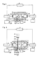
- Fig. 2 ist eine Darstellung der photothermischen Gasdetektionsvorrichtung mit Modulations- und Filtiermitteln für die einfallende Lichtstrahlung.
- Fig. 3 zeigt eine Darstellung des Gaskalorimeters, das auf einem Ultraschallresonator beruht und für ein fluidförmiges Messgut geeignet ist.
- Fig. 4 veranschaulicht ein entsprechendes Gaskalorimeter für festes oder flüssiges Messgut.
- Fig. 5 zeigt eine Darstellung eines Kalorimeters zur Untersuchung von Lichtleitern und integriert-optischen Elementen.
- 1 shows an overview of an ultrasonic resonator device for measuring temperature fluctuations which are caused by light absorption in a gas.
- Fig. 2 is an illustration of the photothermal gas detection device with modulating and filtering means for the incident light radiation.
- FIG. 3 shows a representation of the gas calorimeter, which is based on an ultrasound resonator and is suitable for a fluid measuring material.
- 4 illustrates a corresponding gas calorimeter for solid or liquid material to be measured.
- 5 shows a representation of a calorimeter for examining light guides and integrated optical elements.
Die Darstellung von Fig.1 zeigt den Aufbau der bereits erwähnten Ultraschall-Vorrichtung zum Messen von kleinen, durch Absorption von Infrarotstrahlung bedingten Temperaturschwankungen in einem Gas. Die Methode der Gastemperaturmessung beruht auf der grossen Temperaturabhängigkeit der Schallgeschwindigkeit von Gasen. Dieselbe wird mittels eines Ultraschallfeldes, vornehmlich in Form eines akustischen Resonators 1, gemessen. Die akustische Resonanz baut sich zwischen dem Ultraschallwandler-Paar, bestehend aus dem Ultraschall-Sender 2 und dem Ultraschall-Empfänger 3, auf.The illustration in FIG. 1 shows the structure of the already mentioned ultrasonic device for measuring small temperature fluctuations in a gas caused by absorption of infrared radiation. The gas temperature measurement method is based on the large temperature dependence of the speed of sound of gases. The same is measured by means of an ultrasound field, primarily in the form of an
Der Ultraschall-Sender 2 wird durch den Generator 4 bei einer Frequenz von typischerweise mehreren hundert kHz angeregt. Das Signal des Generators kann sinusförmig sein oder aus einer regelmässigen Folge von beispielsweise rechteckförmigen Pulsen bestehen. Am Empfänger 3 erscheint ein Signal, dessen Enveloppe (peak-to-peak-Wert), nebst von der Empfindlichkeit des Empfängers 3 und der Schallabsorption im Resonatorraum 1, von der Abstimmung des Resonators 1 abhängt. Das Empfängersignal wird einer Vorrichtung 5 - im folgenden als Analysator bezeichnet - zugeführt. Diese Vorrichtung 5 analysiert entweder die Enveloppe des empfangenen Signals oder sie bestimmt die Phasenlage des Signals bezüglich des Eingangssignals am Sender 2. Diese Analyse des vom Empfänger 3 gelieferten Signals beruht beispielsweise auf einer peak-to-peak-Messung, einer Gleichrichtung mit nachfolgenden Glättung, einer Phasendetektion oder einer phasenempfindlichen Verstärkung mittels eines Lock-in-Verstärkers.The
Es ist angezeigt, den Ultraschallresonator durch Wahl der Frequenz und der Länge des Resonators im Fall einer Enveloppenanalyse in einer Resonanzflanke zu betreiben. Bei der Phasendetektion wird der Resonator vorteilhafterweise im Resonanzmaximum, also im Bereich der grössten Phasenänderung, betrieben. Weiterhin ist die Wahl einer möglichst hohen Ultraschall-Frequenz wegen der weitgehenden Proportionalität der Enveloppen-Steigung zur Frequenz empfehlenswert.It is advisable to operate the ultrasound resonator in a resonance flank by selecting the frequency and the length of the resonator in the case of an envelope analysis. In phase detection, the resonator is advantageously operated at the resonance maximum, ie in the area of the greatest phase change. Furthermore, the choice of the highest possible ultrasound frequency is recommended due to the fact that the envelope slope is largely proportional to the frequency.
Die obere Limite der Ultraschall-Frequenz ist durch das Schallabsorbtionsvermögen des Probegases, das oberhalb von 100 kHz mit zunehmender Frequenz stark ansteigt, gegeben. Es ist allerdings fest-zuhalten, dass die Frequenz höher gewählt werden kann, als dies mit kommerziellen luft-angepassten Ultraschallwandlern möglich ist (50 kHz bis 220 kHz). Im vorliegenden Fall muss nämlich das Schallsignal nicht über eine Distanz von mehreren Metern oder Dezimetern effizient übertragen werden, wie das normalerweise erwünscht ist, sondern lediglich über einen Abstand im Millimeter-Bereich.The upper limit of the ultrasound frequency is given by the sound absorption capacity of the sample gas, which rises sharply above 100 kHz with increasing frequency. However, it should be noted that the frequency can be selected higher than is possible with commercial air-adapted ultrasonic transducers (50 kHz to 220 kHz). In the present case, the sound signal does not have to be transmitted efficiently over a distance of several meters or decimeters, as is normally desired, but only over a distance in the millimeter range.
Mit dem Betrieb des Ultraschallresonators in einer Resonanzflanke bei der Enveloppenanalyse, oder im Resonanzmaximum bei der Phasendetektion sowie der Wahl einer hohen Frequenz wird erreicht, dass sich eine - beispielsweise temperaturbedingte - Aenderung in der Abstimmung maximal auf das Ausgangssignal des Analysators 5 auswirkt.With the operation of the ultrasonic resonator in a resonance flank in the envelope analysis, or in the resonance maximum in phase detection and the selection of a high frequency, it is achieved that a change in the tuning, for example temperature-related, has a maximum effect on the output signal of the
Die Aenderung der Resonator-Abstimmung lässt sich nun direkt der Veränderung der Signal-Enveloppe, also dem Quasi-Gleichstrom-Wert resp. der Phasenverschiebung am Analysator 5 entnehmen. Es ist allerdings festzuhalten, dass in beiden Fällen der lineare Temperatur-Messbereich sehr beschränkt ist. Da aber nur kleine Temperaturschwankungen gemessen werden sollen, ist diese Einschränkung nicht gravierend. Allerdings können langsame driftartige Temperaturänderungen ein Abwandern der Resonaturabstimmung und somit eine Aenderung der Temperaturempfindlichkeit bewirken. Es muss daher nach Wegen gesucht werden, grossen Langzeiteffekten wirkungsvoll entgegenzuwirken.The change in the resonator tuning can now be directly related to the change in the signal envelope, i.e. the quasi-direct current value or the phase shift on the
Beispielsweise kann die Ultraschallfrequenz derart nachgeführt werden, dass die Resonator-Abstimmung, das heisst der peak-to-peak-Wert am Empfänger 3, konstant bleibt. Zu diesem Zweck kann beispielsweise das Ausgangssignal des Analysators 5 als Steuer-Signal über einen geeigneten Regler 6 einem spannungsgesteuerten Generator 4 zugeführt werden.For example, the ultrasound frequency can be tracked in such a way that the resonator tuning, that is to say the peak-to-peak value at the
Der überstreichbare Temperatur-Messbereich ist durch den Operationsbereich der Ultraschallwandler gegeben. Typischerweise lassen sich mit Ultraschall-Wandlern 2, 3 Frequenzbereiche von 1% bis 2% der Sollfrequenz überstreichen.The temperature measurement range that can be covered is given by the operating range of the ultrasonic transducers. Typically, ultrasonic transducers can sweep 2, 3 frequency ranges from 1% to 2% of the target frequency.
Ein beliebig grosser Temperaturbereich lässt sich hingegen erreichen, wenn der Resonator 1 nicht elektrisch, sondern mittels eines Reglers 16 und einer mechanischen Verschiebe-Vorrichtung 12 durch Veränderung des Ultraschall-Wandler-Abstandes abgestimmt wird. Es ist allerdings festzuhalten, dass in diesem Falle die Abstimmung verhältnismässig aufwendig ist. Insbesondere sind die Präzisions-Anforderung an den mechanischen Aufbau beachtlich. Beispielsweise fällt die Kreisgüte des Ultraschallresonators 1 stark ab, wenn die Oberflächen der Ultraschall-Wandler 2, 3 nicht genau parallel justiert sind.On the other hand, an arbitrarily large temperature range can be achieved if the
Denkbar ist auch eine Kombination beider Abstimmungsarten des Ultraschall-Resonators, also der mechanischen und der elektrischen Abstimmung. In Fig. 1 ist diese Situation eingezeichnet. Beispielsweise kann die Grobabstimmung mechanisch mit Hilfe des entsprechenden Reglers 16 und der Verschiebe-Vorrichtung 12 vorgenommen werden, während die Feinabstimmung elektrisch mittels des Reglers 6 und des spannungskontrollierten Oszillators 4 bewerkstelligt wird.A combination of both types of tuning of the ultrasonic resonator, that is mechanical and electrical tuning, is also conceivable. This situation is shown in FIG. 1. For example, the rough adjustment can be carried out mechanically with the aid of the corresponding
Aus dem Ausgangs-Signal des Analysators 5, resp. aus der Regelgrösse, kann auf die Schallgeschwindigkeit und damit auf die Temperatur des Gases im Ultraschallresonator 1 geschlossen werden. Das Ausgangssignal des Analysators 5 wird daher in einem Registriergerät 8 festgehalten.From the output signal of the
Temperatur-Variationen im Ultraschallresonator 1 können beispielsweise durch Licht- 17, insbesondere Infrarot-Einstrahlung, erreicht werden. Kleine Temperatur-Schwankungen im Ultraschallresonator 1, welche durch Absorption von intensitäts-modulierter Lichtstrahlung bewirkt werden und demzufolge mit dem Lichtsignal korreliert sind, sind beispielsweise mittels eines Analysators 15 in Form eines Lock-in-Verstärkers messbar. Letzterer verwendet als Referenz das intensitätsmodulierte Signal der Lichtquelle 7. Das Ausgangssignal des Analysators 15 ist der gesuchte Messwert, der über die Lichtabsorption im Ultraschallresonator Auskunft gibt. Dieses Signal wird daher einem Registriergerät 8, beispielsweise in Form eines Schreibers, eines Voltmeters oder eines Rechnereinganges, zugeführt. Das beschriebene Verfahren erlaubt es, Gastemperatur-Aenderungen bis in den Bereich von 10 Grad zu messen. Genauere Angaben sind in den vorgängig erwähnten Artikeln von O. Oehler, J. Wieland und S.Friedrich festgehalten.Temperature variations in the
Es scheint zunächst wenig sinnvoll, einerseits das Ausgangssignal des Analysators 5 zur weiteren Analyse im Lock-in-Verstärker 15 zu verwenden, andererseits dieses Signal beispielsweise mittels des Reglers 6 auf festem Wert zu halten. Es ist aber naheliegend, mit Hilfe des Reglers 6 langsame Drifterscheinungen zu kompensieren, sodass dem Lockin-Verstärker 15 die Messung der raschen, mit der Lichtquelle synchronen Signale zukommt.At first it does not seem to make much sense to use the output signal of the
Fig. 2 zeigt eine detaillierte Darstellung einer Vorrichtung zur Messung des photothermischen Effektes. Der Ultraschallresonators 1 wird durch die beiden Ultraschallwandler 2, 3, die einander gegenüber angeordnet sind, gebildet. Das Licht der Quelle 7 gelangt durch ein Fenster 11 in den als Gasküvette ausgebildeten Ultraschallresonator 1. Zum Austausch des gasförmigen Messgutes 20 ist mindestens eine Oeffnung 22, 22′ in der Wandung der Gasküvette vorhanden. Gegebenenfalls sind die Oeffnungen mit Strömungswiderständen 23, 23′ versehen. Diese Strömungswiderstände können Ventile, Rohrverengungen 23 oder Filterplatten 23′, resp. gaspermeable Membranen sein. Es ist festzuhalten, dass diesen Strömungswiderständen 23, 23′ keine akustisch dämmende Wirkung zukommen muss - im Gegensatz zu photoakustischen Messungen bei tiefer Frequenz, wo eine gute akustische Abtrennung der Zelle von der Aussenwelt unumgänglich ist. Es muss lediglich erreicht werden, wie bereits erwähnt worden ist, dass sich äussere Temperaturfluktuationen nicht auf den Ultraschallresonator 1 auswirken können. Auf das Lichteintrittsfenster 11 könnte verzichtet werden, falls gewährleistet ist, dass die Oeffnung im Ultraschallresonator keine wesentlichen gaszirkulations-bedingten Temperaturfluktuationen bewirkt.2 shows a detailed illustration of a device for measuring the photothermal effect. The
Zur Verhinderung von unerwünschten Temperaturfluktuationen im Ultraschallresonator 1 ist es empfehlenswert, denselben mit einer mantelförmigen Wärmeisolation 27 zu umgeben und/oder gegebenenfalls mittels einer Heizung 28, einem Heizungssteuergerät 28′ und einem Thermosensors 28˝ auf konstanter Temperatur zu halten. Ebenso kann es Vorteile bringen, das gasförmige Messgut durch Beheizung der Zuleitungen mittels der Heizelemente 38, 38′ auf die Temperatur des Ultraschallresonators zu bringen.To prevent undesirable temperature fluctuations in the
Die Lichtquelle 7 ist intensitätsmoduliert, was beispielsweise durch Ein- und Aus-Schalten des Stromes, oder mittels eines Lichtchoppers 18, der sich im Lichtstrahl 17 zwischen der Lichtquelle 7 und dem Ultraschallresonator 1 befindet, erreicht wird. Zusätzlich kann im Lichtstrahl 17 ein optisches Filter 11′ angeordnet sein.The light source 7 is intensity-modulated, which is achieved, for example, by switching the current on and off, or by means of a
Die Einfügung eines solchen Filters ist vor allem dann angezeigt, wenn die Quelle 7 ein breitbandiges Spektrum aufweist, also wenn beispielsweise die Lichtquelle 7 ein thermischer Strahler ist. In diesem Falle kann ein optisches Bandpass-Filter 11′ hinreichend monochromatische Strahlung erzeugen, sodass eine selektive Lichtabsorption durch Gase in der Küvette gewährleistet ist.The insertion of such a filter is particularly indicated if the source 7 has a broadband spectrum, that is to say if, for example, the light source 7 is a thermal radiator. In this case, an optical bandpass filter 11 'can generate sufficient monochromatic radiation, so that selective light absorption by gases in the cuvette is ensured.
Falls die Wellenlänge des im Ultraschallresonator 1 durch das Fenster 11 einfallende Licht in einen spektralen Bereich fällt, wo Gase selektiv absorbieren, kann die in Fig.1 und Fig. 2 dargestellte Vorrichtung zum selektiven Nachweis von Gasen verwendet werden. Die Empfindlichkeit ist zwar nicht derart hoch, wie bei einer auf dem photoakustischen Effekt basierenden Vorrichtung, hingegen weist die besprochene Vorrichtung eine praktisch verschwindende Störanfälligkeit gegenüber Druckfluktuationen und Körperschall auf.If the wavelength of the light incident in the
In Fig. 3 ist eine Ausführungsform eines auf einem Ultraschallresonator 1 beruhenden Kalorimeters dargestellt. In Analogie zu der in Fig. 1 gezeigten Vorrichtung, wird die lokale Temperatur eines Gases gemessen. Dasselbe kann die Messprobe selbst sein, oder eine fluidförmige Messprobe umgeben. Im Unterschied zur Vorrichtung von Fig. 1 führt aber nicht die Absorption von Licht zu einer Aenderung der Gastemperatur, sondern das thermische Verhalten des Messgutes, beispielsweise eine chemische Reaktion in einem Gas, einem Aerosol, oder einer Flüssigkeit, das in den Ultraschallresonator 1 gebracht worden ist. Die Kalorimeter-Vorrichtung 30 besteht wiederum aus den beiden Ultraschallwandlern 2, 3, welche, den Ultraschallresonator 1 seitlich begrenzend, einander gegenüber angeordnet sind.FIG. 3 shows an embodiment of a calorimeter based on an
Der als Sender 2 eingesetzte Ultraschallwandler steht mit einem Oszillator 4 in Verbindung und wird von demselben angeregt. Der empfangende Ultraschallwandler 3 gibt sein Ausgangssignal an den Analysator 5 ab, wo dasselbe aufgrund einer Enveloppen- oder Phasen-Analyse ausgewertet wird. Die Abstimmung des Oszillators 4 wird beispielsweise mittels des Reglers 6 nachgestellt. In Bezug auf die Funktionsweise des Temperatrmessverfahrens sei auf die Beschreibung von Fig. 1 hingewiesen.The ultrasonic transducer used as
Für die Genauigkeit dieser Messmethode ist es wesentlich, dass die lokale Temperaturverteilung in der Umgebung des Messgutes 24 nicht durch äussere Einflüsse gestört wird. Das kann einerseits dadurch erreicht werden, dass der Kalorimeterraum weitgehend abgeschlossen ist und damit nicht unter dem Einfluss äusserer Luftströmungen steht. Andererseits ist dafür zu sorgen, dass die Innenwandungen des Kalorimeters eine möglicht konstante und gleichmässige Temperatur aufweisen. Damit können unerwünschte Konvektionsströmungen innerhalb des Kalorimeters verhindert werden. Zu diesem Zweck ist es empfehlenswert, den Ultraschallresonator 1 sowie die Ultraschallwandler 2, 3 mit einer mantelförmigen Wärmeisolation 27 zu umgeben.For the accuracy of this measurement method, it is essential that the local temperature distribution in the vicinity of the material to be measured 24 is not disturbed by external influences. This can be achieved on the one hand by the fact that the calorimeter room is largely closed and is therefore not influenced by external air currents. On the other hand, it must be ensured that the inside walls of the calorimeter have a temperature that is as constant and uniform as possible. This can prevent unwanted convection currents within the calorimeter. For this purpose, it is advisable to surround the
Weiter ist es angezeigt, den Ultraschallresonator 1 mit einer thermostatisierten Heizung 28 zu versehen. In Analogie zur Vorrichtung von Fig. 2 regelt dieselbe, 28, mittels des Heizungssteuergeräts 28′ und des Thermosensors 28˝ die Temperatur des Ultraschallresonators 1.It is also indicated to provide the
Der Ultraschallsender 2 stellt eine massgebende Wärmequelle dar. Um stationäre thermische Verhältnisse zu schaffen ist es daher angebracht, die Ultraschallwandler 2, 3, insbesondere den Sender 2, mit Kühlungen 36, 36′, beispielsweise in Form von Kühlrippen oder Peltier-Elementen, zu versehen.The
Da die Impedanz der Ultraschallwandler 2, 3 leicht von der Betriebsfrequenz abhängt - bei Resonanz tritt ein Impedanz-Minimum auf - ist auch die thermische Belastung der Ultraschallwandler 2, 3 bei Veränderung der Betriebsfrequenz leicht variabel. Um eine gleichmässige Temperatur der Ultraschallwandler zu gewährleisten, ist es daher vorteilhaft, die Wandler mittels der Heizelemente 37, 37′ derart zu beheizen, dass die Wärmezufuhr an den Ultraschallwandlern 2, 3 konstant ist. In Analogie zu der Heizung 28 des Ultraschallresonators 1 kann das mittels eines Heizungssteuergerätes und Thermosensoren geschehen.Since the impedance of the
Das zu untersuchende gasförmige oder flüssige Fluid wird beispielsweise über Ventile 32, 32′ und die Zuleitungen 33, 33′ in das Reaktionsgebiet 31 des Ultraschallresonators 1 eingegeben. Um eine Wärmezufuhr über das Fluid zu verhindern, wird dasselbe gegebenenfalls, beispielsweise mittels der Heizelemente 38, 38′, die an den Zuleitungen 33, 33′ befestigt sind, vorgängig auf die Temperatur, die im Innern des Ultraschallresonators 1 herrscht, gebracht.The gaseous or liquid fluid to be examined is entered, for example, via
Es wurde vorgängig bereits darauf hingewiesen, dass die Eichung des Kalorimeters sehr wichtig ist, da die Temperatur des Messgutes 20 nicht direkt bestimmt wird. Dazu dient beispielsweise ein Heizelement 34, das über ein Speisegerät 34′ betrieben wird.It was previously pointed out that the calibration of the calorimeter is very important since the temperature of the measured
Es ist festzuhalten, dass kalorimetrische Untersuchung von Gasen und Aerosolen mittels der beschriebenen Vorrichtung eine Ausnahme darstellen dürfte, da die Schallgeschwindigkeit nicht nur von der Gastemperatur, sondern auch wesentlich von der Gasart abhängig ist. Es wird daher nicht nur die Wärmetönung der Gasreaktion, sondern auch die Gaszusammensetzung im Reaktorraum gemessen.It should be noted that calorimetric analysis of gases and aerosols using the described device should be an exception, since the speed of sound is not only dependent on the gas temperature, but also essentially on the type of gas. It is therefore not only the heat of the gas reaction that is measured, but also the gas composition in the reactor space.
Fig. 4 zeigt eine Kalorimeter-Vorrichtung, die für Untersuchungen an Festkörpern und Flüssigkeiten geeignet ist. Die Vorrichtung hat damit einen ähnlichen Einsatzbereich, wie das erwähnte Differential Scanning Kalorimeter. Im Gegensatz aber zu jenem wird nicht die Temperatur des Messgutes 1 direkt bestimmt, sondern vielmehr diejenige des umgebenden Gases.Fig. 4 shows a calorimeter device which is suitable for investigations on solids and liquids. The device thus has a similar area of use as the differential scanning calorimeter mentioned. In contrast to this, however, it is not the temperature of the measured
Der Aufbau der Vorrichtung ist sehr ähnlich wie derjenige, der im Zusammenhang mit Fig. 3 beschrieben worden ist. Im Gegensatz aber zur vorangehenden Beschreibung wird das Messgut nicht direkt über Zuleitungen 33, 33′ in den Ultraschallresonator eingeleitet, sondern ist mechanisch im Ultraschallresonator 1 fixiert. Gegenüber dem Differential-Kalorimeter muss aber das feste Messgut 40 nicht in einen Tiegel 43 gegeben werden, sondern kann direkt, beispielsweise durch dünne Halterungen 41, 41′, im Ultraschallresonator befestigt sein. Diese Halterungen können beispielsweise elektrische Zuleitungen sein, welche die Reaktion im Messgut 40 auslösen.The construction of the device is very similar to that which has been described in connection with FIG. 3. In contrast to the preceding description, however, the material to be measured is not introduced directly into the ultrasound resonator via
Flüssigkeiten können beispielsweise über dünne kapillaren, die gleichzeitig die Funktion der Halterungen 41, 41′ übernehmen, in den Ultraschallresonator 1 eingebracht werden. Das flüssige Messgut kann entweder an den Kapillarspitzen vorhanden sein, oder sich in einem kleinen Tiegel 43 befinden.Liquids can, for example, be introduced into the
Die übrigen Kalorimeterkomponenten, wie das Referenz-Heizelement 34, die Heizungen 28, 37, 37′ des Ultraschallresonators 1, resp. der Ultraschallwandler 2, 3, die Kühlungen 36, 36′ der Ultraschallwandler und der thermisch isolierende Mantel 27 des Kalorimeters, wurden bereits vorgängig beschrieben.The other calorimeter components, such as the
Fig. 5 zeigt eine Darstellung eines Kalorimeters zur Untersuchung von optischen Komponenten. An sich besteht ein grosses Interesse für kalorimetrische Messungen an integriert-optischen und optoelektronischen Komponenten, wie lichtleitenden Fasern, integriert-optischen Lichtemittern, Lichtempfängern, opto-elektronischen Lichtschaltern und Verbindungsstellen zwischen optischen Komponenten. Nur anhand thermischer Untersuchungen ist es möglich, die im optischen Material aufgetretene Lichtabsorption von ungewollter Lichtstreuung und Lichtauskopplung zu unterscheiden. Die absorbierte Lichtleistung wird in kalorimetrisch messbare Wärme umgesetzt, während das ungewollt ausgekoppelte Licht kalorimetrisch nicht in Erscheinung tritt. Eine Optimierung der optischen Komponenten erfordert eine genaue Kenntnis der Herkunft der Verluste. Aus diesem Grunde wurden verschiedentlich die optischen Verluste in optischen Materialien und Komponenten, wie etwa Glasfasern, kalorimetrisch gemessen. Beispielsweise wurde, wie bereits erwähnt, der optische Verlust in Glas dadurch bestimmt, dass ein Glasstab in den optischen Resonator eines leistungsstarken Lasers gebracht und die Probentemperaturerhöhung während des Laserbetriebes, sowie die Zeitkonstante der Temperaturerniedrigung nach Ausschalten des Lasers, gemessen wurden (T.C.Rich and D.A. Pinnow, Appl. Phys. Lett. 20, 264 (1972). Weiter wurde, wie ebenfalls bereits erwähnt, die optische Absorption von Thallium-Halogeniden photoakustisch bestimmt, indem das Messgut in einen verschlossenen Raum gebracht und die durch Lichtabsorption bedingten Druckänderungen mittels eines Mikrophons gemessen wurden (P. Horn, A.Schmid and P.Bräunlich, Jour. Quantum Electr., QE 19, 1169 (1983)).5 shows a representation of a calorimeter for examining optical components. As such, there is great interest in calorimetric measurements on integrated optical and optoelectronic components, such as light-guiding fibers, integrated optical light emitters, light receivers, optoelectronic light switches and connection points between optical components. It is only possible to distinguish the light absorption that occurs in the optical material from unwanted light scattering and light decoupling using thermal tests. The absorbed light output is converted into calorimetrically measurable heat, while the unwanted outcoupled light does not appear calorimetrically. Optimizing the optical components requires precise knowledge of the origin of the losses. For this reason, the optical losses in optical materials and components, such as glass fibers, have been calorimetrically measured in various ways. For example, as already mentioned, the optical loss in glass was determined by placing a glass rod in the optical resonator of a powerful laser and measuring the sample temperature increase during laser operation and the time constant of the temperature decrease after switching off the laser (TCRich and DA Pinnow , Appl. Phys. Lett. 20 , 264 (1972). As already mentioned, the optical absorption of thallium halides was further determined photoacoustically by placing the measured material in a closed space and measuring the pressure changes caused by light absorption using a microphone (P. Horn, A. Schmid and P. Braunlich, Jour. Quantum Electr., QE 19 , 1169 (1983)).
Wie bereits erwähnt, können kalorimetrische Messungen an optischen Komponenten unter Betrieb nicht im Wasser vorgenommen werden. Die wässrige Umgebung würde die Lichtführung, bedingt durch den Brechungsindex des Wassers, wesentlich verändern oder gar verunmöglichen. Es ist daher notwendig, die Messungen in einem Gaskalorimeter vorzunehmen. Bei Verwendung eines herkömmlichen Differential-Kalorimeters ergeben sich bei der Lösung des Problems der Lichteinkopplung und der Schaffung eines guten thermischen Kontaktes zwischen Probe und Festkörper-Temperatursensor grosse technische Schwierigkeiten. An sich könnten Thermoelemente beispielsweise durch Aufdampfen auf dem Messgut angebracht werden, doch wäre der Aufwand beträchtlich.As already mentioned, calorimetric measurements on optical components cannot be carried out in water during operation. The watery environment would be caused by the lighting Refractive index of water, change significantly or even make it impossible. It is therefore necessary to carry out the measurements in a gas calorimeter. When using a conventional differential calorimeter, there are great technical difficulties in solving the problem of light coupling and in creating good thermal contact between the sample and the solid-state temperature sensor. Thermocouples could be attached to the material to be measured, for example by vapor deposition, but the effort would be considerable.
In der Vorrichtung nach Fig. 5 wird die Einkopplung des Lichtstrahles 51 in das optisch leitende Messgut 50 ausserhalb des Kalorimeterraumes 1 mittels der fokussierenden Optik 52 im Einkopplungsbereich 53 vorgenommen. Das auf der gegenüberliegenden Seite des Ultraschallresonators 1 im Bereich 54 aus dem optischen Element 50 ausgekoppelte Licht wird gegebenenfalls nach einer weiteren Fokussierung mittels der Optik 52′ einem Lichtdetektor 55 zugeführt. Anhand des Signales an diesem Lichtdetektor 55 lässt sich der optische Verlust bestimmen.In the device according to FIG. 5, the
Die übrigen Komponenten des Kalorimeters wurden im Zusammenhang mit den Fig. 3, 4, und 5 eingehend beschrieben, sodass darauf nicht mehr eingegangen werden muss.The other components of the calorimeter have been described in detail in connection with FIGS. 3, 4 and 5, so that they no longer need to be discussed.
Die kalorimetrische Messung wird entweder vorgenommen, indem die Gastemperatur in den Umgebung des optisch leitenden Elementes 50 vor und nach Einschalten der optischen Lichteinkopplung gemessen wird, oder indem das Licht alternierend bei sehr tiefer Frequenz in das Messgut 50 eingekoppelt wird.The calorimetric measurement is carried out either by measuring the gas temperature in the vicinity of the optically
Bis anhin wurde vorausgesetzt, dass sich Luft im Kalorimeterraum befindet. Es ist aber auch denkbar, dass ein anderes Gas verwendet wird. Insbesondere brächte ein Gas mit guter Wärmeleitfähigkeit, wie etwa Wasserstoff oder Helium, den Vorteil einer kleinen Abkühl-Zeitkonstanten. Damit könnte beispielsweise die Modulationsfrequenz im alternierenden Betrieb des Kalorimeters erhöht werden.Until now, it was assumed that there was air in the calorimeter room. However, it is also conceivable that a different gas is used. In particular, a gas with good thermal conductivity, such as hydrogen or helium, would have the advantage of a small cooling time constant. This could, for example, increase the modulation frequency in alternate operation of the calorimeter.
Claims (28)
- Process for the thermal investigation of a measuring material in a gaseous environment, characterized in that- the measuring material is placed in the gaseous cavity of an ultrasonic resonator,- the ultrasonic resonator is composed of two facing ultrasonic transducers, one being operated as a transmitter and the other as a receiver, and- the heat given off by the measuring material to the gaseous environment or absorbed by the measuring material from the gaseous environment is measured via the temperature-dependent change of the tuning of the ultrasonic resonator.
- Process according to claim 1, characterized in that the change of the tuning of the ultrasonic resonator is measured on the basis of the amplitude change of the ultrasonic resonator operated in one flank of a resonance or on the basis of the phase change between emitted and received ultrasonic signals in the ultrasonic resonator operated close to resonance.
- Process according to claim 2, characterized in that regulating means are provided for controlling the tuning of the ultrasonic resonator.
- Process according to claim 2, characterized in that intensity-modulated and optionally monochromatic light is irradiated onto the measuring material inside of the ultrasonic resonator.
- Process according to claim 4, characterized in that means are provided which permit the exchange of the gaseous measuring material.
- Process according to claim 5, characterized in that the measuring material is gaseous and a photothermal gas analysis is performed by radiating light into the ultrasonic resonator.
- Process according to one of the claims 1 to 3, characterized in that the measuring material is calorimetrically investigated.
- Process according to claim 7, characterized in that an additional heat source is used in the ultrasonic resonator as a heat reference.
- Process according to one of the claims 7 or 8, characterized in that the measuring material is a gaseous or liquid fluid or a fluid mixture and the fluid or its components are brought by means of at least one feed line into the ultrasonic resonator before or during the calorimetric measurement.
- Process according to one of the claims 7 or 8, characterized in that the measuring material is a solid and is fixed in the ultrasonic resonator.
- Process according to claim 7, characterized in that during the calorimetric investigation, the measuring material is continuously or alternately supplied with energy from the outside.
- Process according to claim 11, characterized in that the measuring material is a light-conducting element and can be supplied with energy in the form of light.
- Process according to claim 11, characterized in that the measuring material has a non-disappearing electrical conductivity and can be supplied with electrical energy.
- Apparatus for the thermal investigation of a measuring material (20, 50) in a gaseous environment, comprising a separate chamber, the so-called calorimeter chamber (21), and temperature measuring means for determining the heat given off by the measuring material (20, 50) to the surrounding gas, or absorbed by the measuring material from the surrounding gas, whereby- the temperature measuring means are two facing ultrasonic transducers (2, 3) located on the edge of the calorimeter chamber (21), and- one of them (2) being operated as a transmitter is connected to an oscillator (4), whilst the other (3), is operated as a receiver and connected to an analyser (5),
characterized in that- the ultrasonic transducers (2, 3) are spaced in such a way that they form an acoustic resonator, and- there are means (6, 12, 16) for measuring the tuning of the ultrasonic resonator. - Apparatus according to claim 14, characterized in that the ultrasonic receiver (3) is connected to an analyser (5), which records the amplitude change of the ultrasonic signal or the phase change with respect to the signal applied to the ultrasonic transmitter (2) in order to measure the tuning of the ultrasonic resonator (1).
- Apparatus according to claims 14 or 15, characterized in that the analyser (5) is connected via a first regulator (6) to the oscillator (4) and/or via a second regulator (16) to the mechanical shifting device (12) for shifting one of the two ultrasonic transducers (2,3).
- Apparatus according to one of the claims 14 to 16, characterized in that the calorimeter chamber (21) is provided with an optionally window-covered (11) opening and means (22, 22′, 23, 23′) are provided for gas exchange purposes.
- Apparatus according to claim 17, characterized in that a switching device is provided for switching on and off the current for a light source (7), or a light chopper (18) is located in the light-beam (17) between the light source (7) and the ultrasonic resonator (1) and/or an optical filter (11′) is located in the light beam (17).
- Apparatus according to claim 18, characterized in that there is at least one opening (22, 22′) in the wall of the calorimeter chamber (21) and said openings are optionally provided with flow resistances (23, 23′) in the form of valves, pipe constrictions (23) or filter plates (23′).
- Apparatus according to one of the claims 14 to 16, characterized in that means (34, 34′, 41, 41′, 52, 52′) are provided, which make it possible to couple energy into or out of the resonator chamber (21).
- Apparatus according to claim 20, characterized in that the calorimeter chamber (21) between the ultrasonic transducers (2, 3) additionally contains a reference heating element (34), which is connected to a feed device (34′).
- Apparatus according to one of the claims 20 or 21, characterized in that there is at least one feed line (33, 33′), which is able to introduce into the calorimeter chamber (21) the measuring material in the form of a gaseous or liquid fluid or components thereof.
- Apparatus according to one of the claims 20 or 21, characterized in that at least one holding support (41,41′) is provided for fixing the measuring material in the form of a solid or an enclosed liquid in the calorimeter chamber (21).
- Apparatus according to claim 23, characterized in that there is at least one focussing optics (52,52′) making it possible to couple in and optionally out light into the measuring material in the form of a light-conducting element (50).
- Apparatus according to claims 14 to 24, characterized in that means are provided, which comprise a heating element (28), a heating control device (28′) and a temperature sensor (28˝), which make it possible to keep the edges of the calorimeter container at a constant temperature, or to change said temperature in a prescribed way.
- Apparatus according to claims 14 to 24, characterized in that means are provided, which comprise the heating elements (37, 37′), a heating control device and temperature sensors and optionally cooling means (36, 36′), which make it possible to keep at least one of the ultrasonic transducers (2, 3) at a constant temperature, or to change its temperature in a prescribed way.
- Use of the apparatus according to one of the claims 14 to 19 for the selective detection of gases.
- Use of the apparatus according to one of the claims 14 to 19 for the calorimetric investigation of light guides.
Priority Applications (1)
| Application Number | Priority Date | Filing Date | Title |
|---|---|---|---|
| AT89902017T ATE83316T1 (en) | 1988-02-19 | 1989-02-17 | ULTRASONIC TEMPERATURE MEASUREMENT AND APPLICATIONS IN OPTICAL SPECTROSCOPY AND CALORIMETRY. |
Applications Claiming Priority (4)
| Application Number | Priority Date | Filing Date | Title |
|---|---|---|---|
| CH624/88 | 1988-02-19 | ||
| CH62488 | 1988-02-19 | ||
| CH491/89 | 1989-02-13 | ||
| CH49189 | 1989-02-13 |
Publications (2)
| Publication Number | Publication Date |
|---|---|
| EP0362307A1 EP0362307A1 (en) | 1990-04-11 |
| EP0362307B1 true EP0362307B1 (en) | 1992-12-09 |
Family
ID=25684727
Family Applications (1)
| Application Number | Title | Priority Date | Filing Date |
|---|---|---|---|
| EP89902017A Expired - Lifetime EP0362307B1 (en) | 1988-02-19 | 1989-02-17 | Ultrasonic temperature measurement and applications in optical spectroscopy and calorimetry |
Country Status (3)
| Country | Link |
|---|---|
| US (1) | US5141331A (en) |
| EP (1) | EP0362307B1 (en) |
| WO (1) | WO1989007753A1 (en) |
Families Citing this family (46)
| Publication number | Priority date | Publication date | Assignee | Title |
|---|---|---|---|---|
| GB8923699D0 (en) * | 1989-10-20 | 1989-12-06 | Univ Strathclyde | Apparatus for assessing a particular property in a medium |
| US5296374A (en) * | 1989-10-20 | 1994-03-22 | University Of Strathclyde | Apparatus for assessing a particular property in a medium |
| EP0456787B1 (en) * | 1989-12-08 | 1994-07-27 | OEHLER, Oscar, Dr. | Selective gas detection by field separation and sound velocity measurement: detection of oxygen |
| JP3224286B2 (en) * | 1992-11-02 | 2001-10-29 | 株式会社日本自動車部品総合研究所 | Temperature measurement device using ultrasonic waves |
| US5581295A (en) * | 1992-11-27 | 1996-12-03 | Eastman Kodak Company | Method and apparatus for resequencing image data for a printhead |
| DE4309250A1 (en) * | 1993-03-23 | 1994-09-29 | Grau Gmbh & Co Holdingges | Disk archive system |
| DE4313216C2 (en) * | 1993-04-22 | 1995-12-14 | Max Planck Gesellschaft | Ultrasonic measuring device with at least one non-piezoelectric resonator chamber body and externally arranged electro-acoustic transducers |
| US5549387A (en) * | 1994-06-01 | 1996-08-27 | The Perkin-Elmer Corporation | Apparatus and method for differential analysis using real and imaginary signal components |
| ES2221925T3 (en) * | 1995-09-04 | 2005-01-16 | Siemens Building Technologies Ag | PHOTOACUSTIC GAS SENSOR AND ITS USE. |
| US5840023A (en) * | 1996-01-31 | 1998-11-24 | Oraevsky; Alexander A. | Optoacoustic imaging for medical diagnosis |
| US6405069B1 (en) | 1996-01-31 | 2002-06-11 | Board Of Regents, The University Of Texas System | Time-resolved optoacoustic method and system for noninvasive monitoring of glucose |
| US6309352B1 (en) | 1996-01-31 | 2001-10-30 | Board Of Regents, The University Of Texas System | Real time optoacoustic monitoring of changes in tissue properties |
| US5772322A (en) * | 1996-05-31 | 1998-06-30 | Honeywell Inc. | Resonant microbeam temperature sensor |
| EP0846261A1 (en) * | 1996-06-22 | 1998-06-10 | Oscar Oehler | Tuning and calibrating a photothermal gas detector |
| US5768937A (en) * | 1996-11-13 | 1998-06-23 | Leybold Inficon, Inc. | Acoustic sensor for in-line continuous monitoring of gasses |
| US5894352A (en) * | 1997-05-20 | 1999-04-13 | Cymer, Inc. | Absorption tester for optical components |
| US5852308A (en) * | 1997-06-30 | 1998-12-22 | Honeywell Inc. | Micromachined inferential opto-thermal gas sensor |
| SE9704329D0 (en) * | 1997-11-25 | 1997-11-25 | Siemens Elema Ab | Gas meters |
| FR2772482B1 (en) * | 1997-12-12 | 2000-03-03 | Centre Nat Rech Scient | METHOD AND DEVICE FOR TRACKING PHASE TRANSITIONS |
| FR2772476B1 (en) * | 1998-03-31 | 2000-03-03 | Centre Nat Rech Scient | METHOD AND DEVICE FOR TRACKING PHASE TRANSITIONS |
| EP0967483A2 (en) * | 1998-05-20 | 1999-12-29 | N.V. Nederlandse Gasunie | Method for noncombustively determining the calorific value of fuel gas |
| RU2195653C2 (en) * | 1998-06-12 | 2002-12-27 | Асахи Касеи Кабусики Кайся | Analyser |
| AU6894500A (en) | 1999-08-06 | 2001-03-05 | Board Of Regents, The University Of Texas System | Optoacoustic monitoring of blood oxygenation |
| US6517240B1 (en) * | 1999-11-05 | 2003-02-11 | Durametrics, Inc. | Ultrasonic thermometer system |
| US6751490B2 (en) | 2000-03-01 | 2004-06-15 | The Board Of Regents Of The University Of Texas System | Continuous optoacoustic monitoring of hemoglobin concentration and hematocrit |
| SE0100379D0 (en) * | 2001-02-07 | 2001-02-07 | Siemens Elema Ab | Arrangement for and method of acoustic determination of fluid temperature |
| GB2379743B (en) * | 2001-07-04 | 2005-05-25 | Amersham Pharm Biotech Uk Ltd | A method, a measuring cell and a system for measuring very small heat changes in a sample |
| US20030226401A1 (en) * | 2002-06-06 | 2003-12-11 | Howard Letovsky | Atomic structure recognition and modification method and apparatus |
| SE0300848D0 (en) * | 2003-03-26 | 2003-03-26 | Siemens Elema Ab | Acoustic Analysis of Gas Mixtures |
| WO2004096082A2 (en) * | 2003-04-24 | 2004-11-11 | The Board Of Regents Of The University Of Texas System | Noninvasive blood analysis by optical probing of the veins under the tongue |
| EP1998161A1 (en) * | 2007-05-29 | 2008-12-03 | The Technical University of Denmark (DTU) | Acoustic resonator cell for spectroscopic analysis of a compound in a fluid |
| US7665891B1 (en) * | 2007-09-20 | 2010-02-23 | The United States Of America As Represented By The Administrator Of The National Aeronautics And Space Administration | Differential temperature sensor system and method |
| US7924423B2 (en) * | 2008-08-11 | 2011-04-12 | Ut-Battelle, Llc | Reverse photoacoustic standoff spectroscopy |
| US8194246B2 (en) * | 2008-08-11 | 2012-06-05 | UT-Battellle, LLC | Photoacoustic microcantilevers |
| US7961313B2 (en) * | 2008-08-11 | 2011-06-14 | Ut-Battelle, Llc | Photoacoustic point spectroscopy |
| US20110164652A1 (en) * | 2010-01-05 | 2011-07-07 | Refalo Lee A | Differential Thermoelectric Cooler Calorimeter |
| WO2011088393A2 (en) * | 2010-01-15 | 2011-07-21 | University Of Utah Research Foundation | Ultrasonic temperature measurement device |
| US20110231966A1 (en) * | 2010-03-17 | 2011-09-22 | Ali Passian | Scanning probe microscopy with spectroscopic molecular recognition |
| US8448261B2 (en) | 2010-03-17 | 2013-05-21 | University Of Tennessee Research Foundation | Mode synthesizing atomic force microscopy and mode-synthesizing sensing |
| US8080796B1 (en) | 2010-06-30 | 2011-12-20 | Ut-Battelle, Llc | Standoff spectroscopy using a conditioned target |
| US9301876B2 (en) | 2011-05-16 | 2016-04-05 | Wavelight Gmbh | System and process for surgical treatment of an eye as well as process for calibrating a system of such a type |
| DE102011056533A1 (en) | 2011-12-16 | 2013-06-20 | WaveScape Technologies GmbH | Method for measuring distance between sound source and sound receiver of mobile telephone, involves calculating sound traveling time when there is correlation between sound output by speaker and sound received by microphone |
| DE102012008102B3 (en) * | 2012-04-25 | 2013-08-01 | Testo Ag | Measuring device and measuring method |
| CN103760108B (en) * | 2013-12-30 | 2017-01-25 | 浙江大学 | Optoacoustic differential measurement method and device of humidity of wet steam |
| CN105403323B (en) * | 2015-12-31 | 2018-03-27 | 中国空气动力研究与发展中心计算空气动力研究所 | A kind of inside configuration temperature field measurement method based on phase-detection |
| US10697875B2 (en) * | 2017-01-26 | 2020-06-30 | THE CURATORS OF THE UNIVERSITY OF MlSSOURI | System and method for in-situ measurement of viscoelastic material properties using continuous-wave ultrasound |
Family Cites Families (18)
| Publication number | Priority date | Publication date | Assignee | Title |
|---|---|---|---|---|
| US3303340A (en) * | 1963-10-25 | 1967-02-07 | Gen Electric | Optical arrangement in hot box detection apparatus |
| US3468157A (en) * | 1966-03-03 | 1969-09-23 | Phillips Petroleum Co | Acoustical apparatus for detecting the composition of a gas |
| US3513699A (en) * | 1967-11-09 | 1970-05-26 | Atomic Energy Commission | Adiabatic calorimeter |
| US3667297A (en) * | 1969-05-21 | 1972-06-06 | Us Army | Flueric temperature sensor |
| US3762197A (en) * | 1970-09-14 | 1973-10-02 | Phillips Petroleum Co | Acoustical detecting apparatus |
| DE2433764A1 (en) * | 1974-07-13 | 1976-01-22 | Monforts Fa A | DEVICE FOR DETERMINING THE MIXING RATIO OF BINARY GASES |
| JPS54134479A (en) * | 1978-04-10 | 1979-10-18 | Sharp Corp | Wireless temperature measuring device |
| JPS6010249B2 (en) * | 1978-04-26 | 1985-03-15 | 株式会社日本自動車部品総合研究所 | ultrasonic thermometer |
| US4175423A (en) * | 1978-05-01 | 1979-11-27 | Sun Oil Company (Delaware) | Apparatus for determining the pulse repetition rate of a fluidic oscillator through which a test gas is flowing |
| NO791305L (en) * | 1978-08-04 | 1980-02-05 | Sub Sea Oil Services Ssos | Gas analyzers |
| DE2854577C2 (en) * | 1978-12-18 | 1986-05-15 | Krupp Koppers GmbH, 4300 Essen | Method and device for measuring the temperature in combustion chambers or other gas-filled chambers |
| US4265125A (en) * | 1979-08-02 | 1981-05-05 | Mahany Richard J | Flowmeter method and apparatus |
| JPS56147027A (en) * | 1980-04-15 | 1981-11-14 | Toshiba Corp | Temperature detector for high-frequency heater |
| DE3108756A1 (en) * | 1981-03-07 | 1982-11-25 | Hanns 4750 Unna-Massen Rump | Method and apparatus for determining the velocity of sound in gases in order to determine the temperature of known gases or the composition of binary gas mixtures of known temperature |
| US4708494A (en) * | 1982-08-06 | 1987-11-24 | Marcos Kleinerman | Methods and devices for the optical measurement of temperature with luminescent materials |
| US4683750A (en) * | 1984-11-07 | 1987-08-04 | The Board Of Trustees Of The Leland Stanford Junior University | Thermal acoustic probe |
| JPS6383625A (en) * | 1986-09-27 | 1988-04-14 | Nippon Steel Corp | Method for measuring temperature of high temperature object |
| US4848924A (en) * | 1987-08-19 | 1989-07-18 | The Babcock & Wilcox Company | Acoustic pyrometer |
-
1989
- 1989-02-17 EP EP89902017A patent/EP0362307B1/en not_active Expired - Lifetime
- 1989-02-17 WO PCT/CH1989/000029 patent/WO1989007753A1/en active IP Right Grant
- 1989-02-17 US US07/432,752 patent/US5141331A/en not_active Expired - Fee Related
Also Published As
| Publication number | Publication date |
|---|---|
| EP0362307A1 (en) | 1990-04-11 |
| US5141331A (en) | 1992-08-25 |
| WO1989007753A1 (en) | 1989-08-24 |
Similar Documents
| Publication | Publication Date | Title |
|---|---|---|
| EP0362307B1 (en) | Ultrasonic temperature measurement and applications in optical spectroscopy and calorimetry | |
| DE1573401C3 (en) | Arrangement for non-destructive material testing for hidden defects | |
| EP0058710B1 (en) | Method and apparatus for non-contact photo-thermic investigation of the superficial and internal structure of solid bodies | |
| DE102010038329B4 (en) | IR spectrometer with non-contact temperature measurement | |
| DE2953286A1 (en) | Photoacoustic or thermoacoustic microscopy | |
| EP3165910B1 (en) | Method and device for the photothermal analysis of a sample | |
| DE102008048266B4 (en) | A method for the rapid determination of the separate components of volume and surface absorption of optical materials, an apparatus therefor and their use | |
| DE19631498A1 (en) | Method and device for optical scanning near-field microscopy on test specimens in liquids | |
| EP0676046B1 (en) | Process and device for detecting surface plasmons | |
| CH421557A (en) | Calorimeter arrangement for measuring the radiant energy of a bundle of coherent electromagnetic radiation | |
| DE19781728B4 (en) | Optical method and system for determining mechanical properties of a material | |
| EP0427943B1 (en) | Fibre-optic sensor for the detection of photothermic effects | |
| DE102007054186B4 (en) | Method and device for determining the flow of a flowing liquid | |
| EP0509249B1 (en) | Method and apparatus for analysing gases | |
| DE19725012C1 (en) | Measuring physical or technical parameters of liquids, including highly viscous, doughy or pasty material | |
| DE10356443A1 (en) | Method and device for non-contact measuring of flow rates | |
| DE102021100321B4 (en) | SPR sensor unit and method for determining the refractive index of a sample medium and measuring device for detecting the density of a measuring medium | |
| DE102012010428B4 (en) | Device for determining the thermal conductivity of the material of boreholes using the laser flash method for measurements in the borehole | |
| EP0563974B1 (en) | Method and device for measuring the partial pressure of different components of a gas mixture | |
| DE4109469C2 (en) | Arrangement for determining the absorption and the resistance to laser radiation from optical layers | |
| EP0440577B1 (en) | Interferometric measurement arrangement | |
| DE1927330A1 (en) | Mixture flow analyzer | |
| DE102011113572B3 (en) | Method for determining portions of surface and volume absorption of light beam for manufacturing e.g. lenses, involves determining comparison values from calibration reference values in surface and volume absorption of light beam | |
| DE3818888C2 (en) | Method and device for detecting radiation absorption of a substance | |
| DE10200349A1 (en) | Method and arrangement for foreign gas detection in the beam path of optical imaging and / or beam guidance systems |
Legal Events
| Date | Code | Title | Description |
|---|---|---|---|
| PUAI | Public reference made under article 153(3) epc to a published international application that has entered the european phase |
Free format text: ORIGINAL CODE: 0009012 |
|
| 17P | Request for examination filed |
Effective date: 19890928 |
|
| AK | Designated contracting states |
Kind code of ref document: A1 Designated state(s): AT BE CH DE FR GB IT LI LU NL SE |
|
| RAP1 | Party data changed (applicant data changed or rights of an application transferred) |
Owner name: OEHLER, OSCAR, DR. |
|
| 17Q | First examination report despatched |
Effective date: 19910702 |
|
| GRAA | (expected) grant |
Free format text: ORIGINAL CODE: 0009210 |
|
| AK | Designated contracting states |
Kind code of ref document: B1 Designated state(s): AT BE CH DE FR GB IT LI LU NL SE |
|
| REF | Corresponds to: |
Ref document number: 83316 Country of ref document: AT Date of ref document: 19921215 Kind code of ref document: T |
|
| REF | Corresponds to: |
Ref document number: 58902960 Country of ref document: DE Date of ref document: 19930121 |
|
| ITF | It: translation for a ep patent filed |
Owner name: ZUPPIROLI DANIELE |
|
| GBT | Gb: translation of ep patent filed (gb section 77(6)(a)/1977) |
Effective date: 19930226 |
|
| ET | Fr: translation filed | ||
| PLBE | No opposition filed within time limit |
Free format text: ORIGINAL CODE: 0009261 |
|
| STAA | Information on the status of an ep patent application or granted ep patent |
Free format text: STATUS: NO OPPOSITION FILED WITHIN TIME LIMIT |
|
| 26N | No opposition filed | ||
| EPTA | Lu: last paid annual fee | ||
| EAL | Se: european patent in force in sweden |
Ref document number: 89902017.6 |
|
| PGFP | Annual fee paid to national office [announced via postgrant information from national office to epo] |
Ref country code: BE Payment date: 19990118 Year of fee payment: 11 |
|
| PGFP | Annual fee paid to national office [announced via postgrant information from national office to epo] |
Ref country code: LU Payment date: 19990212 Year of fee payment: 11 Ref country code: AT Payment date: 19990212 Year of fee payment: 11 |
|
| PGFP | Annual fee paid to national office [announced via postgrant information from national office to epo] |
Ref country code: SE Payment date: 19990215 Year of fee payment: 11 |
|
| PGFP | Annual fee paid to national office [announced via postgrant information from national office to epo] |
Ref country code: NL Payment date: 19990228 Year of fee payment: 11 |
|
| PG25 | Lapsed in a contracting state [announced via postgrant information from national office to epo] |
Ref country code: LU Free format text: LAPSE BECAUSE OF NON-PAYMENT OF DUE FEES Effective date: 20000217 Ref country code: AT Free format text: LAPSE BECAUSE OF NON-PAYMENT OF DUE FEES Effective date: 20000217 |
|
| PG25 | Lapsed in a contracting state [announced via postgrant information from national office to epo] |
Ref country code: SE Free format text: LAPSE BECAUSE OF NON-PAYMENT OF DUE FEES Effective date: 20000218 |
|
| PG25 | Lapsed in a contracting state [announced via postgrant information from national office to epo] |
Ref country code: BE Free format text: LAPSE BECAUSE OF NON-PAYMENT OF DUE FEES Effective date: 20000228 |
|
| BERE | Be: lapsed |
Owner name: OEHLER OSCAR Effective date: 20000228 |
|
| PG25 | Lapsed in a contracting state [announced via postgrant information from national office to epo] |
Ref country code: NL Free format text: LAPSE BECAUSE OF NON-PAYMENT OF DUE FEES Effective date: 20000901 |
|
| EUG | Se: european patent has lapsed |
Ref document number: 89902017.6 |
|
| NLV4 | Nl: lapsed or anulled due to non-payment of the annual fee |
Effective date: 20000901 |
|
| REG | Reference to a national code |
Ref country code: GB Ref legal event code: IF02 |
|
| PGFP | Annual fee paid to national office [announced via postgrant information from national office to epo] |
Ref country code: FR Payment date: 20020219 Year of fee payment: 14 |
|
| PGFP | Annual fee paid to national office [announced via postgrant information from national office to epo] |
Ref country code: GB Payment date: 20020221 Year of fee payment: 14 |
|
| PGFP | Annual fee paid to national office [announced via postgrant information from national office to epo] |
Ref country code: DE Payment date: 20020307 Year of fee payment: 14 |
|
| PGFP | Annual fee paid to national office [announced via postgrant information from national office to epo] |
Ref country code: CH Payment date: 20020502 Year of fee payment: 14 |
|
| PG25 | Lapsed in a contracting state [announced via postgrant information from national office to epo] |
Ref country code: GB Free format text: LAPSE BECAUSE OF NON-PAYMENT OF DUE FEES Effective date: 20030217 |
|
| PG25 | Lapsed in a contracting state [announced via postgrant information from national office to epo] |
Ref country code: LI Free format text: LAPSE BECAUSE OF NON-PAYMENT OF DUE FEES Effective date: 20030228 Ref country code: CH Free format text: LAPSE BECAUSE OF NON-PAYMENT OF DUE FEES Effective date: 20030228 |
|
| PG25 | Lapsed in a contracting state [announced via postgrant information from national office to epo] |
Ref country code: DE Free format text: LAPSE BECAUSE OF NON-PAYMENT OF DUE FEES Effective date: 20030902 |
|
| GBPC | Gb: european patent ceased through non-payment of renewal fee | ||
| REG | Reference to a national code |
Ref country code: CH Ref legal event code: PL |
|
| PG25 | Lapsed in a contracting state [announced via postgrant information from national office to epo] |
Ref country code: FR Free format text: LAPSE BECAUSE OF NON-PAYMENT OF DUE FEES Effective date: 20031031 |
|
| REG | Reference to a national code |
Ref country code: FR Ref legal event code: ST |
|
| PG25 | Lapsed in a contracting state [announced via postgrant information from national office to epo] |
Ref country code: IT Free format text: LAPSE BECAUSE OF NON-PAYMENT OF DUE FEES Effective date: 20050217 |