EP0362028A1 - Schiebedach mit zumindest zwei steuerbaren Deckelteilen - Google Patents
Schiebedach mit zumindest zwei steuerbaren Deckelteilen Download PDFInfo
- Publication number
- EP0362028A1 EP0362028A1 EP89402583A EP89402583A EP0362028A1 EP 0362028 A1 EP0362028 A1 EP 0362028A1 EP 89402583 A EP89402583 A EP 89402583A EP 89402583 A EP89402583 A EP 89402583A EP 0362028 A1 EP0362028 A1 EP 0362028A1
- Authority
- EP
- European Patent Office
- Prior art keywords
- roof
- flaps
- orientable
- translation
- panel
- Prior art date
- Legal status (The legal status is an assumption and is not a legal conclusion. Google has not performed a legal analysis and makes no representation as to the accuracy of the status listed.)
- Granted
Links
- 238000005096 rolling process Methods 0.000 claims abstract description 5
- 238000009423 ventilation Methods 0.000 claims description 6
- 229920002994 synthetic fiber Polymers 0.000 description 2
- 238000005273 aeration Methods 0.000 description 1
- 229910052782 aluminium Inorganic materials 0.000 description 1
- XAGFODPZIPBFFR-UHFFFAOYSA-N aluminium Chemical compound [Al] XAGFODPZIPBFFR-UHFFFAOYSA-N 0.000 description 1
- 230000000295 complement effect Effects 0.000 description 1
- 230000006835 compression Effects 0.000 description 1
- 238000007906 compression Methods 0.000 description 1
- 238000010586 diagram Methods 0.000 description 1
- 238000006073 displacement reaction Methods 0.000 description 1
- 230000000694 effects Effects 0.000 description 1
- 239000011521 glass Substances 0.000 description 1
- 238000004519 manufacturing process Methods 0.000 description 1
- 239000000463 material Substances 0.000 description 1
- 229910052751 metal Inorganic materials 0.000 description 1
- 239000002184 metal Substances 0.000 description 1
Images


Classifications
-
- B—PERFORMING OPERATIONS; TRANSPORTING
- B60—VEHICLES IN GENERAL
- B60J—WINDOWS, WINDSCREENS, NON-FIXED ROOFS, DOORS, OR SIMILAR DEVICES FOR VEHICLES; REMOVABLE EXTERNAL PROTECTIVE COVERINGS SPECIALLY ADAPTED FOR VEHICLES
- B60J7/00—Non-fixed roofs; Roofs with movable panels, e.g. rotary sunroofs
- B60J7/22—Wind deflectors for open roofs
Definitions
- the field of the invention is that of roof opening devices of the sliding sunroof type, in particular used for the ventilation of vehicle interiors. More particularly, the invention relates to a sunroof comprising several ajar flaps suitable for ventilating large passenger compartments.
- roof opening devices of the bay window type mounted at an opening and constituted by a mobile panel which is most often transparent, hinged on one of its sides in the roof of the vehicle.
- This type of device allows the roof to be opened by the half-opening of the movable panel towards the outside of the vehicle, thus freeing up an aeration zone from the cabin of the vehicle.
- a single opening is not always sufficient to obtain good ventilation of the entire passenger compartment.
- Recourse is therefore had to opening roofs comprising several flaps mounted on a hinge or removable making it possible to free up opening zones at the level of the front passengers and the rear passengers.
- the subject of the invention is the production of a device for opening an automobile roof comprising several adjustable flaps with ajar opening, the opening and closing of these flaps being controlled by a single operating means, so that the driver of the vehicle can regulate the ventilation of the passenger compartment of the vehicle using a single control.
- Another complementary objective of the invention is to provide a device for opening a car roof, the common means of operating the various orientable flaps making it possible to simultaneously or selectively control the opening and / or closing of said flaps.
- Yet another objective of the invention is to provide a roof opening device comprising a partially open and movable panel in translation, controlled by the means for operating the orientable flaps.
- a roof opening device in particular for the ventilation of a vehicle of the type comprising a roof, characterized in that it comprises successively in the longitudinal direction of the roof at least two orientable ajar flaps, each of said flaps of substantially rectangular shape cooperating at each of their respective transverse ends with a cam for guiding rolling members integral with movable control carriages in alternative translation in the longitudinal direction of the roof, the diagonally opposite control carriages of the two orientable flaps being connected two by two by a common operating member allowing simultaneously or selectively to control the opening and / or closing of said orientable flaps.
- the roof opening device may further comprise an orientable and movable panel in translation relative to the roof, of substantially rectangular shape and disposed between the two orientable flaps, said orientable and movable panel in translation cooperating at each of its transverse ends with a cam for guiding rolling members integral with the control carriages of one of said orientable flaps making it possible to control the opening, closing and translation of the panel via the common operating member.
- an orientable and movable panel in translation relative to the roof, of substantially rectangular shape and disposed between the two orientable flaps, said orientable and movable panel in translation cooperating at each of its transverse ends with a cam for guiding rolling members integral with the control carriages of one of said orientable flaps making it possible to control the opening, closing and translation of the panel via the common operating member.
- the roof opening device further comprises a removable panel disposed between the orientable and movable panel in translation and one of said orientable flaps.
- a gear pinion drives in a opposite direction two cables arranged on either side of the pinion axis, each end of each cable being connected to one of the control carriages so that by rotation of said pinion about its axis, the diametrically opposite carriages move in translation but in an opposite direction.
- the orientable flaps comprise elastic means for holding in the gap made up of leaf springs.
- control carriages move in translation in rails arranged in alignment with the roof of the vehicle.
- At least one of said panels is provided with a blackout curtain.
- the pinion is driven by a crank or by an electric motor.
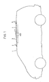
- the roof opening device comprises four panels arranged in alignment with the roof 1 of the vehicle as visible in FIG. 1.
- a first small front panel or orientable flap 2 mounted at articulation and able to open outwards of the passenger compartment of the vehicle, allows ventilation of the air in the front passengers.
- a large panel 3 is arranged at the rear of the shutter 2, this panel 3 being able to be ajar to ventilate the front environment of the passenger compartment and slide over the roof 1, thus freeing an opening on the front environment of the passenger compartment .
- the movable flap 2 acts as a deflector, thereby orienting the air streams so that they do not enter the passenger compartment thereby causing noise and turbulence.
- a third panel 4 can be arranged at the rear of the panel 3. This panel 4 can be fixed or removable to release an opening in the rear middle of the roof 1.
- a fourth small panel or orientable flap 5 is disposed at the rear of the panel 4 and can be ajar towards the outside of the passenger compartment.
- the different panels 3, 4, and adjustable shutters 2, 5, can be made of glass, sheet metal, synthetic material or any other material.
- At least one of the panels 3, 4, may include a blackout curtain 400 extending over all or part of the surface of said panel in the case of transparent panels.
- Each of said orientable flaps 2, 5, of substantially rectangular shape, cooperate at each of their respective transverse ends with a cam 20, 50, for guiding rollers 21, 51, integral with control carriages 22, 52, as visible in FIG. 2.
- Each orientable flap 2, 5 is associated with a set of two identical cams respectively 20, 50.
- the control carriages 22, 52 are movable in alternating translation in the longitudinal direction of the roof, this direction being materialized by a set of rails 25, 55, arranged on either side of the orientable flaps 2, 5, in which the said carriages 22, 52 move, the rails 25, 55, respectively guiding the carriages 22, 52.
- the diagonally opposite control carriages 22, 52, respectively of the two orientable flaps 2, 5, are linked in pairs by a cable respectively 100, 200, so that said diagonally opposite carriages move simultaneously in translation but in an opposite direction.
- the cables 100, 200 are driven simultaneously but in an opposite direction by a pinion 300 mounted on an axis, said pinion being able to be rotated by a crank or an electric motor.
- Each of said flaps 2, 5, are mounted with articulation on axes respectively 28, 58, placed substantially perpendicular to the longitudinal axis of the roof and at the front of each of said orientable flaps, so that these can half open by rotation around said respective axes.
- Said cams 20, 50, respectively of said orientable flaps 2, 5, have a trapezoidal waveform, so that the translational movement of the carriages 22, 52, by actuation of the cables 100, 200, causes a movement of articulation of said orientable flaps 2, 5, due to the displacement of the rollers 21, 51, in the cams 20, 50. Thanks to the particular shape of the cams 20, 50, the orientable flaps 2, 5 can be selectively or simultaneously opened or closed.
- the movable panel 3 cooperates with a set of two cams 30, arranged at its transverse ends for guiding the rollers 21 integral with the carriages 25.
- the panel 3 is mounted with articulation on an axis 38 placed substantially perpendicular to the longitudinal axis of the roof 1 and at the front of the said panel 3.
- the axis 38 can move in translation in a direction parallel to the longitudinal axis of the roof in the front direction of the roof towards the rear of the roof.
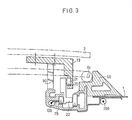
- the panels 3, 4, and the orientable flaps 2, 5, are kept rigid in the roof 1 thanks to a frame 60 of substantially rectangular shape, of molded synthetic material or of molded aluminum.
- the frame has a curved profile welded edge to edge, glued or assembled by any other means.
- the sunroof with several panels can be fitted in the case of an original or second fit solution in the vehicle roof.
- the attachment with the roof is carried out by a counter-frame 62 assembled to the frame 60.
- Seals 61 are arranged around each of the panels 3, 4, and orientable flaps 2, 5, so as to avoid d inside the passenger compartment, in the closed position of the flaps and panels as visible in FIG. 3.
- the orientable flap 2 it is assembled to a slide 23 mounted at articulation around the axis 28.
- Each orientable flap 2, 5, and the panel 3 has a set of specific slides in which the cams 20, 30, 50 are respectively disposed.
- a leaf spring 90 for holding the said flap in the open position is placed between the rail 25 and the slide 23 so that in the ajar position of the flap 2, the latter is held in this position by the action of the leaf spring 90 working in compression.
- the roof opening device being symmetrical with respect to the longitudinal axis of the roof, we will now describe its operation by only considering the action of the elements located on one of its side faces, more precisely the left side face as shown in Figures 4a to 4e.
- the cam 20 associated with the orientable flap 2 having the shape of a wave comprising a crest and a hollow.
- the rollers 21, 51, cooperating with the cams 20, 50, associated with the two flaps 2, 5 are positioned respectively at A and A ′, corresponding to the crests of the cams 20, 50, as visible in FIG. 4a.
- the carriage 22 is moved in translation towards the front of the roof by means of the cable 100 over a distance d
- the carriage 52 is moved in translation towards the rear of the roof under the action of the cable 200, over a distance d, the cables 100, 200, acting opposite through the pinion 300.
- the rollers 21, 51 are positioned respectively on a crest B of the cam 20 and in a recess B ′ of the cam 50.
- the positioning of the roller 51 in the hollow B ′ of the cam 50 has the effect of raising the flap 5 by rotation of the latter around its axis 58, while the flap 2 remains in the closed position as visible in FIG. 4b.
- a panel 3 ajar and movable in translation is disposed behind the flap 2.
- the panel 3 cooperates with a set of cams 30 in the form of a half-wave and having a crest F and a hollow E.
- the pinion 300 is rotated anti-clockwise. Under this action, the carriage 22 is moved in translation towards the rear of the roof over a distance d ⁇ , while the carriage 52 is moved in translation towards the front of the roof over the same distance d ⁇ .
- the roller 21 is positioned in a hollow D of the cam 20 thus opening the shutter 2
- the roller 51 is similarly positioned in a hollow D ′ of the cam 50, also also opening the shutter 5 as visible in figure 4d.
- the cams 20, 50 each have a respective through end D, D ′, corresponding to a hollow, so that the rollers 21, 51 can leave the cam in which they slide when they precisely reach this open end.
- the cam 30 also has a through end corresponding to a crest F, so that the roller 21 can engage in the cam 30 when it comes to the right of this open end.
Landscapes
- Engineering & Computer Science (AREA)
- Mechanical Engineering (AREA)
- Body Structure For Vehicles (AREA)
- Power-Operated Mechanisms For Wings (AREA)
- Fittings On The Vehicle Exterior For Carrying Loads, And Devices For Holding Or Mounting Articles (AREA)
Applications Claiming Priority (2)
| Application Number | Priority Date | Filing Date | Title |
|---|---|---|---|
| FR8812546A FR2636892B1 (fr) | 1988-09-26 | 1988-09-26 | Dispositif d'ouverture de toit a au moins deux volets orientables |
| FR8812546 | 1988-09-26 |
Publications (2)
| Publication Number | Publication Date |
|---|---|
| EP0362028A1 true EP0362028A1 (de) | 1990-04-04 |
| EP0362028B1 EP0362028B1 (de) | 1992-04-15 |
Family
ID=9370388
Family Applications (1)
| Application Number | Title | Priority Date | Filing Date |
|---|---|---|---|
| EP89402583A Expired - Lifetime EP0362028B1 (de) | 1988-09-26 | 1989-09-21 | Schiebedach mit zumindest zwei steuerbaren Deckelteilen |
Country Status (5)
| Country | Link |
|---|---|
| US (1) | US5031959A (de) |
| EP (1) | EP0362028B1 (de) |
| JP (1) | JP2621997B2 (de) |
| DE (1) | DE68901238D1 (de) |
| FR (1) | FR2636892B1 (de) |
Cited By (7)
| Publication number | Priority date | Publication date | Assignee | Title |
|---|---|---|---|---|
| FR2694522A1 (fr) * | 1992-08-07 | 1994-02-11 | Heuliez Webasto | Dispositif ouvrant comportant un déflecteur de vent et véhicule le comprenant. |
| EP0733506A1 (de) * | 1995-03-24 | 1996-09-25 | Dr.Ing.h.c. F. Porsche Aktiengesellschaft | Fahrzeugdach |
| DE19620879A1 (de) * | 1996-05-23 | 1997-11-27 | Bayerische Motoren Werke Ag | Be- und Entlüftungseinrichtung an einem Fahrzeugdach |
| EP0853012A1 (de) * | 1997-01-10 | 1998-07-15 | WEBASTO KAROSSERIESYSTEME GmbH | Windleitelement für ein Fahrzeugdach |
| US5833305A (en) * | 1995-12-30 | 1998-11-10 | Webasto Karosseriesysteme Gmbh | Wind deflector element for a motor vehicle roof |
| US6412858B2 (en) | 2000-03-21 | 2002-07-02 | Webasto Vehicle Systems International Gmbh | Motor vehicle roof with ventilator means |
| FR2898831A1 (fr) * | 2006-03-24 | 2007-09-28 | Heuliez Sa | Toit a element mobile |
Families Citing this family (19)
| Publication number | Priority date | Publication date | Assignee | Title |
|---|---|---|---|---|
| DE4112246A1 (de) * | 1991-04-15 | 1992-10-22 | Rockwell Golde Gmbh | Dachkonstruktion fuer fahrzeuge |
| US5768834A (en) * | 1995-08-31 | 1998-06-23 | Pinder; Robert C. | Rain shield |
| DE19802301A1 (de) * | 1998-01-22 | 1999-07-29 | Bosch Gmbh Robert | Windabweiser für ein mit einem Schiebedach ausgestattetes Kraftfahrzeug |
| DE19822006A1 (de) * | 1998-05-15 | 1999-11-18 | Bayerische Motoren Werke Ag | Windabweiseranordnung an einem Fahrzeugdach |
| DE19849840C1 (de) * | 1998-10-29 | 2000-02-17 | Webasto Karosseriesysteme | Fahrzeugdach |
| US6045176A (en) * | 1999-04-06 | 2000-04-04 | Shoup; Chris M. | Detachable sun roof vent assembly |
| US6174025B1 (en) | 1999-08-31 | 2001-01-16 | Daimlerchrysler Corporation | Sun roof air dam wind noise reducer |
| DE19941984C1 (de) * | 1999-09-03 | 2000-10-19 | Porsche Ag | Mehrteiliges Schiebedach für ein Kraftfahrzeug |
| NL1013832C2 (nl) * | 1999-12-13 | 2001-06-14 | Inalfa Ind Bv | Open-dakconstructie voor een voertuig. |
| NL1015492C2 (nl) * | 2000-06-21 | 2001-12-28 | Inalfa Ind Bv | Open-dakconstructie voor een voertuig. |
| DE10208909C1 (de) * | 2002-02-28 | 2003-12-04 | Webasto Vehicle Sys Int Gmbh | Öffnungsfähiges Fahrzeugdach |
| DE10208907B4 (de) * | 2002-02-28 | 2005-09-08 | Webasto Ag | Öffnungsfähiges Fahrzeugdach |
| US6641201B1 (en) * | 2002-09-17 | 2003-11-04 | General Motors Corporation | Convertible bed cover for a vehicle |
| DE10248344A1 (de) * | 2002-10-17 | 2004-05-06 | Wilhelm Karmann Gmbh | Kraftfahrzeug |
| DE10339909B4 (de) * | 2003-08-29 | 2007-05-24 | Webasto Ag | Öffnungsfähiges Fahrzeugdach mit Windabweiser |
| DE102008018577A1 (de) * | 2008-04-12 | 2009-10-15 | Dr. Ing. H.C. F. Porsche Aktiengesellschaft | Kraftfahrzeug mit einer Dachanordnung |
| DE102008024891B4 (de) * | 2008-05-16 | 2019-09-12 | Dr. Ing. H.C. F. Porsche Aktiengesellschaft | Kraftfahrzeug |
| FR3020344B1 (fr) * | 2014-04-24 | 2016-05-13 | Airbus Operations Sas | Assemblage pour un aeronef comportant un panneau d'acces mobile |
| JP6375759B2 (ja) * | 2014-07-31 | 2018-08-22 | アイシン精機株式会社 | サンルーフ装置 |
Citations (3)
| Publication number | Priority date | Publication date | Assignee | Title |
|---|---|---|---|---|
| GB2113623A (en) * | 1982-01-28 | 1983-08-10 | Ford Motor Co | Sliding roof for motor vehicles |
| GB2147943A (en) * | 1983-09-29 | 1985-05-22 | Johnan Seisakusho | Sunroof panel opening/closing apparatus |
| EP0218020A2 (de) * | 1985-09-10 | 1987-04-15 | Ford-Werke Aktiengesellschaft | Ausstell-Schiebedach für Kraftfahrzeuge |
Family Cites Families (10)
| Publication number | Priority date | Publication date | Assignee | Title |
|---|---|---|---|---|
| DE1162212B (de) * | 1960-07-20 | 1964-01-30 | H T Golde G M B H & Co K G | Kraftfahrzeug mit starrem Schiebedeckel |
| DE2724457C3 (de) * | 1976-05-31 | 1981-09-10 | Louis Heuliez S.A., Cerisay, Deux Sevres | Zusammenschiebbares Dach eines Fahrzeugs |
| US4178036A (en) * | 1977-10-17 | 1979-12-11 | American Sunroof Corporation | Positive lock mechanism for vehicular sliding roof panels |
| JPS57103218U (de) * | 1980-12-17 | 1982-06-25 | ||
| FR2527256A2 (fr) * | 1982-03-01 | 1983-11-25 | Heuliez Dea | Dispositif d'ouverture a surface decouvrable, notamment toit ouvrant pour vehicule automobile |
| JPS60110007U (ja) * | 1983-12-28 | 1985-07-26 | ダイキヨ−・ベバスト株式会社 | 乗物の屋根窓における換気装置 |
| JPH022668Y2 (de) * | 1984-10-30 | 1990-01-23 | ||
| JPS62110021U (de) * | 1985-12-28 | 1987-07-14 | ||
| JPS63192125A (ja) * | 1987-02-04 | 1988-08-09 | Nippon Denso Co Ltd | マイクロプロセツサの入力回路 |
| DE3732548A1 (de) * | 1987-09-26 | 1989-04-20 | Ford Werke Ag | Ausstell-schiebedach fuer kraftfahrzeuge |
-
1988
- 1988-09-26 FR FR8812546A patent/FR2636892B1/fr not_active Expired - Lifetime
-
1989
- 1989-09-21 DE DE8989402583T patent/DE68901238D1/de not_active Expired - Fee Related
- 1989-09-21 EP EP89402583A patent/EP0362028B1/de not_active Expired - Lifetime
- 1989-09-26 JP JP1250392A patent/JP2621997B2/ja not_active Expired - Fee Related
- 1989-09-26 US US07/412,437 patent/US5031959A/en not_active Expired - Lifetime
Patent Citations (3)
| Publication number | Priority date | Publication date | Assignee | Title |
|---|---|---|---|---|
| GB2113623A (en) * | 1982-01-28 | 1983-08-10 | Ford Motor Co | Sliding roof for motor vehicles |
| GB2147943A (en) * | 1983-09-29 | 1985-05-22 | Johnan Seisakusho | Sunroof panel opening/closing apparatus |
| EP0218020A2 (de) * | 1985-09-10 | 1987-04-15 | Ford-Werke Aktiengesellschaft | Ausstell-Schiebedach für Kraftfahrzeuge |
Cited By (8)
| Publication number | Priority date | Publication date | Assignee | Title |
|---|---|---|---|---|
| FR2694522A1 (fr) * | 1992-08-07 | 1994-02-11 | Heuliez Webasto | Dispositif ouvrant comportant un déflecteur de vent et véhicule le comprenant. |
| EP0733506A1 (de) * | 1995-03-24 | 1996-09-25 | Dr.Ing.h.c. F. Porsche Aktiengesellschaft | Fahrzeugdach |
| US5836643A (en) * | 1995-03-24 | 1998-11-17 | Dr. Ing. H.C.F. Porsche Ag | Vehicle roof |
| US5833305A (en) * | 1995-12-30 | 1998-11-10 | Webasto Karosseriesysteme Gmbh | Wind deflector element for a motor vehicle roof |
| DE19620879A1 (de) * | 1996-05-23 | 1997-11-27 | Bayerische Motoren Werke Ag | Be- und Entlüftungseinrichtung an einem Fahrzeugdach |
| EP0853012A1 (de) * | 1997-01-10 | 1998-07-15 | WEBASTO KAROSSERIESYSTEME GmbH | Windleitelement für ein Fahrzeugdach |
| US6412858B2 (en) | 2000-03-21 | 2002-07-02 | Webasto Vehicle Systems International Gmbh | Motor vehicle roof with ventilator means |
| FR2898831A1 (fr) * | 2006-03-24 | 2007-09-28 | Heuliez Sa | Toit a element mobile |
Also Published As
| Publication number | Publication date |
|---|---|
| FR2636892B1 (fr) | 1990-12-07 |
| FR2636892A1 (fr) | 1990-03-30 |
| EP0362028B1 (de) | 1992-04-15 |
| DE68901238D1 (de) | 1992-05-21 |
| JP2621997B2 (ja) | 1997-06-18 |
| JPH02185825A (ja) | 1990-07-20 |
| US5031959A (en) | 1991-07-16 |
Similar Documents
| Publication | Publication Date | Title |
|---|---|---|
| EP0362028A1 (de) | Schiebedach mit zumindest zwei steuerbaren Deckelteilen | |
| EP0544582B1 (de) | Führungsvorrichtung einer Schiebeöffnung, zum Beispiel einer Schiebetür, insbesondere für ein Kraftfahrzeug | |
| EP0403388A1 (de) | Öffnungs-, Verschluss- und Ausstellvorrichtung für eine verstellbare Platte im Verhältnis zu einer festen Oberfläche, insbesondere für ein Kraftfahrzeugschiebedach | |
| FR3056959B1 (fr) | Mecanisme pour un element de carrosserie de vehicule | |
| EP0524051A1 (de) | Mit Hebeln versehenes kippbares Schiebedach | |
| EP0810930A1 (de) | Öffnungsfähiges dach mit einem vorderen und einem hinteren, unabhängig betätigbaren paneel | |
| EP2694306B2 (de) | Glasdach mit verschiebbarer und schwenkbarer mobiler platte | |
| FR2833209A1 (fr) | Dispositif d'obturation d'une baie menagee dans la carrosserie d'un vehicule, et vehicule correspondant | |
| FR2723612A1 (fr) | Ensemble de vitrage a opacite reglable. | |
| FR2833212A1 (fr) | Dispositif d'obturation d'une baie menagee dans un vehicule a rail de coulissement unique, et vehicule correspondant | |
| EP3169543A1 (de) | Glasdach mit einer durch schiffchen gesteuerten mobilen platte | |
| EP3792132B1 (de) | Fensteröffnug einer rollendem eisenbahnausrüstung | |
| WO2023104816A1 (fr) | Dispositif d'obstruction de passage et portillon d'accès associé | |
| EP3650303B1 (de) | Waggon eines schienenfahrzeugs mit verdunkelungsvorrichtung des verglasten öffnungselements | |
| EP0220976A1 (de) | Schiebedach für Kraftfahrzeuge | |
| FR2985224A1 (fr) | Pavillon vitre de vehicule, equipe d'un panneau mobile coulissant, et vehicule correspondant | |
| EP1867511B1 (de) | Fahrzeug mit nach hinten blockiertem Dach und Verfahren zur Steuerung dieses Dachs | |
| FR2983129A1 (fr) | Pavillon vitre a panneau mobile coulissant et entrebaillant. | |
| EP0401080A1 (de) | Abdichtungssystem für Fahrzeugtürfenster und Türen mit diesem System | |
| EP1281549B1 (de) | Steuervorrichtung zur Verstellung von bewegbaren Elementen eines Abdeckteils für einen Innenraum von Kraftfahrzeugen | |
| EP3578401A1 (de) | Glasdach mit einem beweglichen paneel, das über schlitten mit synchronisierter bewegung gesteuert wird | |
| EP1679213A1 (de) | Schiebetür für Motorfahrzeug und korrespondierendes Fahrzeug | |
| EP1598513A1 (de) | Fahrzeugtür mit Schiebefenster. | |
| FR2951406A1 (fr) | Vehicule dote d'une porte laterale coulissante integrant une partie du pavillon | |
| EP1772579A1 (de) | Schiebetür mit Führungsvorrichtung |
Legal Events
| Date | Code | Title | Description |
|---|---|---|---|
| PUAI | Public reference made under article 153(3) epc to a published international application that has entered the european phase |
Free format text: ORIGINAL CODE: 0009012 |
|
| AK | Designated contracting states |
Kind code of ref document: A1 Designated state(s): DE GB IT NL |
|
| 17P | Request for examination filed |
Effective date: 19900430 |
|
| 17Q | First examination report despatched |
Effective date: 19910328 |
|
| GRAA | (expected) grant |
Free format text: ORIGINAL CODE: 0009210 |
|
| AK | Designated contracting states |
Kind code of ref document: B1 Designated state(s): DE GB IT NL |
|
| ITF | It: translation for a ep patent filed | ||
| REF | Corresponds to: |
Ref document number: 68901238 Country of ref document: DE Date of ref document: 19920521 |
|
| GBT | Gb: translation of ep patent filed (gb section 77(6)(a)/1977) | ||
| PLBE | No opposition filed within time limit |
Free format text: ORIGINAL CODE: 0009261 |
|
| STAA | Information on the status of an ep patent application or granted ep patent |
Free format text: STATUS: NO OPPOSITION FILED WITHIN TIME LIMIT |
|
| 26N | No opposition filed | ||
| REG | Reference to a national code |
Ref country code: GB Ref legal event code: IF02 |
|
| PGFP | Annual fee paid to national office [announced via postgrant information from national office to epo] |
Ref country code: NL Payment date: 20060903 Year of fee payment: 18 |
|
| PGFP | Annual fee paid to national office [announced via postgrant information from national office to epo] |
Ref country code: DE Payment date: 20060914 Year of fee payment: 18 |
|
| PGFP | Annual fee paid to national office [announced via postgrant information from national office to epo] |
Ref country code: GB Payment date: 20060920 Year of fee payment: 18 |
|
| PGFP | Annual fee paid to national office [announced via postgrant information from national office to epo] |
Ref country code: IT Payment date: 20060930 Year of fee payment: 18 |
|
| GBPC | Gb: european patent ceased through non-payment of renewal fee |
Effective date: 20070921 |
|
| PG25 | Lapsed in a contracting state [announced via postgrant information from national office to epo] |
Ref country code: NL Free format text: LAPSE BECAUSE OF NON-PAYMENT OF DUE FEES Effective date: 20080401 |
|
| NLV4 | Nl: lapsed or anulled due to non-payment of the annual fee |
Effective date: 20080401 |
|
| PG25 | Lapsed in a contracting state [announced via postgrant information from national office to epo] |
Ref country code: DE Free format text: LAPSE BECAUSE OF NON-PAYMENT OF DUE FEES Effective date: 20080401 |
|
| PG25 | Lapsed in a contracting state [announced via postgrant information from national office to epo] |
Ref country code: GB Free format text: LAPSE BECAUSE OF NON-PAYMENT OF DUE FEES Effective date: 20070921 |
|
| PG25 | Lapsed in a contracting state [announced via postgrant information from national office to epo] |
Ref country code: IT Free format text: LAPSE BECAUSE OF NON-PAYMENT OF DUE FEES Effective date: 20070921 |