EP0360342A2 - Elektrobackofen in Doppelgehäusebauart mit gleichmässiger Wärmeabstrahlung , insbesondere für die Zubereitung von Kuchen und Süssigkeiten im allgemeinen - Google Patents
Elektrobackofen in Doppelgehäusebauart mit gleichmässiger Wärmeabstrahlung , insbesondere für die Zubereitung von Kuchen und Süssigkeiten im allgemeinen Download PDFInfo
- Publication number
- EP0360342A2 EP0360342A2 EP89202344A EP89202344A EP0360342A2 EP 0360342 A2 EP0360342 A2 EP 0360342A2 EP 89202344 A EP89202344 A EP 89202344A EP 89202344 A EP89202344 A EP 89202344A EP 0360342 A2 EP0360342 A2 EP 0360342A2
- Authority
- EP
- European Patent Office
- Prior art keywords
- oven
- box structure
- walls
- cavity
- door
- Prior art date
- Legal status (The legal status is an assumption and is not a legal conclusion. Google has not performed a legal analysis and makes no representation as to the accuracy of the status listed.)
- Granted
Links
- 238000002360 preparation method Methods 0.000 title claims abstract description 15
- 235000009508 confectionery Nutrition 0.000 title description 2
- 238000010411 cooking Methods 0.000 claims abstract description 20
- 235000013305 food Nutrition 0.000 claims abstract description 17
- 229910052751 metal Inorganic materials 0.000 claims abstract description 3
- 239000002184 metal Substances 0.000 claims abstract description 3
- 238000010438 heat treatment Methods 0.000 claims description 13
- 239000004411 aluminium Substances 0.000 claims description 2
- 229910052782 aluminium Inorganic materials 0.000 claims description 2
- XAGFODPZIPBFFR-UHFFFAOYSA-N aluminium Chemical compound [Al] XAGFODPZIPBFFR-UHFFFAOYSA-N 0.000 claims description 2
- 230000000295 complement effect Effects 0.000 claims description 2
- 239000004020 conductor Substances 0.000 claims description 2
- 239000003517 fume Substances 0.000 claims description 2
- 238000005192 partition Methods 0.000 claims description 2
- 125000006850 spacer group Chemical group 0.000 description 3
- 238000009304 pastoral farming Methods 0.000 description 2
- 230000002093 peripheral effect Effects 0.000 description 2
- 230000008878 coupling Effects 0.000 description 1
- 238000010168 coupling process Methods 0.000 description 1
- 238000005859 coupling reaction Methods 0.000 description 1
- 238000013021 overheating Methods 0.000 description 1
- 230000005855 radiation Effects 0.000 description 1
- 230000003134 recirculating effect Effects 0.000 description 1
Images

Classifications
-
- H—ELECTRICITY
- H05—ELECTRIC TECHNIQUES NOT OTHERWISE PROVIDED FOR
- H05B—ELECTRIC HEATING; ELECTRIC LIGHT SOURCES NOT OTHERWISE PROVIDED FOR; CIRCUIT ARRANGEMENTS FOR ELECTRIC LIGHT SOURCES, IN GENERAL
- H05B6/00—Heating by electric, magnetic or electromagnetic fields
- H05B6/64—Heating using microwaves
- H05B6/647—Aspects related to microwave heating combined with other heating techniques
- H05B6/6473—Aspects related to microwave heating combined with other heating techniques combined with convection heating
-
- F—MECHANICAL ENGINEERING; LIGHTING; HEATING; WEAPONS; BLASTING
- F24—HEATING; RANGES; VENTILATING
- F24C—DOMESTIC STOVES OR RANGES ; DETAILS OF DOMESTIC STOVES OR RANGES, OF GENERAL APPLICATION
- F24C15/00—Details
- F24C15/32—Arrangements of ducts for hot gases, e.g. in or around baking ovens
- F24C15/322—Arrangements of ducts for hot gases, e.g. in or around baking ovens with forced circulation
- F24C15/325—Arrangements of ducts for hot gases, e.g. in or around baking ovens with forced circulation electrically-heated
Definitions
- This invention relates to an electric oven comprising a housing enclosing a cavity provided on at least one wall with electrical resistance elements.
- temperature differences even of some tens of degrees can exist within said cavity, which can be particularly inconvenient during food preparation.
- temperature differences can lead for example to good surface cooking (or colour) of those food parts present in the high temperature zones and lesser surface cooking of other parts present in those cavity zones in which the temperature is lower.
- This drawback is particularly important in the preparation of cakes and sweets in general. This is because in such cases those parts of the cake located in the hotter zones of the oven cavity become properly cooked whereas those parts located in the cooler zones remain insufficiently cooked.
- the overall object of the present invention is to provide an oven of the aforesaid type which overcomes the drawbacks of known ovens.
- the object of the invention is to provide an oven which allows uniform preparation, and in particular cooking, of the food placed in it.
- an electric oven of the aforesaid type characterised by providing in its cavity a metal box structure which is open on one side and in which the food is disposed during its preparation, said box structure being positioned in such a manner as to create an interspace between its walls and the walls of the oven cavity.
- the oven is of the ventilated type to create forced air circulation through the interspaces present between the walls of its cavity and the box structure.
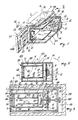
- FIGS 1 and 2 show a ventilated oven 1 provided with an inner cavity 6 (called hereinafter the heating chamber) provided with a roof 4, a lower wall 5 and an end wall 8 beyond which an electrical resistance element is provided in proximity to a grille 9 associated with said end wall 9.
- a fan 10 inserted in a compartment 11 present between said end wall 8 and the rear wall 12 of the housing 100 of the oven 1.
- Said fan 10 for example of the tangential type is provided with a motor 13 located in said compartment 11 to obtain forced air circulation within the oven 1.
- Said fan 10 feeds the air forcibly into the heating chamber 6 through the apertures 14 (arrows F) and draws in said air (arrows G) through the grille 9.
- the fan 10 is of the axial type.
- the forced air is fed into the heating chamber 6 through the grille 9 and drawn into the compartment 11 through the apertures 14.
- the usual deflectors are provided in proximity to the apertures 14 to allow good air recirculation through the compartment 11.
- a box structure 16 open on one side 17 is disposed in a suitable manner on the lower wall 5 of the heating chamber 6 and is secured in known manner.
- Said structure 16 is kept at a short but equal distance from the upper wall or roof 4 and from the lower wall 5 of the heating chamber 6 by spacers 61 provided on the lower wall 21(on which the food is placed for preparation) and on the upper wall or roof 20 of said structure 16.
- This latter also comprises side walls 18 and an end wall 19. In this manner between said walls 18, 19, 20 and 21 of the structure 16 (defining a cooking chamber 16A) and the side walls 22, roof 4, end wall 8 and lower wall 5 of the heating chamber 6 there are created identical interspaces 23 through which forced air circulation takes place.
- the spacers 61 also act as forced air deflectors and direct this air from the upper and lower parts of the structure 16 (arrows F) to its side parts (arrow W) to enclose the structure 16 with said flow of air heated by the resistance elements 7 located in proximity to the fan 10, this air then being drawn in by the fan 10 through the grille 9.
- the hot air which grazes the box structure 16 heats the walls 18, 19, 20 and 21 of said structure. Said walls then heat the food in said structure by radiation. As all the walls 18, 19, 20 and 21 are substantially at the same temperature the irradiation of the food is very uniform and its preparation is very satisfactory.
- the box structure 16 is positioned with its open side 17 towards the aperture in the housing 100 of the oven 1.
- This aperture is closed by a door 24 which in the embodiments of Figures 1 and 2 and of Figure 3 is provided with an inner projecting part 25 to enable the open side 17 of the box structure 16 to be also closed.
- an interspace 62 having upper and lower apertures 62A and side apertures 62B, and of width substantially equal to the width of the side 17 of the door 16, so that the air can circulate through it in order to graze said structure 16 also on its front side.
- said air enters the interspace 62 through the apertures 62A and leaves through the apertures 62B so as to be able to externally graze the side walls 18 of the box structure 16 after grazing the upper wall 20 and lower wall 21.
- the box structure 16 is provided with its own door, and in this case the door 24 of the oven 1 is not provided with the projection 25, said door 24 being only a short distance from that of the structure 16 to enable forced air to circulate between them.
- the structure 16 can also be provided with a resistance element, advantageously of silk-screen application, disposed on one of its walls such as the upper wall 20. Said resistance element 50 enables a food placed in the cooking chamber 16A of the structure 16 to be browned to the required extent, or grilled.
- a resistance element advantageously of silk-screen application
- a fan 67 can be provided in the structure 16 and be fitted to the drive shaft 68 of the fan 10, to be driven by the motor 13 of this latter.
- Said fan 67 (which as in the case of the fan 10 can be tengential or axial) is located in a compartment 63 defined between a partition wall 64 and the end wall 19 of the structure 16.
- the wall 64 is provided with apertures 66 and a grille 65 located in front of the fan 67.
- said fan 67 can be separated from the drive shaft 68 by means of a coupling 69 which can be operated from the outside of the oven 1, so that said fan 67 need be operated only when necessary.
- a known fan 200 is provided (see Figure 3) on the outside of said oven 1 beyond the rear wall 12, and is advantageously operated by the motor 13 of the fan 10 disposed in the oven.
- Said fan 200 disposed in a cavity 210 provided in the cabinet 190, creates forced air circulation around the oven 1 to prevent overheating of the cabinet 190 during the use of said oven.
- a passage (represented and indicated by 72 in Figure 3) can be provided within the roof 20 of the box structure 16 or within its door (if provided) or within the projecting part 25 of the door 24 of the oven 1, to allow the fumes released within the cooking chamber 16A during food preparation to be removed by natural convection.
- This passage or flue which can advantageously be of the type which can be closed by an automatically or manually operated member or damper, enables the moisture released within the cooking chamber 16A during food preparation to be discharged to the outside.
- At least one temperature sensor (represented and indicated by 73 in Figure 3) disposed for example in the roof 20 of said structure.
- these walls are advantageously lined on their inner side with thin sheets of a good temperature-conducting material such as aluminium.
- the box structure 16, defining substantially a cooking chamber 16A of uniform temperature can also be removably insertable into the heating chamber 6 of the oven 1 and removably fixable therein. In this manner the user can use the structure 16 only in particular situations, such as to obtain optimum preparation of a cake.
- the structure 16 can also be of the foldable type, in which case known fixing elements (such as spring clips) are provided on the walls of said structure to stabilize said walls during the use of the structure 16 in the oven 1.
- known fixing elements such as spring clips
- gaskets are provided on the ends of the foldable sides to provide the thermal seals necessary for proper operation of the oven.
- a closure plate 83 is disposed facing the door 24 around that part of the structure close to said door to hermetically seal said structure within the heating chamber 6.
- Said plate 83 is substantially of annular shape with a contour complementary to that of the cavity or heating chamber 6 of the oven 1. In this manner the plate can be mounted on the structure 16 and thus be introduced into the oven 1.
- the plate 83 has a peripheral shape such as to enable it to engage both the walls 4, 5, 22 of the cavity 6 of the oven 1 and the box structure 16. On said peripheral part there are also provided known means for obtaining a sealed engagement.
- the plate 83 prevents the forced hot air circulating within the heating chamber 6 of the oven 1 from also grazing the front of the box structure 16.
- the spacers 61 are provided as stated, and act as deflectors for the forced air.
- the roof or upper wall 20 and the lower wall 21 of the structure 16 have dimensions such that they project laterally from said structure so as to create with the side walls 22 ofthe heating chamber 6 the interspace 88 for recirculating the forced air to the sides to said structure 16.
- ducts 84 which channel the air moved by the fan 10 and guide it towards side apertures 85 provided in the roof 20 and in said walls 21.
- the hot air can pass into the side interspaces 88 and be drawn in by the fan 10 through said apertures (arrows W and G).
- a food 50A such as a cake
- the cake 50A is firstly positioned in the cooking chamber 16A of the box structure 16 after which the door 24 of the oven 1 is closed. In this manner (in the example illustrated in said figures) said box structure is also closed.
- the oven 1 is switched on and the fan 10 operated to circulate forced air, the resistance element 7 thus generating heat to heat the air circulated by the fan 10.
- This air grazes the structure 16 to heat its walls 18, 19, 20 and 21 in a substantially uniform manner. Said walls radiate heat in such a manner as to create within the cooking chamber 16A a uniform temperature enabling the cake 50A to cook equally in all its parts, and in particular to possess a uniform surface colour when cooking is complete.
- An oven constructed in accordance with the present invention enables food to be properly cooked in all its parts and to obtain a surface coloration which is more uniform than that obtainable with ovens of the state of the art.
Landscapes
- Engineering & Computer Science (AREA)
- Chemical & Material Sciences (AREA)
- Combustion & Propulsion (AREA)
- Mechanical Engineering (AREA)
- General Engineering & Computer Science (AREA)
- Physics & Mathematics (AREA)
- Electromagnetism (AREA)
- Electric Stoves And Ranges (AREA)
- Baking, Grill, Roasting (AREA)
- Electric Ovens (AREA)
- Constitution Of High-Frequency Heating (AREA)
Applications Claiming Priority (2)
| Application Number | Priority Date | Filing Date | Title |
|---|---|---|---|
| IT2206488 | 1988-09-23 | ||
| IT8822064A IT1227212B (it) | 1988-09-23 | 1988-09-23 | Forno elettrico, a doppia camera ad irraggiamento uniforme, particolarmente per la preparazione di torte e dolci in generale |
Publications (3)
| Publication Number | Publication Date |
|---|---|
| EP0360342A2 true EP0360342A2 (de) | 1990-03-28 |
| EP0360342A3 EP0360342A3 (en) | 1990-11-28 |
| EP0360342B1 EP0360342B1 (de) | 1992-12-02 |
Family
ID=11190935
Family Applications (1)
| Application Number | Title | Priority Date | Filing Date |
|---|---|---|---|
| EP89202344A Expired EP0360342B1 (de) | 1988-09-23 | 1989-09-18 | Elektrobackofen in Doppelgehäusebauart mit gleichmässiger Wärmeabstrahlung , insbesondere für die Zubereitung von Kuchen und Süssigkeiten im allgemeinen |
Country Status (6)
| Country | Link |
|---|---|
| US (1) | US5142125A (de) |
| EP (1) | EP0360342B1 (de) |
| JP (1) | JPH0281301U (de) |
| DE (1) | DE68903716T2 (de) |
| ES (1) | ES2037944T3 (de) |
| IT (1) | IT1227212B (de) |
Families Citing this family (20)
| Publication number | Priority date | Publication date | Assignee | Title |
|---|---|---|---|---|
| GB9109435D0 (en) * | 1991-05-01 | 1991-06-26 | Stoves Ltd | Improvements in and relating to cookers |
| US5285719A (en) * | 1992-09-11 | 1994-02-15 | Gas Research Institute | Rapid frozen food thawing system |
| US5336867A (en) * | 1993-12-13 | 1994-08-09 | General Electric Company | Convection oven tapered air heating chamber |
| US5801362A (en) * | 1994-01-14 | 1998-09-01 | Hudson Standard Corporation | Portable electric oven with fan and motor arrangement for improved heated air flow and motor cooling |
| US5676870A (en) * | 1994-05-25 | 1997-10-14 | Ultravection International, Inc. | Convectively-enhanced radiant heat oven |
| US5588353A (en) * | 1995-07-18 | 1996-12-31 | Appliance Development Corp. | Automatic bread-making apparatus |
| US5584233A (en) * | 1995-07-18 | 1996-12-17 | Appliance Development Corp. | Automatic bread-making apparatus |
| US6919122B2 (en) | 1999-07-08 | 2005-07-19 | Saint-Gobain Performance Plastics Corporation | Flexible composites with integral flights for use in high-temperature food processing equipment and methods for producing the same |
| US6124572A (en) * | 1999-09-21 | 2000-09-26 | Spilger; Jon Barton | Food warmer cabinet having an improved drawer slide assembly |
| US6225603B1 (en) * | 1999-11-22 | 2001-05-01 | Electrinic Enterprise Ltd. | Electric oven |
| US6444955B1 (en) | 2000-09-27 | 2002-09-03 | Ultravection International, Inc. | Cooking enhancing convection oven and method of enhancing the cooking in a convection oven |
| EP2408263B1 (de) * | 2004-12-14 | 2014-02-12 | Enodis Corporation | Umwälzungs-/Konvektions-/Mikrowellenofen und Verfahren |
| KR100788810B1 (ko) * | 2005-03-31 | 2007-12-27 | 엘지전자 주식회사 | 조리기기 |
| KR101291272B1 (ko) * | 2006-10-12 | 2013-07-30 | 엘지전자 주식회사 | 조리기기 |
| CN102771523B (zh) * | 2008-01-28 | 2015-04-22 | 杜克制造公司 | 对流式炉 |
| US9080776B2 (en) * | 2008-08-26 | 2015-07-14 | General Electric Company | Fan apparency arrangement for an appliance |
| DE102008053145A1 (de) * | 2008-10-24 | 2010-04-29 | Rational Ag | Strömungsleitvorrichtung für ein Gargerät |
| US9513054B2 (en) * | 2014-07-18 | 2016-12-06 | Baxley Equipment Co | Fan for drying of lumber |
| US10260756B2 (en) | 2016-05-20 | 2019-04-16 | Electrolux Home Products, Inc. | Deflecting element for appliance doors |
| WO2018102166A1 (en) | 2016-11-29 | 2018-06-07 | Saint-Gobain Performance Plastics Corporation | Composite belt profile |
Family Cites Families (9)
| Publication number | Priority date | Publication date | Assignee | Title |
|---|---|---|---|---|
| CH345137A (fr) * | 1956-06-30 | 1960-03-15 | Ayat Andre | Cuisinière |
| GB960161A (en) * | 1961-05-18 | 1964-06-10 | William Green & Co Eccesfield | Improvements in or relating to electric cooking ranges |
| DE1454294A1 (de) * | 1962-12-21 | 1969-03-06 | Keating Richard T | Brat- und Backofen |
| DE2950946C2 (de) * | 1979-12-18 | 1984-08-09 | Bosch-Siemens Hausgeräte GmbH, 7000 Stuttgart | Backofen mit Umluftgebläse und Grillheizkörper |
| US4386558A (en) * | 1981-02-12 | 1983-06-07 | Holman J Harrison | Convection cooking equipment |
| DE8323718U1 (de) * | 1983-08-18 | 1984-02-02 | Binder, Peter Michael, Dipl.-Ing., 7200 Tuttlingen | Heizschrank |
| AU575743B2 (en) * | 1986-05-15 | 1988-08-04 | Kabushiki Kaisha Toshiba | Circulating air cooker |
| US4827106A (en) * | 1987-09-21 | 1989-05-02 | Hobart Corporation | Self-cleaning convection oven |
| US4829158A (en) * | 1988-01-06 | 1989-05-09 | Sunbeam Corporation | Portable electric oven utilizing recirculating high speed air for cooking |
-
1988
- 1988-09-23 IT IT8822064A patent/IT1227212B/it active
-
1989
- 1989-09-18 EP EP89202344A patent/EP0360342B1/de not_active Expired
- 1989-09-18 ES ES198989202344T patent/ES2037944T3/es not_active Expired - Lifetime
- 1989-09-18 DE DE8989202344T patent/DE68903716T2/de not_active Expired - Fee Related
- 1989-09-20 US US07/410,378 patent/US5142125A/en not_active Expired - Lifetime
- 1989-09-22 JP JP1989110403U patent/JPH0281301U/ja active Pending
Also Published As
| Publication number | Publication date |
|---|---|
| EP0360342A3 (en) | 1990-11-28 |
| EP0360342B1 (de) | 1992-12-02 |
| ES2037944T3 (es) | 1993-07-01 |
| US5142125A (en) | 1992-08-25 |
| DE68903716D1 (de) | 1993-01-14 |
| IT1227212B (it) | 1991-03-27 |
| IT8822064A0 (it) | 1988-09-23 |
| JPH0281301U (de) | 1990-06-22 |
| DE68903716T2 (de) | 1993-06-09 |
Similar Documents
| Publication | Publication Date | Title |
|---|---|---|
| EP0360342B1 (de) | Elektrobackofen in Doppelgehäusebauart mit gleichmässiger Wärmeabstrahlung , insbesondere für die Zubereitung von Kuchen und Süssigkeiten im allgemeinen | |
| EP0632875B1 (de) | Heissluftofen zum zubereiten von nahrung in heissluft | |
| US4357522A (en) | Baking oven | |
| EP1467154B1 (de) | Gargerät | |
| US4829158A (en) | Portable electric oven utilizing recirculating high speed air for cooking | |
| EP0751698B1 (de) | Mikrowellenofen mit Umwalzheizung | |
| EP3745030B1 (de) | Kochgerät | |
| EP0429822A1 (de) | Kombinierter Mikrowellen- und gezwungener Konvektionsofen | |
| EP1748255B1 (de) | Elektrischer Ofen | |
| CA2083992C (en) | Forced circulation oven door | |
| US5620623A (en) | Thermal blend convection oven | |
| CN1281963A (zh) | 热风对流式微波炉 | |
| US6723970B1 (en) | Ventilation system for a cooking appliance | |
| EP0768809B1 (de) | Schutzhaube für Konvektions- und Mikrowellenofen | |
| EP1058483B1 (de) | Mikrowellenofen mit Strahlungsheizelement | |
| CA1152573A (en) | Combination microwave/forced convection oven with a microwave transparent container | |
| EP1201998B1 (de) | Backröhre | |
| US3367316A (en) | Oven for closed door broiling | |
| JPH06281148A (ja) | 加熱調理器 | |
| CA1138937A (en) | Combination microwave and convection oven | |
| GB1601690A (en) | Fan assisted grill oven | |
| GB2230926A (en) | Microwave oven with improved cooling of the magnetron | |
| CN220859922U (zh) | 烹饪设备、集成灶 | |
| KR200150819Y1 (ko) | 매트장치채용 전자렌지 | |
| GB2198838A (en) | Forced-circulation cooking oven |
Legal Events
| Date | Code | Title | Description |
|---|---|---|---|
| PUAI | Public reference made under article 153(3) epc to a published international application that has entered the european phase |
Free format text: ORIGINAL CODE: 0009012 |
|
| AK | Designated contracting states |
Kind code of ref document: A2 Designated state(s): DE ES FR GB IT SE |
|
| PUAL | Search report despatched |
Free format text: ORIGINAL CODE: 0009013 |
|
| AK | Designated contracting states |
Kind code of ref document: A3 Designated state(s): DE ES FR GB IT SE |
|
| 17P | Request for examination filed |
Effective date: 19910523 |
|
| 17Q | First examination report despatched |
Effective date: 19910814 |
|
| GRAA | (expected) grant |
Free format text: ORIGINAL CODE: 0009210 |
|
| AK | Designated contracting states |
Kind code of ref document: B1 Designated state(s): DE ES FR GB IT SE |
|
| PG25 | Lapsed in a contracting state [announced via postgrant information from national office to epo] |
Ref country code: IT Free format text: LAPSE BECAUSE OF FAILURE TO SUBMIT A TRANSLATION OF THE DESCRIPTION OR TO PAY THE FEE WITHIN THE PRE;WARNING: LAPSES OF ITALIAN PATENTS WITH EFFECTIVE DATE BEFORE 2007 MAY HAVE OCCURRED AT ANY TIME BEFORE 2007. THE CORRECT EFFECTIVE DATE MAY BE DIFFERENT FROM THE ONE RECORDED.SCRIBED TIME-LIMIT Effective date: 19921202 |
|
| REF | Corresponds to: |
Ref document number: 68903716 Country of ref document: DE Date of ref document: 19930114 |
|
| RAP2 | Party data changed (patent owner data changed or rights of a patent transferred) |
Owner name: WHIRLPOOL EUROPE B.V. Owner name: IRE INDUSTRIE RIUNITE EURODOMESTICI S.R.L. |
|
| ET | Fr: translation filed | ||
| REG | Reference to a national code |
Ref country code: ES Ref legal event code: FG2A Ref document number: 2037944 Country of ref document: ES Kind code of ref document: T3 |
|
| PG25 | Lapsed in a contracting state [announced via postgrant information from national office to epo] |
Ref country code: ES Free format text: LAPSE BECAUSE OF EXPIRATION OF PROTECTION Effective date: 19930920 |
|
| PLBE | No opposition filed within time limit |
Free format text: ORIGINAL CODE: 0009261 |
|
| STAA | Information on the status of an ep patent application or granted ep patent |
Free format text: STATUS: NO OPPOSITION FILED WITHIN TIME LIMIT |
|
| 26N | No opposition filed | ||
| EAL | Se: european patent in force in sweden |
Ref document number: 89202344.1 |
|
| PGFP | Annual fee paid to national office [announced via postgrant information from national office to epo] |
Ref country code: SE Payment date: 19980904 Year of fee payment: 10 |
|
| PGFP | Annual fee paid to national office [announced via postgrant information from national office to epo] |
Ref country code: FR Payment date: 19980909 Year of fee payment: 10 |
|
| PGFP | Annual fee paid to national office [announced via postgrant information from national office to epo] |
Ref country code: GB Payment date: 19980911 Year of fee payment: 10 |
|
| PGFP | Annual fee paid to national office [announced via postgrant information from national office to epo] |
Ref country code: DE Payment date: 19980925 Year of fee payment: 10 |
|
| REG | Reference to a national code |
Ref country code: ES Ref legal event code: FD2A Effective date: 19990601 |
|
| PG25 | Lapsed in a contracting state [announced via postgrant information from national office to epo] |
Ref country code: GB Free format text: LAPSE BECAUSE OF NON-PAYMENT OF DUE FEES Effective date: 19990918 |
|
| PG25 | Lapsed in a contracting state [announced via postgrant information from national office to epo] |
Ref country code: SE Free format text: THE PATENT HAS BEEN ANNULLED BY A DECISION OF A NATIONAL AUTHORITY Effective date: 19990929 |
|
| GBPC | Gb: european patent ceased through non-payment of renewal fee |
Effective date: 19990918 |
|
| EUG | Se: european patent has lapsed |
Ref document number: 89202344.1 |
|
| PG25 | Lapsed in a contracting state [announced via postgrant information from national office to epo] |
Ref country code: FR Free format text: LAPSE BECAUSE OF NON-PAYMENT OF DUE FEES Effective date: 20000531 |
|
| PG25 | Lapsed in a contracting state [announced via postgrant information from national office to epo] |
Ref country code: DE Free format text: LAPSE BECAUSE OF NON-PAYMENT OF DUE FEES Effective date: 20000701 |
|
| REG | Reference to a national code |
Ref country code: FR Ref legal event code: ST |