EP0359978B1 - Elektronische Waage - Google Patents
Elektronische Waage Download PDFInfo
- Publication number
- EP0359978B1 EP0359978B1 EP89114785A EP89114785A EP0359978B1 EP 0359978 B1 EP0359978 B1 EP 0359978B1 EP 89114785 A EP89114785 A EP 89114785A EP 89114785 A EP89114785 A EP 89114785A EP 0359978 B1 EP0359978 B1 EP 0359978B1
- Authority
- EP
- European Patent Office
- Prior art keywords
- spring
- system carrier
- springs
- transmission lever
- weighing machine
- Prior art date
- Legal status (The legal status is an assumption and is not a legal conclusion. Google has not performed a legal analysis and makes no representation as to the accuracy of the status listed.)
- Expired - Lifetime
Links
Images


Classifications
-
- G—PHYSICS
- G01—MEASURING; TESTING
- G01G—WEIGHING
- G01G21/00—Details of weighing apparatus
- G01G21/24—Guides or linkages for ensuring parallel motion of the weigh-pans
-
- G—PHYSICS
- G01—MEASURING; TESTING
- G01G—WEIGHING
- G01G7/00—Weighing apparatus wherein the balancing is effected by magnetic, electromagnetic, or electrostatic action, or by means not provided for in the preceding groups
- G01G7/02—Weighing apparatus wherein the balancing is effected by magnetic, electromagnetic, or electrostatic action, or by means not provided for in the preceding groups by electromagnetic action
Definitions
- the invention relates to an electronic scale according to the preamble of claim 1.
- Electronic scales of this type are generally known e.g. by DE-OS 36 39 521, in which the spiral spring is designed as a cruciate ligament joint.
- DE-Ul-85 16 448 the cruciate ligament joint of such a scale is described, in which a low driving force is sought.
- EP-291 258-A2 a balance with a spiral spring on the transmission lever is known, which is part of a milled parallel guide.
- the object of the invention is therefore to provide a space-saving and particularly effective possibility of astasis for an electronic balance of the type mentioned at the beginning.
- the point of application of the spring describes a circle with the radius of the handlebar length - usually about 50 ... 100 mm.
- the point of application of the spring can e.g. be brought up to 5 mm at the fulcrum, which not only increases the effectiveness of the spring, but also shortens the necessary length of the spring to the same extent.
- the direction of action of the Astasticiansfeder can be in any direction depending on the space requirements.
- a design can be selected in which the aeration spring runs horizontally - as in the cited DE-PS 1 238 229 - and a construction in which the aeration spring runs vertically.
- the latter design has the advantage that it can also be used if the mounting of the transmission lever on the system carrier consists of only one or more vertical leaf springs.
- the branching spring consists of a wire or ribbon. This requires only a small amount of space for the spring. The knowledge is exploited that the large possible spring travel of a conventional coil spring is not even necessary for an astasis spring, so that a spring design can also be used which achieves its full tensile force with only a slight change in length.
- the Astasticiansfeder consists of a laterally projecting elastic projection on the transmission lever and this laterally projecting elastic projection is connected to the system carrier via a wire or a band. This also results in a very compact design.
- the Astasticiansfeder is advantageously at least partially housed in a cavity, the walls of which are connected to the system carrier.
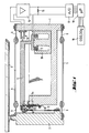
- Fig. 1 the weighing system of the electronic scale is shown in section and the associated electronics as a block diagram.
- the housing of the electronic scale has been left out for the sake of clarity.
- the weighing system consists of a system carrier 1 to which a load receiver 2 is fastened in a vertical direction by means of two links 4 and 5 with the articulation points 6.
- the load receiver 2 transmits the force corresponding to the mass of the goods to be weighed on the weighing pan 3 via a coupling element 9 to the load arm of the transmission lever 7.
- the transmission lever 7 is supported on the system carrier 1 by a cross spring joint 8.
- a coil body with a coil 11 is fastened to the compensation arm of the transmission lever 7.
- the coil 11 is located in the air gap of a permanent magnet system 10 and generates the compensation force.
- the size of the compensation current through the coil 11 is controlled in a known manner by a position sensor 16 and a control amplifier 14 so that there is a balance between the weight of the weighing sample and the electromagnetically generated compensation force.
- the compensation current generates a measuring voltage at a measuring resistor 15, which is fed to an analog / digital converter 17.
- the digitized result is taken over by a digital signal processing unit 18 and displayed digitally in the display 19. -
- the weighing system in FIG. 1 has two springs 12 for astasis, only one of which can be seen in FIG. 1.
- the springs 12 are fixed on the one hand to the transmission lever 7 above the pivot point of the cross spring joint 8 and on the other hand to a projection 13 of the system carrier 1 below the pivot point of the cross spring joint 8.
- the line of action of the springs 12 is in the desired position of the transmission lever 7 exactly through the pivot point of the cross spring joint 8 (see Fig. 1a), so that the springs 12 do not exert any torque on the transmission lever 7 in this position, so do not influence the weighing result.
- the arrangement of the two springs 12 is shown again in a side view of the end face of the transmission lever 7.
- the transmission lever 7 which is connected to the system carrier 1 by means of a cross spring joint consisting of a total of 4 springs 8 (two vertical and two horizontal).
- the coupling element 9 is only indicated with its upper area.
- the two springs 12 for Astastechnik are attached to the transmission lever 7 so that their force application point is above the pivot point, which is given by the cross spring joint 8, on the other hand, they are attached to a projection 13 on the system carrier 1.
- a second embodiment of the weighing system of the electronic scale is shown in plan view in FIG. 3.
- the parallel guide consists of a single block 20, which includes both the system carrier 21, the load receiver 22 and the link 23 with the thin points 24.
- a magnet 28, an optical position sensor 30/31 and, via two springs 26, the transmission lever 25 are fastened to the system carrier 21.
- the power transmission from the load receiver 22 with the mounting cone 22 ⁇ for the (not shown) weighing pan takes place via a coupling element 27, which is attached on the one hand to a lower projection 22 'of the load receiver 22 and on the other hand on the transmission lever 25.
- the transmission lever 25 carries on its longer lever arm again a coil 29 for electromagnetic force compensation. -
- This weighing system is so far known from DE-OS 34 22 042, so that a more detailed description can be omitted here.
- this weighing system now has two springs in the form of a wire 32, as can best be seen from the associated side view in FIG. 4.
- the two wires 32 are so thin that they act as springs. They are attached to the transmission lever 25 by means of clamping plates 33 and to the system carrier 21 by means of clamping plates 34.
- the mode of operation corresponds to the mode of operation of the springs 12 already explained above.
- FIG. 5 A third embodiment of the weighing system of the electronic balance is shown in FIG. 5, where only the parts essential to the invention are shown in a side view.
- the transmission lever 42 is again connected to the system carrier 41 via vertical springs 44.
- the coupling element 43 is only drawn in its upper area.
- the transmission lever 42 has two lateral projections 45, over the ends 46 of which a tension wire 47 is guided.
- both suspension components can be approximately the same size or one or the other component can predominate.
- FIG. 5 A further detail is indicated in FIG. 5: the lateral projections 45 on the transmission lever 42 and the tensioning wire 47 are surrounded by metal walls 50 which protrude from the system carrier 41.
- the parts 45 and 47 of the aeration spring can be thermally coupled to the system carrier, so that as little temperature differences as possible can occur.
- a static temperature coefficient of the force of the astasis spring can also be brought close to zero or brought close to the temperature coefficient of the spring constant of the cross-spring joint and the parallel link guide. As a result, the influence of temperature changes and the influence of temperature gradients can largely be eliminated.
- a band can of course also be used in the above exemplary embodiments.
- a band or a wire can be used as the spring.
- the two springs instead of the two springs, only one spring arranged in the middle can be used.
- the simple attachment of the spring (s) shown using grub screws or clamping pieces more complex ones can also be used Fastening structures that allow adjustment of the tensile force and the lateral position can be used.
- standing leaf springs are always shown as pivot bearings for the transmission lever, and these leaf springs are subjected to pressure / buckling by the astasis springs.
- hanging leaf springs can also be used as pivot bearings for the transmission lever, which are subjected to tension by the astasis springs.
- All of these variants can easily be designed by any person skilled in the art, so that a detailed description can be dispensed with here.
- the design according to the invention can also be applied analogously to electronic weighing systems with several levers coupled in series.
Landscapes
- Physics & Mathematics (AREA)
- General Physics & Mathematics (AREA)
- Electromagnetism (AREA)
- Springs (AREA)
- Transmission Devices (AREA)
- Measurement Of Force In General (AREA)
- Manipulator (AREA)
Description
- Die Erfindung bezieht sich auf eine elektronische Waage gemäß dem Oberbegriff des Anspruches 1. Elektronische Waagen dieser Art sind allgemein bekannt z.B. durch die DE-OS 36 39 521, bei der die Biegefeder als Kreuzbandgelenk ausgebildet ist. In der DE-Ul-85 16 448 ist das Kreuzbandgelenk einer solchen Waage beschrieben, bei dem ein geringes rücktreibendes Moment angestrebt ist. Aus der EP-291 258-A2 ist eine Waage mit Biegefeder am Übersetzungshebel bekannt, die Bestandteil einer gefrästen Parallelführung sind.
- Aus der DE-PS 1 238 229 ist es weiterhin bekannt, bei einer mechanischen Waage mit Parallelführung und Hebel eine Feder mit horizontaler Wirkungslinie am Waagschalenträger angreifen zu lassen. Die Übertragung dieser Anordnung auf eine elektronische Waage ist insofern nachteilig, als die horizontale Feder deutlich länger als die Lenker der Parallelführung sein muß, um eine gute Wirksamkeit zu ergeben. Dies würde jedoch die Baugröße der Waage deutlich vergrößern.
- Aufgabe der Erfindung ist es daher, für eine elektronische Waage der eingangs genannten Art eine platzsparende und besonders wirksame Astasierungsmöglichkeit zu schaffen.
- Erfindungsgemäß wird dies durch den kennzeichnenden Teil des Anspruches 1 erreicht.
- Greift die Astasierungsfeder gemäß dem Stand der Technik am parallelgeführten Waagschalenträger an, so beschreibt der Angriffspunkt der Feder einen Kreis mit dem Radius der Lenkerlänge - üblicherweise ca. 50...100 mm. Greift die Astasierungsfeder jedoch erfindungsgemäß am Übersetzungshebel an, so kann der Angriffspunkt der Feder z.B. auf 5 mm an den Hebeldrehpunkt herangebracht werden, wodurch sowohl die Wirksamkeit der Astasierungsfeder wesentlich erhöht wird, als auch die notwendige Baulänge der Feder in gleichem Maße verkürzt wird. Außerdem kann die Wirkungsrichtung der Astasierungsfeder je nach Platzerfordernissen in beliebiger Richtung liegen. Dadurch kann sowohl eine Bauart gewählt werden, in der die Astasierungsfeder waagerecht verläuft - wie in der zitierten DE-PS 1 238 229 -, als auch eine Bauart, in der die Astasierungsfeder senkrecht verläuft. Die letztere Bauform hat den Vorteil, daß sie auch dann einsetzbar ist, wenn die Lagerung des Übersetzungshebels am Systemträger nur aus einer oder mehreren senkrecht stehenden Blattfedern besteht.
- Die Astasierungsfeder besteht in einer vorteilhaften Ausgestaltung aus einem Draht oder Band. Dies erfordert nur einen geringen Platzaufwand für die Feder. Dabei wird die Erkenntnis ausgenutzt, daß der große mögliche Federweg einer üblichen Schraubenfeder für eine Astasierungsfeder gar nicht nötig ist, daß also auch eine Federbauform benutzt werden kann, die ihre volle Zugkraft schon bei einer geringen Längenänderung erreicht.
- In einer anderen vorteilhaften Ausgestaltung besteht die Astasierungsfeder aus einem seitlich auskragenden elastischen Vorsprung am Übersetzungshebel und dieser seitlich auskragende elastische Vorsprung ist über einen Draht oder ein Band mit dem Systemträger verbunden. Auch dies ergibt eine sehr kompakte Bauweise.
- Selbstverständlich können diese beiden Ausgestaltungen auch insofern miteinander kombiniert werden, daß sowohl der seitlich auskragende Vorsprung als auch der Draht bzw. das Band so dimensioniert sind, daß sie zur Nachgiebigkeit beitragen und somit als Teil der Astasierungsfeder wirken.
- Um Temperaturgradienten zwischen der Astasierungsfeder und dem Systemträger zu vermeiden, wird die Astasierungsfeder vorteilhafterweise wenigstens teilweise in einem Hohlraum untergebracht, dessen Wände mit dem Systemträger verbunden sind.
- Die Erfindung wird im folgenden anhand der schematischen Figuren beschrieben. Dabei zeigt:
- Fig. 1 das Wägesystem der elektronischen Waage im Schnitt und die zugehörige Elektronik als Blockschaltbild,
- Fig. 1a eine Detailvergrößerung aus Fig. 1 gem. Ausschnitt Ia,
- Fig. 2 eine Seitenansicht des Systemträgers und der Lagerung des Übersetzungshebels aus Fig. 1,
- Fig. 3 eine zweite Ausgestaltung des Wägesystems der elektronischen Waage in Draufsicht,
- Fig. 4 eine Seitenansicht des Systemträgers und der Lagerung des Übersetzungshebels aus Fig. 3 und
- Fig. 5 eine dritte Ausgestaltung des Wägesystems der elektronischen Waage in Seitenansicht auf den Systemträger und die Lagerung des Übersetzungshebels.
- In Fig. 1 ist das Wägesystem der elektronischen Waage im Schnitt dargestellt und die zugehörige Elektronik als Blockschaltbild. Das Gehäuse der elektronischen Waage ist der Übersichtlichkeit halber weggelassen. Das Wägesystem besteht aus einem Systemträger 1, an dem über zwei Lenker 4 und 5 mit den Gelenkstellen 6 ein Lastaufnehmer 2 in senkrechter Richtung beweglich befestigt ist. Der Lastaufnehmer 2 überträgt die der Masse des Wägegutes auf der Waagschale 3 entsprechende Kraft über ein Koppelelement 9 auf den Lastarm des Übersetzungshebels 7. Der Übersetzungshebel 7 ist durch ein Kreuzfedergelenk 8 am Systemträger 1 gelagert. Am Kompensationsarm des Übersetzungshebels 7 ist ein Spulenkörper mit einer Spule 11 befestigt. Die Spule 11 befindet sich im Luftspalt eines Permanentmagnetsystems 10 und erzeugt die Kompensationskraft. Die Größe des Kompensationsstromes durch die Spule 11 wird dabei in bekannter Weise durch einen Lagensensor 16 und einen Regelverstärker 14 so geregelt, daß Gleichgewicht zwischen dem Gewicht des Wägegutes und der elektromagnetisch erzeugten Kompensationskraft herrscht. Der Kompensationsstrom erzeugt an einem Meßwiderstand 15 eine Meßspannung, die einem Analog/Digital-Wandler 17 zugeführt wird. Das digitalisierte Ergebnis wird von einer digitalen Signalverarbeitungseinheit 18 übernommen und in der Anzeige 19 digital angezeigt. - Diese Teile des Wägesystems der elektronischen Waage sind allgemein bekannt und im vorstehenden daher nur ganz kurz beschrieben.
- Weiter weist das Wägesystem in Fig. 1 zur Astasierung zwei Federn 12 auf, von denen in Fig. 1 nur eine erkennbar ist. Die Federn 12 sind einerseits am Übersetzungshebel 7 oberhalb des Drehpunktes des Kreuzfedergelenkes 8 befestigt und andererseits an einem Vorsprung 13 des Systemträgers 1 unterhalb des Drehpunktes des Kreuzfedergelenkes 8. Die Wirkungslinie der Federn 12 geht in der Soll-Lage des Übersetzungshebels 7 genau durch den Drehpunkt des Kreuzfedergelenkes 8 (siehe Fig. 1a), so daß in dieser Lage die Federn 12 kein Drehmoment auf den Übersetzungshebel 7 ausüben, das Wägeergebnis also nicht beeinflussen. Nur wenn der Übersetzungssetzungshebel 7 aus seiner Soll-Lage ausgelenkt wird, führt die Zugkraft der Federn 12 zu einem Drehmoment auf den Übersetzungshebel 7, wobei die Wirkrichtung dieses Drehmomentes so ist, daß es die Auslenkung aus der Soll-Lage zu vergrößern sucht. Damit wirkt das Drehmoment der Federn 12 genau entgegengesetzt zum Drehmoment aus den Federn des Kreuzfedergelenkes 8, das den Übersetzungshebel 7 jeweils zurück zur Soll-Lage zu drehen versucht. Bei richtiger Dimensionierung der Kraft der Federn 12 heben sich beide Drehmomente gerade auf und der Übersetzungshebel 7 läßt sich drehmomentfrei bewegen, ist also astasiert. Selbstverständlich gilt dies nur für einen beschränkten Winkelbereich. In gleicher Weise kann durch die Federn 12 nicht nur das rücktreibende Drehmoment des Kreuzfedergelenkes 8 sondern auch das zusätzliche rücktreibende Drehmoment der Parallelführung aus den Lenkern 4 und 5 ganz oder teilweise aufgehoben werden.
- In Fig. 2 ist die Anordnung der beiden Federn 12 nochmal in einer Seitenansicht auf die Stirnfläche des Übersetzungshebels 7 gezeigt. Man erkennt den Übersetzungshebel 7, der über ein Kreuzfedergelenk aus insgesamt 4 Federn 8 (zwei senkrechte und zwei waagerechte) mit dem Systemträger 1 verbunden ist. Das Koppelelement 9 ist nur mit seinem oberen Bereich angedeutet. Die beiden Federn 12 zur Astasierung sind zum einen so am Übersetzungshebel 7 befestigt, daß ihr Kraftangriffspunkt oberhalb des Drehpunktes liegt, der durch das Kreuzfedergelenk 8 gegeben ist, zum anderen sind sie an einem Vorsprung 13 am Systemträger 1 befestigt.
- Eine zweite Ausgestaltung des Wägesystems der elektronischen Waage ist in Fig. 3 in Draufsicht gezeigt. Die Parallelführung besteht aus einem einzigen Block 20, der sowohl den Systemträger 21, den Lastaufnehmer 22 als auch die Lenker 23 mit den Dünnstellen 24 umfaßt. Am Systemträger 21 ist ein Magnet 28, ein optischer Lagensensor 30/31 und über zwei Federn 26 der Übersetzungshebel 25 befestigt. Die Kraftübertragung vom Lastaufnehmer 22 mit dem Befestigungskonus 22˝ für die (nicht gezeichnete) Waagschale erfolgt über ein Koppelelement 27, das einerseits an einem unteren Vorsprung 22′ des Lastaufnehmers 22 befestigt ist und andererseits am Übersetzungshebel 25. Der Übersetzungshebel 25 trägt an seinem längeren Hebelarm wieder eine Spule 29 für die elektromagnetische Kraftkompensation. - Dieses Wägesystem ist soweit aus der DE-OS 34 22 042 bekannt, so daß hier auf eine detailliertere Beschreibung verzichtet werden kann.
- Dieses Wägesystem weist nun zusätzlich zur Astasierung zwei Federn in Form je eines Drahtes 32 auf, wie am besten aus der zugehörigen Seitenansicht in Fig. 4 zu erkennen ist. Die beiden Drähte 32 sind so dünn, daß sie als Federn wirken. Sie sind durch Klemmplättchen 33 am Übersetzungshebel 25 befestigt und durch Klemmplättchen 34 am Systemträger 21. Die Wirkungsweise entspricht der bereits weiter oben erläuterten Wirkungsweise der Federn 12.
- Eine dritte Ausgestaltung des Wägesystems der elektronischen Waage zeigt Fig. 5, wobei dort nur die erfindungswesentlichen Teile in Seitenansicht dargestellt sind. Der Übersetzungshebel 42 ist wieder über senkrechte Federn 44 mit dem Systemträger 41 verbunden. Das Koppelelement 43 ist nur in seinem oberen Bereich gezeichnet. Zur Astasierung weist der Übersetzungshebel 42 zwei seitliche Vorsprünge 45 auf, über deren Enden 46 ein Spanndraht 47 geführt ist.
- Die Enden des Spanndrahtes 47 sind mit zwei Klemmplatten 48 am Systemträger 41 befestigt. Sowohl die seitlichen Vorsprünge 45 als auch der Spanndraht 47 sind elastisch und wirken damit als Teil der Astasierungsfeder. Je nach Dimensionierung der seitlichen Vorsprünge 45 und je nach Durchmesser des Spanndrahtes 47 können beide Federungsanteile etwa gleich groß sein oder es kann der eine oder der andere Anteil überwiegen.
- In Fig. 5 ist ein weiteres Detail angedeutet: Die seitlichen Vorsprünge 45 am Übersetzungshebel 42 und der Spanndraht 47 sind von Metallwänden 50 umgeben, die vom Systemträger 41 hochragen. Durch nicht gezeichnete vordere Abschlußkappen konnen so die Teile 45 und 47 der Astasierungsfeder thermisch an den Systemträger gekoppelt werden, damit möglichst keine Temperaturunterschiede auftreten können. Durch richtige Wahl der Werkstoffe der einzelnen Komponenten kann auch ein statischer Temperaturkoeffizient der Kraft der Astasierungsfeder nahe an Null gebracht werden bzw. nahe an den Temperaturkoeffizienten der Federkonstante des Kreuzfedergelenkes und der Lenkerparallelführung herangebracht werden. Dadurch kann der Einfluß von Temperaturänderungen und der Einfluß von Temperaturgradienten weitgehend ausgeschaltet werden.
- Statt des Drahtes kann in den vorstehenden Ausführungsbeispielen selbstverständlich auch ein Band benutzt werden. Genauso kann im Ausführungsbeispiel nach den Figuren 1 und 2 statt der gezeichneten Schraubenfeder ein Band oder ein Draht als Feder benutzt werden. Statt der zwei Federn kann jeweils nur eine, mittig angeordnete Feder benutzt werden. Statt der gezeichneten einfachen Befestigung der Feder(n) durch Madenschrauben bzw. Klemmstücke können auch aufwendigere Befestigungskonstruktionen, die eine Justierung der Zugkraft und der seitlichen Lage erlauben, eingesetzt werden. In den gezeigten Ausführungsbeispielen sind immer stehende Blattfedern als Drehlager für den Übersetzungshebel gezeigt und diese Blattfedern werden durch die Astasierungsfedern auf Druck/Knickung beansprucht. Genauso können natürlich auch hängende Blattfedern als Drehlager für den Übersetzungshebel benutzt werden, die durch die Astasierungsfedern auf Zug beansprucht werden. - Alle diese Varianten kann jeder Fachmann leicht selbst entwerfen, so daß auf eine detaillierte Beschreibung hier verzichtet werden kann.
- Weiterhin ist die erfindungsmäßige Ausführung auch auf elektronische Wägesysteme mit mehreren hintereinandergekoppelten Hebeln sinngemäß übertragbar.
Claims (6)
Applications Claiming Priority (2)
| Application Number | Priority Date | Filing Date | Title |
|---|---|---|---|
| DE3829637A DE3829637C1 (de) | 1988-09-01 | 1988-09-01 | |
| DE3829637 | 1988-09-01 |
Publications (3)
| Publication Number | Publication Date |
|---|---|
| EP0359978A2 EP0359978A2 (de) | 1990-03-28 |
| EP0359978A3 EP0359978A3 (en) | 1990-04-04 |
| EP0359978B1 true EP0359978B1 (de) | 1992-02-26 |
Family
ID=6362036
Family Applications (1)
| Application Number | Title | Priority Date | Filing Date |
|---|---|---|---|
| EP89114785A Expired - Lifetime EP0359978B1 (de) | 1988-09-01 | 1989-08-09 | Elektronische Waage |
Country Status (5)
| Country | Link |
|---|---|
| US (1) | US4930588A (de) |
| EP (1) | EP0359978B1 (de) |
| JP (1) | JPH02107926A (de) |
| DE (1) | DE3829637C1 (de) |
| ES (1) | ES2030247T3 (de) |
Cited By (3)
| Publication number | Priority date | Publication date | Assignee | Title |
|---|---|---|---|---|
| DE102023005499A1 (de) * | 2023-11-20 | 2025-05-22 | Sartorius Lab Instruments Gmbh & Co. Kg | Wägesystem mit Astasierungshebel |
| DE102023132262A1 (de) * | 2023-11-20 | 2025-05-22 | Sartorius Lab Instruments Gmbh & Co. Kg | Wägesystem mit Astasierungshebel |
| DE102025100938B3 (de) * | 2025-01-13 | 2026-01-22 | Sartorius Lab Instruments Gmbh & Co. Kg | Wägesystem mit Astasierungshebel |
Families Citing this family (9)
| Publication number | Priority date | Publication date | Assignee | Title |
|---|---|---|---|---|
| CH677534A5 (de) * | 1989-05-09 | 1991-05-31 | Mettler Toledo Ag | |
| DE10202951A1 (de) * | 2002-01-26 | 2003-08-21 | Bizerba Gmbh & Co Kg | Kraftmesszelle |
| EP1898193B1 (de) * | 2006-09-05 | 2016-06-01 | Mettler-Toledo GmbH | Kraftmessvorrichtung und Referenzeinheit |
| PL2607866T3 (pl) * | 2011-12-22 | 2015-05-29 | Mettler Toledo Gmbh | Ogniwo obciążnikowe według zasady elektromagnetycznej kompensacji siły z optoelektronicznym czujnikiem pozycji |
| EP2784453B1 (de) * | 2013-03-28 | 2018-10-10 | Mettler-Toledo GmbH | Digitale Wägezellenlinearisierung |
| US10132672B2 (en) | 2013-03-28 | 2018-11-20 | Mettler-Toledo Gmbh | Digital linearization in a weighing cell |
| CN109870226B (zh) * | 2017-12-04 | 2025-02-21 | 梅特勒-托利多仪器(上海)有限公司 | 称重传感器及其杠杆 |
| DE102018133563B4 (de) * | 2018-12-21 | 2020-10-22 | Wipotec Gmbh | Waage mit Überlastdiagnose |
| WO2021067213A1 (en) * | 2019-09-30 | 2021-04-08 | Carrier Corporation | Self reporting fire suppressant tank configuration |
Family Cites Families (12)
| Publication number | Priority date | Publication date | Assignee | Title |
|---|---|---|---|---|
| US3080936A (en) * | 1957-12-20 | 1963-03-12 | Foils Packaging Corp | Weighing scale |
| DE1238229B (de) * | 1964-10-02 | 1967-04-06 | Mepag A G | Justiervorrichtung fuer eine oberschalige Praezisionswaage |
| US3955638A (en) * | 1975-03-05 | 1976-05-11 | Voland Corporation | Precision balance |
| US4113040A (en) * | 1977-06-17 | 1978-09-12 | Pitney-Bowes, Inc. | Null transducer for an analytical balance |
| JPS57111419A (en) * | 1980-12-29 | 1982-07-10 | Shimadzu Corp | Electronic even balance |
| CH652207A5 (de) * | 1981-09-02 | 1985-10-31 | Mettler Instrumente Ag | Biegekoppel fuer waagen. |
| DE3422042A1 (de) * | 1984-06-14 | 1985-12-19 | Sartorius GmbH, 3400 Göttingen | Oberschalige elektronische hebelwaage |
| EP0195875B1 (de) * | 1985-03-25 | 1989-02-01 | K-TRON Patent AG | Massen- und Kraftmessgerät |
| DE8516448U1 (de) * | 1985-06-05 | 1985-08-08 | Sartorius GmbH, 3400 Göttingen | Kreuzbandgelenk für eine elektronische Waage |
| CH670703A5 (de) * | 1986-06-06 | 1989-06-30 | Mettler Instrumente Ag | |
| DE3639521C2 (de) * | 1986-11-20 | 1994-03-17 | Sartorius Gmbh | Elektrische Waage |
| US4799561A (en) * | 1987-05-09 | 1989-01-24 | Shimadzu Corporation | Electronic balance |
-
1988
- 1988-09-01 DE DE3829637A patent/DE3829637C1/de not_active Expired - Lifetime
-
1989
- 1989-08-09 ES ES198989114785T patent/ES2030247T3/es not_active Expired - Lifetime
- 1989-08-09 EP EP89114785A patent/EP0359978B1/de not_active Expired - Lifetime
- 1989-08-28 US US07/398,958 patent/US4930588A/en not_active Expired - Fee Related
- 1989-09-01 JP JP1224752A patent/JPH02107926A/ja active Pending
Cited By (6)
| Publication number | Priority date | Publication date | Assignee | Title |
|---|---|---|---|---|
| DE102023005499A1 (de) * | 2023-11-20 | 2025-05-22 | Sartorius Lab Instruments Gmbh & Co. Kg | Wägesystem mit Astasierungshebel |
| DE102023132262A1 (de) * | 2023-11-20 | 2025-05-22 | Sartorius Lab Instruments Gmbh & Co. Kg | Wägesystem mit Astasierungshebel |
| WO2025108617A1 (de) | 2023-11-20 | 2025-05-30 | Sartorius Lab Instruments Gmbh & Co. Kg | Wägesystem mit astasierungshebel |
| DE102023132262B4 (de) * | 2023-11-20 | 2025-06-05 | Sartorius Lab Instruments Gmbh & Co. Kg | Wägesystem mit Astasierungshebel |
| DE102023005499B4 (de) * | 2023-11-20 | 2025-06-05 | Sartorius Lab Instruments Gmbh & Co. Kg | Wägesystem mit Astasierungshebel |
| DE102025100938B3 (de) * | 2025-01-13 | 2026-01-22 | Sartorius Lab Instruments Gmbh & Co. Kg | Wägesystem mit Astasierungshebel |
Also Published As
| Publication number | Publication date |
|---|---|
| JPH02107926A (ja) | 1990-04-19 |
| DE3829637C1 (de) | 1990-04-12 |
| EP0359978A2 (de) | 1990-03-28 |
| ES2030247T3 (es) | 1992-10-16 |
| US4930588A (en) | 1990-06-05 |
| EP0359978A3 (en) | 1990-04-04 |
Similar Documents
| Publication | Publication Date | Title |
|---|---|---|
| EP0359978B1 (de) | Elektronische Waage | |
| DE3710997C1 (de) | Oberschalige elektronische Waage mit Ecklasteinstellung | |
| DE2556428C3 (de) | Wägevorrichtung | |
| DE10054847C2 (de) | Wägeaufnehmer mit Justiergewicht | |
| DE3316292C2 (de) | ||
| DE2254633A1 (de) | Waage, insbesondere analysenwaage | |
| DE69317085T2 (de) | Wägezelle mit horizontaler Saite und vertikaler Koppel | |
| DE2219727B2 (de) | Kraftmesser | |
| CH469973A (de) | Elektrischer Massenmesser | |
| DE2246500C2 (de) | Kraft- oder Längenmessgerät | |
| DE8909360U1 (de) | Elektronische Waage | |
| DE19502694C1 (de) | Elektronische Waage mit Ecklastsensor | |
| DE3218943C2 (de) | ||
| DE3144260C2 (de) | ||
| DE2919227C2 (de) | Elektromagnetisch kraftkompensierende Präzisionswaage | |
| DE2316862C2 (de) | Saitenmeßgerät | |
| DE4239517C1 (de) | Elektronische Waage mit Übersetzungshebel | |
| DE3724829A1 (de) | Vorrichtung zur messung der kettfadenspannung | |
| DE7828439U1 (de) | Elektromagnetisch kompensierende praezisionswaage | |
| DE9103487U1 (de) | Oberschalige elektronische Waage mit Kalibriergewichtsschaltung | |
| DE843606C (de) | Drehfederwaage | |
| CH618509A5 (en) | Parallel guide, especially for top-pan balances | |
| DE2335779C3 (de) | Mechanische Wägevorrichtung | |
| DE2705251C2 (de) | Temperaturkompensationsvorrichtung an Neigungspendelwaagen | |
| CH533296A (de) | Kraftmesser |
Legal Events
| Date | Code | Title | Description |
|---|---|---|---|
| PUAI | Public reference made under article 153(3) epc to a published international application that has entered the european phase |
Free format text: ORIGINAL CODE: 0009012 |
|
| PUAL | Search report despatched |
Free format text: ORIGINAL CODE: 0009013 |
|
| AK | Designated contracting states |
Kind code of ref document: A2 Designated state(s): CH ES FR GB IT LI |
|
| AK | Designated contracting states |
Kind code of ref document: A3 Designated state(s): CH ES FR GB IT LI |
|
| 17P | Request for examination filed |
Effective date: 19900224 |
|
| 17Q | First examination report despatched |
Effective date: 19910228 |
|
| ITF | It: translation for a ep patent filed | ||
| RAP1 | Party data changed (applicant data changed or rights of an application transferred) |
Owner name: SARTORIUS AG |
|
| GRAA | (expected) grant |
Free format text: ORIGINAL CODE: 0009210 |
|
| AK | Designated contracting states |
Kind code of ref document: B1 Designated state(s): CH ES FR GB IT LI |
|
| ET | Fr: translation filed | ||
| GBT | Gb: translation of ep patent filed (gb section 77(6)(a)/1977) | ||
| REG | Reference to a national code |
Ref country code: ES Ref legal event code: FG2A Ref document number: 2030247 Country of ref document: ES Kind code of ref document: T3 |
|
| PLBE | No opposition filed within time limit |
Free format text: ORIGINAL CODE: 0009261 |
|
| STAA | Information on the status of an ep patent application or granted ep patent |
Free format text: STATUS: NO OPPOSITION FILED WITHIN TIME LIMIT |
|
| 26N | No opposition filed | ||
| PGFP | Annual fee paid to national office [announced via postgrant information from national office to epo] |
Ref country code: CH Payment date: 19950629 Year of fee payment: 7 |
|
| PGFP | Annual fee paid to national office [announced via postgrant information from national office to epo] |
Ref country code: GB Payment date: 19950811 Year of fee payment: 7 |
|
| PGFP | Annual fee paid to national office [announced via postgrant information from national office to epo] |
Ref country code: ES Payment date: 19950821 Year of fee payment: 7 |
|
| PGFP | Annual fee paid to national office [announced via postgrant information from national office to epo] |
Ref country code: FR Payment date: 19950831 Year of fee payment: 7 |
|
| PG25 | Lapsed in a contracting state [announced via postgrant information from national office to epo] |
Ref country code: GB Effective date: 19960809 |
|
| PG25 | Lapsed in a contracting state [announced via postgrant information from national office to epo] |
Ref country code: ES Free format text: LAPSE BECAUSE OF THE APPLICANT RENOUNCES Effective date: 19960810 |
|
| PG25 | Lapsed in a contracting state [announced via postgrant information from national office to epo] |
Ref country code: LI Effective date: 19960831 Ref country code: CH Effective date: 19960831 |
|
| GBPC | Gb: european patent ceased through non-payment of renewal fee |
Effective date: 19960809 |
|
| REG | Reference to a national code |
Ref country code: CH Ref legal event code: PL |
|
| PG25 | Lapsed in a contracting state [announced via postgrant information from national office to epo] |
Ref country code: FR Effective date: 19970430 |
|
| REG | Reference to a national code |
Ref country code: FR Ref legal event code: ST |
|
| REG | Reference to a national code |
Ref country code: ES Ref legal event code: FD2A Effective date: 19991007 |
|
| PG25 | Lapsed in a contracting state [announced via postgrant information from national office to epo] |
Ref country code: IT Free format text: LAPSE BECAUSE OF NON-PAYMENT OF DUE FEES;WARNING: LAPSES OF ITALIAN PATENTS WITH EFFECTIVE DATE BEFORE 2007 MAY HAVE OCCURRED AT ANY TIME BEFORE 2007. THE CORRECT EFFECTIVE DATE MAY BE DIFFERENT FROM THE ONE RECORDED. Effective date: 20050809 |