EP0359673B1 - Verfahren und Vorrichtung zur Feststellung des neutralen Steuerwinkels eines Fahrzeugslenkrades - Google Patents
Verfahren und Vorrichtung zur Feststellung des neutralen Steuerwinkels eines Fahrzeugslenkrades Download PDFInfo
- Publication number
- EP0359673B1 EP0359673B1 EP89402550A EP89402550A EP0359673B1 EP 0359673 B1 EP0359673 B1 EP 0359673B1 EP 89402550 A EP89402550 A EP 89402550A EP 89402550 A EP89402550 A EP 89402550A EP 0359673 B1 EP0359673 B1 EP 0359673B1
- Authority
- EP
- European Patent Office
- Prior art keywords
- steering angle
- neutral
- vehicle
- steering
- value
- Prior art date
- Legal status (The legal status is an assumption and is not a legal conclusion. Google has not performed a legal analysis and makes no representation as to the accuracy of the status listed.)
- Expired - Lifetime
Links
- 230000007935 neutral effect Effects 0.000 title claims description 131
- 238000000034 method Methods 0.000 title claims description 17
- 238000001514 detection method Methods 0.000 claims description 8
- 230000002093 peripheral effect Effects 0.000 claims description 3
- 238000009825 accumulation Methods 0.000 description 3
- 230000004044 response Effects 0.000 description 2
- 238000010586 diagram Methods 0.000 description 1
- 230000008034 disappearance Effects 0.000 description 1
- 230000000694 effects Effects 0.000 description 1
- 230000006870 function Effects 0.000 description 1
- 238000007689 inspection Methods 0.000 description 1
Images




Classifications
-
- B—PERFORMING OPERATIONS; TRANSPORTING
- B62—LAND VEHICLES FOR TRAVELLING OTHERWISE THAN ON RAILS
- B62D—MOTOR VEHICLES; TRAILERS
- B62D15/00—Steering not otherwise provided for
- B62D15/02—Steering position indicators ; Steering position determination; Steering aids
Definitions
- the present invention relates generally to an apparatus and method for detecting a neutral steering angle of a steering wheel system for a vehicle, the neutral steering angle thereof being defined as a steering angle at which the vehicle goes straight, and particularly relates to the apparatus and method for detecting the neutral steering angle for a short period of time immediately after the vehicle has traveled.
- a detection of a neutral steering angle is indispensable for a control of a four wheel steering carried out during a turn of the running vehicle.
- the previously proposed neutral steering angle detecting system includes a microcomputer for receiving a first pulse signal outputted by a steering angle sensor according to a steering angle of a steering wheel and a second pulse signal outputted by a vehicle speed sensor according to a vehicle speed.
- the microcomputer derives a relative steering angle to a steering position of the steering wheel on the basis of the first output signal when an ignition switch of the vehicle is turned on and derives a running distance of the vehicle from the second output signal of the vehicle speed sensor.
- the microcomputer derives an average value and variation width of the steering wheel sampled at a regular interval during the run of the vehicle whenever the vehicle has run at a predetermined reference distance.
- the microcomputer determines that the average value derived together with the variation width is the neutral steering angle.
- the neutral steering angle can always accurately be detected in cases where the turn in the same direction is repeated or where the steering angle is largely deviated from the neutral angle when the ignition switch is turned on.
- the above-described neutral steering angle detecting apparatus cannot determine the average value of the steering wheel as the neutral steering angle when the vehicle does not run straight more than the predetermined distance after the ignition switch is turned on. Therefore, when the ignition switch is turned off and the neutral steering angle detected heretofore disappears, the neutral steering angle is newly updated whenever the ignition switch is turned on. Therefore, a detection accuracy cannot be improved by an accumulation of the detected data.
- Fig. 1 shows a preferred embodiment of a neutral steering angle detecting apparatus according to the present invention.
- a steering angle sensor 1 a vehicle speed sensor 3, and a neutral area sensor 2 are connected to a microcomputer 4.
- the microcomputer 4 includes a CPU 8, a memory 9, an input/output interface 10, and a back-up memory 11.
- the steering angle sensor 1 and neutral proximity steering angle 2 are integrally fitted to a steering shaft 5 as shown in Fig. 2.
- a slitted disc plate 6 is integrally rotatable with the steering shaft 5.
- a photo interrupter 7 is fitted to the slitted disc plate 6 and spaced apart therefrom.
- the slitted disc plate 6 includes a multiple number of steering angle measuring slits 6a aligned along a peripheral edge of an outer periphery thereof, and a single slit 6b installed for detecting a position at which the photo interrupter 7 overlaps therewith in a case when the steering wheel mounted onto the steering shaft 5 is placed in proximity to the neutral steering angle.
- the photo interrupter 7 includes two steering angle measuring light receiving elements 7a, 7b arranged on positions in a radial direction of the slitted disc plate 6 on which the slit 6a is overlapped so as to be spaced apart from each other by a distance which corresponds to an integral number of times of a pitch p of such a slit 6a added or subtracted by 1/4 pitch, a single neutral proximity light receiving element 7c arranged on a position in the radial direction on which it is overlapped with the slit 6b, and a light source (not shown) opposed so as to sandwich the slit disc plate 6 with these light receiving elements 7a, 7b, and 7c.
- the slit 6a is moved between the light receiving elements 7a, 7b and light source on the basis of the slitted disc plate 6 (steering shaft 5). Since two kinds of steering angle pulse signals E1, E2 are outputted having two different phase deviations according to the direction along which the steering wheel is steered as shown in Figs. 3 (a) and 3 (b) from the light receiving elements 7a, 7b, the light source opposing the steering angle measuring slit 6a and steering angle measuring light receiving elements 7a, 7b is functioned as the steering angle sensor 1.
- the slit 6b is rotated between the light receiving element 7c and light source on the basis of the rotation of the slitted disc plate 6.
- the neutral proximity pulse signal E3 as shown in Fig.3 (c) is outputted from the light receiving element 7c. Therefore, the neutral proximity detecting slit 6b and neutral proximity detecting light receiving element 7c the light source opposing the neutral proximity detecting slit 7c function as a neutral proximity sensor 2.
- the vehicle speed sensor 3 includes a magnet connected to a vehicle's speedometer cable and rotatable integrally to the speedometer and a lead switch fixed to the vehicle body and placed in the vicinity to the magnet.
- the vehicle speed pulse signal S whose number corresponds to the running distance on the basis of the rotation of magnet in response to the run of the vehicle.
- the microcomputer 4 includes a Central Processing Unit (CPU) 8, a Memory 9 having a Read Only Memory (ROM) and Random Access Memory (RAM), an interface 10 carrying out input/output of signals, and a back up battery 11 for preventing the disappearance of the memory contents.
- the back up battery 11 maintaines a part of the RAM in the memory 9 in a valid state even though the vehicle ignition switch is turned off.
- the microcomputer 4 receives the power supply when the ignition switch is turned on and inputs the steering angle signals E1 and E2 and neutral proximity signal E3, and vehicle speed signal S via the interface 10.
- the neutral steering angle ⁇ N (n) is derived (provided that n denotes a positive integral number incremented whenever ⁇ N is derived).
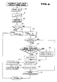
- Fig. 4 shows a program for detecting the steering angle and reproducing the neutral steering angle which is executed whenever it is interrupted by a timer for each predetermined interval ⁇ t which is sufficiently short as compared with a shortest possible steering speed.
- a step 20 the CPU determines whether the microcomputer 4 receives the inputs of the steering angle signals E1 and E2.
- the routine goes to a step 21 when no steering angle signal is received.
- the steering angle ⁇ (t - ⁇ t) derived when the program is previously executed (it is noted that when the program shown in Fig. 4 is initially executed, the steering angle indicates an appropriate value) is set as a present steering angle ⁇ (t).
- a step 22 the microcomputer 4 determines whether the steering angle direction is deviated from a clockwise direction with respect to the direction of phase deviations of these steering angle signals E1 and E2. If the steering direction is not the clockwise direction , i.e., anticlockwise direction, the routine goes to a step 23. In the step 23, the CPU subtracts the steering angle ⁇ of one pitch of the slit 6a from the previously derived steering angle ⁇ (t - ⁇ t).
- the present steering angle ⁇ (t) is set with the above-described steering angle ⁇ added to the previously derived steering angle ⁇ (t - ⁇ t).
- the CPU determines whether the neutral proximity signal E3 is turned on. If it is not turned on, the present program routine is ended. If it is turned on, the steering angle ⁇ (t) indicates that the predetermined angle is in the vicinity to the neutral steering angle, so that the present steering angle ⁇ (t) is set as the neutral proximity steering angle ⁇ c in the step 26. The value of ⁇ c is written into the RAM of the memory 9.
- the CPU determines whether the neutral proximity steering angle ⁇ c has been set in the previous step 26 for the first time, since the ignition switch has been turned on. If it indicates the first value, the CPU reads a final memory value ⁇ M representative of the neutral steering angle ⁇ N (n) stored before the ignition switch has previously been turned off. The CPU determines whether an absolute value of a difference between the neutral steering angle stored value ⁇ M and neutral proximity steering angle ⁇ c derived in the step 26 is less than a predetermined value k (
- the determination in the step 28 is prepared on a fail safe structure base to prevent erroneous determination of the neutral steering angle ⁇ N (n) from a deviation quantity memory value ⁇ R in a case where the relative positional relationship between the neutral steering angle memory value ⁇ M and neutral proximity steering angle ⁇ C is varied and a deviation quantity memory value ⁇ R (as will be described later) becomes unreliable because the steering wheel has been steered during the off state of the ignition switch or a regular inspection of the vehicle has been carried out.
- a predetermined value k which is by nature small to some degree
- the CPU determines that there is a change in the relative positional relationship between ⁇ M and ⁇ C . At this time, The CPU ends the present program routine. In the former case, the CPU determines that the deviation quantity memory value ⁇ R is reliable and goes to a step 29.
- the final memory value ⁇ R is held during the switch being turned off from the RAM of the memory 9 (see below in conjunction with Fig. 5).
- Fig. 5 shows a program routine for detecting the neutral steering angle executed in response to an interrupt command, i.e., executed whenever the vehicle speed pulse signal S from the vehicle speed sensor is turned on (the vehicle has run by a predetermined distance ⁇ l.
- the CPU reads the previously detected steering angle ⁇ (t) written within the RAM.
- the steering angle ⁇ (t) read in the step 30 indicates the data extracted whenever the vehicle has run at a constant distance ⁇ l.
- the CPU adds the above-described predetermined distance ⁇ l to the counter l measuring the running distance.
- the CPU compares the value of the steering angle ⁇ (t) read in the step 30 with maximum value ⁇ max and minimum value ⁇ min stored in the RAM. If the value of ⁇ (t) is larger than the value ⁇ max , the CPU updates the value of ⁇ max . If the value of ⁇ (t) is less than ⁇ min , the CPU updates the value of ⁇ min , respectively.
- the CPU determines whether the running distance l is smaller than the previously set reference distance L (l ⁇ L). If l ⁇ L, the routine goes to a step 34. After the previous value of ⁇ (t) read in step 30 is added to the sum ⁇ SUM of the steering angle in the step 34, if l ⁇ L. the program is ended (with step 37). If not l ⁇ L, i.e. , the vehicle has run by the reference distance L, the routine goes to a step 35.
- ⁇ SUM which is a total sum of the steering angle during the run of the vehicle along the reference distance L is divided by the data number of the steering angle (L/ ⁇ l) to calculate an average value of the steering angle ⁇ AVE .
- the CPU calculates a difference between the maximum value ⁇ max and minimum value ⁇ min of the steering angle during the run of the reference distance L so as to derive a variation width.
- the CPU determines whether its variation width falls within the reference width ⁇ .
- the determination of the step 36 is carried out to derive the neutral steering angle ⁇ N (n) from the data of the steering angle ⁇ t measured during the run only if the probability that the run during the reference distance L is extremely high. If the variation width falls within the reference width ⁇ ( ⁇ max - ⁇ min ⁇ ⁇ ) previously set as a range to adjust the steering angle in order to maintain the running road usually when the vehicle runs straight. The routine goes to a step 37 when the CPU determines that the probability that the run by the reference distance L was straight is extremely high.
- a step 37 the CPU determines that the neutral steering angle ⁇ N (n) was derived more than once after the operation start of the memory 9.
- the routine goes to a step 38, in which , the average value ⁇ AVE of the steering angle derived in the step 35 is set as the neutral steering angle ⁇ N (1).
- the routine goes to a step 39 in a case where the average value ⁇ AVE is already derived more than once.
- step 38 is executed only immediately after the vehicle in which the neutral steering position detecting apparatus according to the present invention has been installed and only when the CPU executes all of the contents of the RAM of the memory 9 has disappeared due to the life of the back up battery 11.
- the derived deviation quantity ⁇ Nr is updated with the value of ⁇ R written during the previous execution of the program as the memory value ⁇ R and is written within the RAM, 40b, to which the back up battery 11 is connected in the step 38, or in the step 39.
- the CPU replaces the neutral steering angle ⁇ N derived in the step 38, or step 39 with the previously written value of ⁇ M as the memory value ⁇ M within the RAM, 40a, to which the back up battery 11 is connected in order to be used for the processing in the previously mentioned step 28.
- the ignition switch is turned off and the final values of both the deviation quantity ⁇ Nr and neutral steering angle ⁇ N derived during the previous on state , is held within the RAM as the memory value ⁇ R and memory value ⁇ M .
- the CPU does not derive the neutral steering angle ⁇ N and skips the steps 37 through 40 described above since the probability that the run of the reference distance L was a turning run in cases where the variation width does not fall within the reference width ⁇ is extremely high.
- step 41 all of the values of l, ⁇ SUM , ⁇ max , and ⁇ min are cleared in order to prepare the calculation processing of the steering angle data during the run of the subsequent reference distance L. Thereafter, this program is ended.
- the reference width ⁇ may be updated with the value of the variation width ( ⁇ max - ⁇ min ) derived in the step 36 used to update the reference width ⁇ .
- the variation width i.e., the reference width ⁇ becomes gradually narrower corresponding to the actual steering situation, the detection accuracy of the neutral steering angle becomes improved as the total running distance becomes longer.
- Fig. 6 shows characteristic graphs of change patterns of the steering angle ⁇ (t) and the neutral steering angle ⁇ N (n) immediately after the ignition switch has been turned on, as a specific example of the operating state of the above-described state.
- a solid line A denotes the change pattern of the neutral steering angle ⁇ t immediately after the ignition switch has been turned on
- a solid line B denotes the change pattern of the neutral steering angle ⁇ N in the preferred embodiment
- a solid line C denotes the change pattern of the neutral steering angle in the previously proposed apparatus.
- a dot-dot,-and dash line D denotes a real steering angle.
- the instantaneous steering angle ⁇ (t) is set as the neutral proximity steering angle ⁇ C at a time t3 at which the steering angle becomes a predetermined angle placed in the vicinity to the neutral angle range ⁇ N (n) and the neutral steering angle ⁇ N is reproduced from the value ⁇ c and the stored deviation quantity ⁇ R . Therefore, the value of the neutral steering angle ⁇ N (n) is accurate and the neutral steering angle ⁇ N (n) is speedily derived when the steering angle becomes in the proximity to the neutral position.
- the reference width ⁇ is narrowed as the running distance becomes long.
- the neutral steering angle at which the accuracy becomes higher is used after the ignition switch has again turned on.
- the accumulation of the data can improve the detection accuracy of the neutral steering angle.
- the neutral proximity detecting slit 6c is installed having a relatively wide width such that the neutral proximity detecting light receiving element 7c is inserted in the slitted disc plate 6 described in the first preferred embodiment between both end edges in the peripheral direction of the slit at the neutral steering angle in place of the neutral proximity detecting slit 6b.
- the steering angles ⁇ (t) at both end edges of the slit 6c are set as the neutral proximity steering angles ⁇ a and ⁇ b .
- the deviation quantity between these ⁇ a and ⁇ b and the neutral steering angle ⁇ N (n) is stored in the RAM and stored during the turning off of the ignition switch.
- Fig. 8 shows characteristic graphs of the change patterns of the operations of the above-described apparatus.
- the same reference numerals denote the corresponding elements.
- the neutral proximity steering angle ⁇ N (n) is reproduced at a time t3 at which the steering angle indicates the neutral proximity steering angle ⁇ a or ⁇ b largely remote from the neutral steering angle than that in the first preferred embodiment. Therefore, at a time when the ignition switch has been turned on, e.g., at a time when the ignition switch has been turned on, the steering wheel is steered to some degree by means of, e.g., a steering lock mechanism at a time when the ignition switch has been turned on.
- the neutral steering angle can be derived at an earlier than the first preferred embodiment. In the first preferred embodiment, the effect that the neutral steering angle can be derived at an earlier stage even when the steering angle is returned to the neutral steering angle from either of both left and right directions.
- the neutral proximity sensor may be installed independently of the steering angle sensor.
- the back up power supply for the memory may directly be received from the vehicle battery in place of via the ignition switch.
- the neutral steering angle detecting apparatus As described hereinabove, in the neutral steering angle detecting apparatus according to the present invention, the final value of the deviation quantity between the predetermined steering angle in the vicinity to the neutral steering angle and the neutral steering angle is stored during the turning off of the ignition switch. After the ignition switch has been turned on, the steering angle initially reaches the predetermined steering angle. At this time, the neutral steering angle is reproduced from the steering angle at that time and from the final value of the above-described deviation quantity. The neutral steering angle is detected for an extremely short time. Furthermore, the neutral steering angle data can be used before the ignition switch has been turned off so that the detection accuracy by the accumulation of the data can be improved.
Landscapes
- Engineering & Computer Science (AREA)
- Chemical & Material Sciences (AREA)
- Combustion & Propulsion (AREA)
- Transportation (AREA)
- Mechanical Engineering (AREA)
- Length Measuring Devices With Unspecified Measuring Means (AREA)
- Steering Controls (AREA)
Claims (13)
- Ein Verfahren zur Ermittlung eines neutralen Steuerwinkels (ϑN(n)) eines Lenkrades eines Fahrzeugs, z.B. mit zwei oder vier lenkbaren Leiträdern, mit den folgenden Schritten :a) Ermittlung eines Steuerwinkels (E1; ϑ(t)) des Lenkrades mittels eines Steuerwinkelgebers (1) mit einer mit einer Lenkwelle (5) des Fahrzeugs drehfest verbundenen geschlitzten Scheibe (6), die eine vielfache Anzahl von zu erfassenden und in gleichen Abständen entlang eines äusseren Umfangs der geschlitzten Scheibe (6) vorgesehenen ersten Schlitzen (6a) hat;b) Messung einer Wegstreckenlänge (1) des Fahrzeuggeschwindigkeitfühlers (3);c) Vergleich der Wegstreckenlänge (1) mit einer vorher festgesetzten Bezugslänge (L);d) Herleitung eines Durchschnittswertes des Steuerwinkels (ϑAVE) während der Fahrt, jedesmal, wenn das Fahrzeug die Bezugswegstreckenlänge (L) zurückgelegt hat;e) Berechnung einer Veränderungsbreite (ϑmax - ϑmin) des Steuerwinkels (ϑ(t)) während der Fahrt, jedesmal, wenn das Fahrzeug die Bezugswegstreckenlänge (L) zurückgelegt hat;f) Bestimmung des als neutraler Steuerwinkel (ϑN(n)) zusammen mit der Veränderungsbreite (ϑmax - ϑmin) abgeleiteten Durchschnittswertes des Steuerwinkels (ϑAVE), während welchen das Fahrzeug geradefährt, in dem Fall wo die Veränderungsbreite (ϑmax - ϑmin) in die Bezugsbreite (Δϑ) fällt,
gekennzeichnet durch die folgenden Schritte :g) Ermittlung der Tatsache, dass die Stellung des Lenkrades in einen in der Nachbarschaft des wirklichen neutralen Steuerwinkels des Lenkrades vorher festgesetzten vorbestimmten Steuerwinkel fällt und Aussendung eines neutralen Annäherungssignals (E3) bei dessen Ermittlung mittels eines einen zu erfassenden zweiten Schlitz (6b) in der geschlitzen Scheibe (6) aufweisenden neutralen Annäherungsfühlers (2);h) Festsetzung des gegenwärtigen Steuerwinkels (ϑ(t)) als neutraler Annäherungssteuerwinkel (ϑC), wenn das neutrale Annäherungssignal (E3) an ist;i) Berechnung einer Abweichungsgrösse (ϑNr) zwischen dem neutralen Steuerwinkel (ϑN(n)) und dem neutralen Annäherungswinkel (ϑC);j) Einrichtung eines Speichers zum ständigen Speichern des berechneten Wertes der Abweichungsgrösse (ϑNr); undk) wenn der neutrale Annäherungssteuerwinkel (ϑC) zum ersten Mal, nachdem der Zündschalter des Fahrzeugs eingeschaltet worden ist, festgesetzt worden ist, Wiedergabe des neutralen Steuerwinkels (ϑN) als Summe des Endwertes der Abweichungsgrösse (ϑNr), die, bevor der Zündschalter ausgeschaltet worden ist (gespeicherte Endwert (ϑR)) und des ersten neutralen Annäherungssignals (ϑC). - Ein wie im Anspruch 1 dargelegtes Verfahren, bei welchem ein Steuerwinkelsignal, das den Steuerwinkel angibt, jedesmal, wenn das Fahrzeug eine vorbestimmte Wegstreckenlänge durchfahren hat, durch ein erstes Mittel abgegeben wird und bei welchem eine gesamte Summe des Steuerwinkels (ϑSUM), wenn das Fahrzeug die Bezugswegstreckenlänge durchfahren hat und des Durchschnittswertes (ϑAVE) durch ein viertes Mittel hergeleitet wird, wobei der besagte Durchschnittswert (ϑAVE) dem Wert der durch die Anzahl von die Steuerwinkel betreffenden Daten geteilten Summe der Steuerwinkel (L/Δl) entspricht.
- Ein wie im Anspruch 2 dargelegtes Verfahren, bei welchem ein fünftes Mittel einen Höchstwert (ϑMAX) und einen Kleinstwert (ϑMIN) der ermittelten Steuerwinkel während der Durchfahrt der Bezugswegstreckenlänge (L) herleitet und einen Unterschied zwischen dem Höchstwert und dem Kleinstwert herleitet, um die Veränderungsbreite zu berechnen.
- Ein wie im Anspruch 2 oder 3 dargelegtes Verfahren, bei welchem ein elftes Mittel vorgesehen ist, um zu bestimmen, ob die durch das fünfte Mittel hergeleitete Veränderungsbreite in die Bezugsbreite (Δϑ) fällt.
- Ein wie im Anspruch 3 dargelegtes Verfahren, bei welchem ein Speicher eine Kraftzufuhr erhält, selbst wenn ein Zündschalter ausgeschaltet wird, bei welchem ein sechstes Mittel ein zwölftes Mittel zur Bestimmung, ob der neutrale Steuerwinkel ein oder mehrere Male seit der Speicher gearbeitet hat, hergeleitet worden ist, und ein dreizehntes Mittel zur Herleitung des neutralen Steuerwinkels (ϑN(l)) von dem durch das vierte Mittel hergeleiteten Durchschnittssteuerwinkel (ϑAVE), wenn das zwölfte Mittel feststellt, dass der neutrale Steuerwinkel (ϑAVE) zuerst hergeleitet worden ist und zur Herleitung des neutralen Steuerwinkels H(ϑN(n)) von einem gewichteten Mittel eines vorherigen neutralen Steuerwinkels H(ϑN(n-1)) und des Durchschnittssteuerwinkels (ϑAVE) mit einer einen gewichteten Beiwert darstellenden Konstante (α), unter der Voraussetzung, dass :

beinhaltet. - Ein wie im Anspruch 4 dargeleges Verfahren, bei welchem ein zehntes Mittel ein vierzehntes Mittel zur Bestimmung, ob das durch das siebente Mittel abgegebene neutrale Annäherungssignal das Erste, seit dem Einschalten des Zündschalters ist und ein fünfzehntes Mittel zur Bestimmung, ob ein absoluter Unterschied zwischen den Werten des neutralen Steuerwinkels, der hergeleitet worden ist, wenn der Zündschalter vorher eingeschaltet worden ist, und des Annäherungssignals kleiner als ein vorbestimmter Wert (k; |ϑM - ϑC| < k) ist, aufgrund des Ergebnisses der Bestimmung durch das vierzehnte Mittel beinhaltet.
- Ein wie im Anspruch 6 dargelegtes Verfahren, bei welchem das zehnte Mittel den neutralen Steuerwinkel aus der Summe des Endwertes der durch das neunte Mittel gespeicherten Abweichungsgrösse und des durch das siebente Mittel ermittelten neutralen Annäherungssteuerwinkels

- Ein wie im Anspruch 5, 6 oder 7 dargelegtes Verfahren, bei welchem ein neuntes Mittel durch den Speicher gebildet wird und ferner eine mit dem Speicher verbundene Unterstützungskraftzufuhr aufweist, wobei der vorher hergeleitete neutrale Steuerwinkel in den Speicher (als ϑN) eingespeichert wird.
- Ein wie im Anspruch 8 dargelegtes Verfahren, bei welchem ein siebentes Mittel das neutrale Annäherungssignal abgibt, wenn das zweite Lichtempfangselement jeden Endrand des dritten Schlitzes erfasst.
- Ein Gerät zur Ermittlung, gemäss dem Verfahren einesder Ansprüche 1 bis 9, eines neutralen Steuerwinkels eines Lenkrades eines Fahrzeugs, mit :a) einem ersten Mittel (1) zur Ermittlung eines Steuerwinkels (E1; ϑ(t)) des Lenkrades;b) einem zweiten Mittel zum Messen einer Wegstreckenlänge (l) des Fahrzeugs aufgrund eines Signals (S) von einem Fahrzeuggeschwindigkeitswertgeber (3);c) einem dritten Mittel zum Vergleich der Wegstreckenlänge(l) mit einer vorher festgesetzten Bezugswegstreckenlänge (L) und zur Aussendung eines Fahrtsignals, jedesmal, wenn das Fahrzeug die Bezugswegstreckenlänge (L) durchgefahren hat;d) einem vierten Mittel zur Herleitung eines Durchschnittswertes des Steuerwinkels (ϑAVE) während der Fahrt, jedesmal, wenn das Fahrzeug die Bezugswegstreckenlänge (L) zurückgelegt hat;e) einem fünften Mittel zur Berechnung einer Veränderungsbreite des Steuerwinkels (ϑmax - ϑmin) während der Fahrt, jedesmal, wenn das Fahrzeug die Bezugswegstreckenlänge (L) durchgefahren hat;f) einem sechsten Mittel zur Bestimmung des zusammen mit der Veränderungsbreite (ϑmax - ϑmin) als neutraler Steuerwinkel (ϑN(n)) hergeleiteten Durchschnittswertes, während welchen das Fahrzeug geradefährt, in dem Fall, wo die Veränderungsbreite (ϑmax - ϑmin) in die Bezugsbreite (Δϑ) fällt,
dadurch gekennzeichnet, dass es folgende Mittel umfasst:g) ein siebentes Mittel, um zu ermitteln, dass der Steuerwinkel in einen vorher in der Nachbarschaft des wirklichen neutralen Steuerwinkels festgesetzten vorbestimmten Steuerwinkel gefallen ist und zur Aussendung eines neutralen Annäherungssignals (E3) nach der Ermittlung durch dasselbe;h) ein achtes Mittel zur Berechnung einer Abweichungsgrösse (ϑNr) zwischen dem neutralen Steuerwinkel und dem neutralen Annäherungswinkel (ϑC);i) ein neuntes Mittel zum ständigen Speichern des Endwertes der Abweichungsgrösse (ϑNr) unabhängig von dem eingeschalteten und ausgeschalteten Zustand eines Zündschalters des Fahrzeugs; undj) ein zehntes Mittel zur Wiedergabe des neutralen Steuerwinkels (ϑN) als Summe des Endwertes (ϑM) der Abweichungsgrösse (ϑNr), die eingespeichert worden ist und des ersten neutralen Annäherungswinkels (ϑC) in dem Fall, wo der Zündschalter des Fahrzeugs eingeschaltet worden ist. - Ein wie im Anspruch 10 dargelegtes Gerät, bei welchem das siebente Mittel einen einzigen die geschlitzte Scheibenplatte (6) an einer radial nach Innen gerichteten Stelle der Scheibenplatte (6) durchsetzenden Einzelschlitz aufweist, der sich mit dem Photo-Unterbrecher (7,7c) überlappt, in dem Fall, wo das Lenkrad im Bereich des wirklichen neutralen Steuerwinkels gestellt wird.
- Ein wie im Anspruch 11 dargelegtes Gerät, bei welchem der Photo-Unterbrecher (7) zwei Lichtempfangselemente (7a, 7b) aufweist, die in zwei sich mit den Schlitzen (6a) zur Ermittlung des Steuerwinkels (ϑ(t)) überlappen, um im Abstand von einander entlang der Umfangsrichtung der Scheibenplatte (6) gemäss einer einer geraden Anzahl von Malen einer um eine Viertelteilung vergrösserte oder verminderte Teilung entsprechenden Entfernung zu sein, ein zweites Lichtempfangselement (7c), das angeordnet ist, um sich mit dem Schlitz (6b) zur Ermittlung des wirklichen neutralen Annäherungswinkels zu überdecken und eine Lichtquelle aufweist.
- Ein wie in einem der Ansprüche 10 bis 12 dargelegtes Gerät, bei welchem das zweite Mittel einen Fahrzeuggeschwindigkeitswertgeber (3) zur Ermittlung der Fahrzeuggeschwindigkeit (S) aufweist.
Applications Claiming Priority (2)
| Application Number | Priority Date | Filing Date | Title |
|---|---|---|---|
| JP63230134A JPH07100446B2 (ja) | 1988-09-16 | 1988-09-16 | 車両用中立操舵角検出装置 |
| JP230134/88 | 1988-09-16 |
Publications (3)
| Publication Number | Publication Date |
|---|---|
| EP0359673A2 EP0359673A2 (de) | 1990-03-21 |
| EP0359673A3 EP0359673A3 (de) | 1991-10-02 |
| EP0359673B1 true EP0359673B1 (de) | 1994-04-13 |
Family
ID=16903114
Family Applications (1)
| Application Number | Title | Priority Date | Filing Date |
|---|---|---|---|
| EP89402550A Expired - Lifetime EP0359673B1 (de) | 1988-09-16 | 1989-09-18 | Verfahren und Vorrichtung zur Feststellung des neutralen Steuerwinkels eines Fahrzeugslenkrades |
Country Status (4)
| Country | Link |
|---|---|
| US (1) | US5032996A (de) |
| EP (1) | EP0359673B1 (de) |
| JP (1) | JPH07100446B2 (de) |
| DE (1) | DE68914558T2 (de) |
Families Citing this family (31)
| Publication number | Priority date | Publication date | Assignee | Title |
|---|---|---|---|---|
| JP2819145B2 (ja) * | 1989-03-14 | 1998-10-30 | 富士重工業株式会社 | ステアリングセンサの故障判定方法 |
| FR2668258B1 (fr) * | 1990-10-19 | 1994-05-13 | Cartier Systemes G | Capteur d'angle de rotation pour detecter le sens de rotation et/ou le nombre de tours effectues, et dispositif de direction assitee de vehicule comportant un tel capteur. |
| JP2902105B2 (ja) * | 1990-11-30 | 1999-06-07 | マツダ株式会社 | 車両の走行制御装置 |
| US5201380A (en) * | 1991-07-10 | 1993-04-13 | Trw Inc. | Phased redundant sensor steering control |
| US5243188A (en) * | 1991-09-26 | 1993-09-07 | Kabushiki Kaisha Tokai Rika Denki Seisakusho | Neutral position detector for steering wheels having a first and second rotors with aligned slots |
| JPH05162652A (ja) * | 1991-12-10 | 1993-06-29 | Mitsubishi Motors Corp | ステアリングハンドルの中立点推定方法 |
| US5422810A (en) * | 1994-05-05 | 1995-06-06 | Ford Motor Company | Method and apparatus for determining steering position of automotive steering mechanism |
| US5465210A (en) * | 1994-08-18 | 1995-11-07 | General Motors Corporation | Method for determining a vehicle steering wheel center position |
| US5732372A (en) * | 1995-06-09 | 1998-03-24 | Ford Global Technologies, Inc. | Method for determining a center position of a vehicle steering system |
| DE19601674B4 (de) * | 1996-01-18 | 2005-08-04 | Valeo Schalter Und Sensoren Gmbh | Nach dem Differenzmeßprinzip arbeitender Lenkwinkelgeber für Kraftfahrzeuge |
| US5787375A (en) * | 1996-04-01 | 1998-07-28 | Ford Global Technologies, Inc. | Method for determining steering position of automotive steering mechanism |
| US5790966A (en) * | 1996-04-01 | 1998-08-04 | Ford Global Technologies, Inc. | Method for determining steering position of automotive steering mechanism |
| KR980008986A (ko) * | 1996-07-26 | 1998-04-30 | 최성무 | 자동차 핸들의 위치 감지당치 |
| US5948030A (en) * | 1997-07-25 | 1999-09-07 | General Motors Corporation | Steering angle determaination method and apparatus |
| JP3468065B2 (ja) * | 1997-11-14 | 2003-11-17 | 日産自動車株式会社 | 車両のヨーレート制御装置 |
| US6089344A (en) * | 1998-06-01 | 2000-07-18 | Ford Global Technologies, Inc. | Method and apparatus for determining the center position of a steering system |
| US6314355B1 (en) * | 1999-07-12 | 2001-11-06 | Alps Electric Co., Ltd. | Steering angle detecting mechanism |
| JP3784248B2 (ja) * | 2000-10-02 | 2006-06-07 | 株式会社ジェイテクト | 回転角度検出装置、トルクセンサ及び舵取装置 |
| JP2002213944A (ja) * | 2001-01-18 | 2002-07-31 | Niles Parts Co Ltd | 回転角測定装置 |
| JP3947014B2 (ja) * | 2002-01-25 | 2007-07-18 | 株式会社ジェイテクト | 電動パワーステアリング装置 |
| US6789017B2 (en) | 2002-02-15 | 2004-09-07 | Robert Bosch Corporation | Vehicle steering angle position determination method |
| DE10208231A1 (de) * | 2002-02-26 | 2003-09-04 | Zahnradfabrik Friedrichshafen | Verfahren zum Kalibrieren eines Sensors |
| US6816799B2 (en) | 2002-08-05 | 2004-11-09 | Robert Bosch Corporation | Vehicle operating parameter determination system and method |
| US6895357B2 (en) * | 2002-09-30 | 2005-05-17 | Continental Teves, Inc. | Offset calibration of a semi-relative steering wheel angle sensor |
| KR100969101B1 (ko) * | 2008-05-20 | 2010-07-09 | 현대자동차주식회사 | 모터제어식 유압파워스티어링 시스템의 소비전류 저감 방법 |
| CN101602377B (zh) * | 2008-06-10 | 2011-05-18 | 兰州吉利汽车工业有限公司 | 一种方向盘自由行程角度测量仪 |
| US8844953B2 (en) | 2011-09-30 | 2014-09-30 | Accelerated Systems Inc. | Mechanical steering linkage for battery powered mower with zero turning radius |
| US8966870B2 (en) | 2011-10-26 | 2015-03-03 | Accelerated Systems Inc. | Methods of controlling a lawn mower having electric drive and blade motors |
| US8620527B2 (en) * | 2011-10-26 | 2013-12-31 | Acellerated Systems Inc. | Systems and methods for steering and calibration of vehicle steering controls for riding mowers and other vehicles |
| WO2013129090A1 (ja) * | 2012-02-29 | 2013-09-06 | 日立建機株式会社 | 車両用操舵装置 |
| JP7803724B2 (ja) * | 2022-01-26 | 2026-01-21 | 株式会社ジェイテクト | 操舵制御装置及び基準値調整方法 |
Family Cites Families (7)
| Publication number | Priority date | Publication date | Assignee | Title |
|---|---|---|---|---|
| EP0115202B1 (de) * | 1982-12-27 | 1988-03-02 | Nippondenso Co., Ltd. | System zum Steuern eines Stossdämpfers |
| US4794536A (en) * | 1984-05-24 | 1988-12-27 | Toyoda Koki Kabushiki Kaisha | Steering angle detection device |
| JPH0665550B2 (ja) * | 1986-01-08 | 1994-08-24 | 株式会社日立製作所 | パワ−ステアリング制御装置 |
| JPS62219306A (ja) * | 1986-03-20 | 1987-09-26 | Matsushita Electric Ind Co Ltd | 磁気記録再生装置 |
| US4722545A (en) * | 1987-05-04 | 1988-02-02 | Ford Motor Company | Method and apparatus for determining the center position of a vehicular steering system |
| JPH0195978A (ja) * | 1987-10-09 | 1989-04-14 | Fuji Heavy Ind Ltd | 自動車の後輪操舵装置 |
| US4867466A (en) * | 1987-12-16 | 1989-09-19 | Ford Motor Company | Distance based method and apparatus for determining the center position of a vehicular steering system |
-
1988
- 1988-09-16 JP JP63230134A patent/JPH07100446B2/ja not_active Expired - Fee Related
-
1989
- 1989-09-18 EP EP89402550A patent/EP0359673B1/de not_active Expired - Lifetime
- 1989-09-18 DE DE68914558T patent/DE68914558T2/de not_active Expired - Fee Related
- 1989-09-18 US US07/408,252 patent/US5032996A/en not_active Expired - Lifetime
Also Published As
| Publication number | Publication date |
|---|---|
| US5032996A (en) | 1991-07-16 |
| JPH0281768A (ja) | 1990-03-22 |
| JPH07100446B2 (ja) | 1995-11-01 |
| DE68914558D1 (de) | 1994-05-19 |
| EP0359673A2 (de) | 1990-03-21 |
| EP0359673A3 (de) | 1991-10-02 |
| DE68914558T2 (de) | 1994-11-10 |
Similar Documents
| Publication | Publication Date | Title |
|---|---|---|
| US5032996A (en) | Apparatus and method for detecting neutral steering angle of steering wheel system for vehicle | |
| US4794536A (en) | Steering angle detection device | |
| US5465210A (en) | Method for determining a vehicle steering wheel center position | |
| US4856607A (en) | Apparatus for automatically setting steering center for use in power steering apparatus | |
| US7028804B2 (en) | Steering angle neutral position detection error protecting method and detection error protecting apparatus | |
| EP0366249A2 (de) | Verfahren zur Nullpunktkorrektur eines Gyroskopes und dazugehöriger Apparat | |
| EP0097337A2 (de) | Entfernungsrechner für Fahrzeuge | |
| US6249721B1 (en) | Arrangement for detecting and evaluating yawing movements | |
| US5021962A (en) | Navigation method for vehicles with electronic compass | |
| US4586032A (en) | Warning system for dozing at wheel | |
| US6498971B2 (en) | Apparatus for determining steer angle of a motor vehicle | |
| JPH1019645A (ja) | 積載重量表示装置 | |
| US4633709A (en) | Vehicle turn angle detecting device | |
| US5146202A (en) | Vehicular steering condition detecting apparatus | |
| JPS63315371A (ja) | 運動体の基準位置を決定する方法及び装置 | |
| EP1313637B1 (de) | Verfahren und vorrichtung zum aufbringen von rückkehrdrehmoment in einem kraftfahrzeugservolenksystem | |
| JPH072135A (ja) | 電動式パワーステアリング装置 | |
| GB2233085A (en) | Reducing electric power consumption of steering sensor system of vehicle | |
| JPH10315999A (ja) | 操舵トルク検出装置及び操舵トルク検出方法 | |
| JP3341345B2 (ja) | ステアリング中立演算装置 | |
| JPH09311036A (ja) | 車両用操舵角検出装置 | |
| US8024088B2 (en) | Rear steering sensor diagnostic algorithm for four-wheel steering systems | |
| KR100326698B1 (ko) | 차량회전반경산출장치및그방법 | |
| JPS6111608A (ja) | 車両のステアリング中立位置推定装置 | |
| JP2595506B2 (ja) | 操舵中立角検出装置 |
Legal Events
| Date | Code | Title | Description |
|---|---|---|---|
| PUAI | Public reference made under article 153(3) epc to a published international application that has entered the european phase |
Free format text: ORIGINAL CODE: 0009012 |
|
| 17P | Request for examination filed |
Effective date: 19891002 |
|
| AK | Designated contracting states |
Kind code of ref document: A2 Designated state(s): DE FR GB |
|
| PUAL | Search report despatched |
Free format text: ORIGINAL CODE: 0009013 |
|
| AK | Designated contracting states |
Kind code of ref document: A3 Designated state(s): DE FR GB |
|
| RHK1 | Main classification (correction) |
Ipc: B62D 15/02 |
|
| 17Q | First examination report despatched |
Effective date: 19930318 |
|
| RBV | Designated contracting states (corrected) |
Designated state(s): DE GB |
|
| GRAA | (expected) grant |
Free format text: ORIGINAL CODE: 0009210 |
|
| AK | Designated contracting states |
Kind code of ref document: B1 Designated state(s): DE GB |
|
| REF | Corresponds to: |
Ref document number: 68914558 Country of ref document: DE Date of ref document: 19940519 |
|
| PLBE | No opposition filed within time limit |
Free format text: ORIGINAL CODE: 0009261 |
|
| STAA | Information on the status of an ep patent application or granted ep patent |
Free format text: STATUS: NO OPPOSITION FILED WITHIN TIME LIMIT |
|
| 26N | No opposition filed | ||
| REG | Reference to a national code |
Ref country code: GB Ref legal event code: IF02 |
|
| PGFP | Annual fee paid to national office [announced via postgrant information from national office to epo] |
Ref country code: GB Payment date: 20050914 Year of fee payment: 17 |
|
| PGFP | Annual fee paid to national office [announced via postgrant information from national office to epo] |
Ref country code: DE Payment date: 20050915 Year of fee payment: 17 |
|
| PG25 | Lapsed in a contracting state [announced via postgrant information from national office to epo] |
Ref country code: DE Free format text: LAPSE BECAUSE OF NON-PAYMENT OF DUE FEES Effective date: 20070403 |
|
| GBPC | Gb: european patent ceased through non-payment of renewal fee |
Effective date: 20060918 |
|
| PG25 | Lapsed in a contracting state [announced via postgrant information from national office to epo] |
Ref country code: GB Free format text: LAPSE BECAUSE OF NON-PAYMENT OF DUE FEES Effective date: 20060918 |