EP0355701A2 - Vorrichtung zur Regelung der Abgastemperatur in für die Aufbereitung von Mischgut bei der Asphaltherstellung vorgesehenen Trommelvorrichtungen - Google Patents
Vorrichtung zur Regelung der Abgastemperatur in für die Aufbereitung von Mischgut bei der Asphaltherstellung vorgesehenen Trommelvorrichtungen Download PDFInfo
- Publication number
- EP0355701A2 EP0355701A2 EP89115123A EP89115123A EP0355701A2 EP 0355701 A2 EP0355701 A2 EP 0355701A2 EP 89115123 A EP89115123 A EP 89115123A EP 89115123 A EP89115123 A EP 89115123A EP 0355701 A2 EP0355701 A2 EP 0355701A2
- Authority
- EP
- European Patent Office
- Prior art keywords
- drum
- exhaust gas
- burner
- gas extraction
- extraction line
- Prior art date
- Legal status (The legal status is an assumption and is not a legal conclusion. Google has not performed a legal analysis and makes no representation as to the accuracy of the status listed.)
- Granted
Links
- 239000010426 asphalt Substances 0.000 title claims description 18
- 239000000203 mixture Substances 0.000 title description 5
- 238000000605 extraction Methods 0.000 claims abstract description 29
- 239000000463 material Substances 0.000 claims description 33
- 230000001105 regulatory effect Effects 0.000 claims description 9
- 238000002360 preparation method Methods 0.000 claims description 5
- 238000004519 manufacturing process Methods 0.000 claims description 4
- 239000007789 gas Substances 0.000 description 61
- 239000008187 granular material Substances 0.000 description 6
- 238000002156 mixing Methods 0.000 description 6
- 238000010438 heat treatment Methods 0.000 description 5
- 238000000034 method Methods 0.000 description 5
- 238000013461 design Methods 0.000 description 3
- 239000000945 filler Substances 0.000 description 3
- 239000004576 sand Substances 0.000 description 3
- 238000012545 processing Methods 0.000 description 2
- 238000010521 absorption reaction Methods 0.000 description 1
- 239000011230 binding agent Substances 0.000 description 1
- 239000011248 coating agent Substances 0.000 description 1
- 238000000576 coating method Methods 0.000 description 1
- 230000003247 decreasing effect Effects 0.000 description 1
- 238000011161 development Methods 0.000 description 1
- 238000001035 drying Methods 0.000 description 1
- 230000000694 effects Effects 0.000 description 1
- 239000010419 fine particle Substances 0.000 description 1
- 230000001771 impaired effect Effects 0.000 description 1
- 238000009434 installation Methods 0.000 description 1
- 239000007788 liquid Substances 0.000 description 1
- 238000011017 operating method Methods 0.000 description 1
- 238000013021 overheating Methods 0.000 description 1
- 230000005855 radiation Effects 0.000 description 1
- 238000004064 recycling Methods 0.000 description 1
- 239000011435 rock Substances 0.000 description 1
- 238000000926 separation method Methods 0.000 description 1
- 239000007787 solid Substances 0.000 description 1
- 230000008646 thermal stress Effects 0.000 description 1
- 230000007704 transition Effects 0.000 description 1
Images
Classifications
-
- E—FIXED CONSTRUCTIONS
- E01—CONSTRUCTION OF ROADS, RAILWAYS, OR BRIDGES
- E01C—CONSTRUCTION OF, OR SURFACES FOR, ROADS, SPORTS GROUNDS, OR THE LIKE; MACHINES OR AUXILIARY TOOLS FOR CONSTRUCTION OR REPAIR
- E01C19/00—Machines, tools or auxiliary devices for preparing or distributing paving materials, for working the placed materials, or for forming, consolidating, or finishing the paving
- E01C19/02—Machines, tools or auxiliary devices for preparing or distributing paving materials, for working the placed materials, or for forming, consolidating, or finishing the paving for preparing the materials
- E01C19/10—Apparatus or plants for premixing or precoating aggregate or fillers with non-hydraulic binders, e.g. with bitumen, with resins, i.e. producing mixtures or coating aggregates otherwise than by penetrating or surface dressing; Apparatus for premixing non-hydraulic mixtures prior to placing or for reconditioning salvaged non-hydraulic compositions
- E01C19/1013—Plant characterised by the mode of operation or the construction of the mixing apparatus; Mixing apparatus
- E01C19/1027—Mixing in a rotary receptacle
- E01C19/1036—Mixing in a rotary receptacle for in-plant recycling or for reprocessing, e.g. adapted to receive and reprocess an addition of salvaged material, adapted to reheat and remix cooled-down batches
-
- E—FIXED CONSTRUCTIONS
- E01—CONSTRUCTION OF ROADS, RAILWAYS, OR BRIDGES
- E01C—CONSTRUCTION OF, OR SURFACES FOR, ROADS, SPORTS GROUNDS, OR THE LIKE; MACHINES OR AUXILIARY TOOLS FOR CONSTRUCTION OR REPAIR
- E01C19/00—Machines, tools or auxiliary devices for preparing or distributing paving materials, for working the placed materials, or for forming, consolidating, or finishing the paving
- E01C19/02—Machines, tools or auxiliary devices for preparing or distributing paving materials, for working the placed materials, or for forming, consolidating, or finishing the paving for preparing the materials
- E01C19/10—Apparatus or plants for premixing or precoating aggregate or fillers with non-hydraulic binders, e.g. with bitumen, with resins, i.e. producing mixtures or coating aggregates otherwise than by penetrating or surface dressing; Apparatus for premixing non-hydraulic mixtures prior to placing or for reconditioning salvaged non-hydraulic compositions
- E01C19/1059—Controlling the operations; Devices solely for supplying or proportioning the ingredients
- E01C19/1063—Controlling the operations
-
- E—FIXED CONSTRUCTIONS
- E01—CONSTRUCTION OF ROADS, RAILWAYS, OR BRIDGES
- E01C—CONSTRUCTION OF, OR SURFACES FOR, ROADS, SPORTS GROUNDS, OR THE LIKE; MACHINES OR AUXILIARY TOOLS FOR CONSTRUCTION OR REPAIR
- E01C19/00—Machines, tools or auxiliary devices for preparing or distributing paving materials, for working the placed materials, or for forming, consolidating, or finishing the paving
- E01C19/02—Machines, tools or auxiliary devices for preparing or distributing paving materials, for working the placed materials, or for forming, consolidating, or finishing the paving for preparing the materials
- E01C19/10—Apparatus or plants for premixing or precoating aggregate or fillers with non-hydraulic binders, e.g. with bitumen, with resins, i.e. producing mixtures or coating aggregates otherwise than by penetrating or surface dressing; Apparatus for premixing non-hydraulic mixtures prior to placing or for reconditioning salvaged non-hydraulic compositions
- E01C2019/1081—Details not otherwise provided for
- E01C2019/109—Mixing containers having a counter flow drum, i.e. the flow of material is opposite to the gas flow
Definitions
- the invention relates to a device for regulating the exhaust gas temperature in drum devices provided for the preparation of mixed material in the production of asphalt, which have internals arranged in their interior on the inner walls, of which Chen the mixed material to be processed is either fully or limited conveyed over the free cross section of the interior of the drum devices.
- drum devices In such known drum devices, a basic distinction must be made between two differently operating methods, namely, on the one hand, between a countercurrent and, on the other hand, a co-operating drum device.
- a drum In a counter-current drum device, hereinafter referred to as a drum, the material to be heated migrates in counter-current to the heating gases through the drum.
- the material is first introduced into the interior at the end opposite the burner of the drum and conveyed finely distributed towards the burner by internals arranged on the inner wall of the drum and designed as trickle blades for exchanging the heat with the heating gases.
- internals In the area of the strongest flame radiation, it is promoted by internals which on the one hand prevent the flame from burning out as little as possible and on the other hand keep the material out of the immediate area of the flame and convey it along the drum walls.
- Such previously known drums are equipped with a suction housing provided on the end opposite the burner.
- the exhaust gas temperature in this suction housing is influenced on the one hand by the amount of material in the drum and on the other hand by the Intensity of the material veil, caused by the internals.
- the temperature can fluctuate from 50 ° C to well over 400 ° C.
- the drum exhaust gases from such a device are cleaned in downstream filter dedusting, a pre-separator being provided regularly between the drum on the one hand and the downstream filter for separating the sand portions from the filler portion, the separation limit ideally being 0.09 mm grain size.
- the filters provided in the filter dedusting are extremely sensitive to falling below dew point and overheating.
- the exhaust gas can also fall below the dew point at temperatures up to 100 ° C.
- the filter cloths used today are inexpensive, temperature-resistant up to 140 ° C and commercially available. Filter cloths resistant to higher temperatures are more expensive, almost twice as expensive. Such higher temperature resistant cloths are very sensitive to falling below the dew point.
- Specialists have long been trying to keep the drum exhaust temperature constant at around 90 ° C. Because of the aforementioned fluctuations in throughput and in material quality or quality, this usually does not succeed.
- feed belts already protruding into the interior of the drum were therefore pre-selected that throw the material to be processed into the drum at different distances. Due to the reduced length of the heat exchange zone, regulation of the exhaust gas temperature should be achieved. The success of a change in the material flow has so far been unsatisfactory.
- the drum described at the outset is also used in asphalt preparation plants which work with two drum devices operating in parallel, in which the second drum device is a drum operating in direct current.
- this drum either broken up asphalt material, also called asphalt granulate, is gently processed and mixed in a downstream third mixing device, for example designed as a compulsory mixer, with the new material heated in the first drum device and processed into the final asphalt mix or the heated material transferred from the drum New material prepared with fresh bitumen for asphalt mixing.
- Such a device is known from US Pat. No. 4,477,250.
- the heat capacity of the second drum device can be increased and decreased by regulating the exhaust gas temperature from the first drum device.
- the exhaust gas temperature control is therefore a control of the heating power for the downstream second drum. This is important, for example, whenever the second drum is used to heat
- temperature-sensitive material such as asphalt granulate is used, as is done when recycling asphalt granulate.
- the new material in the first drum is strongly heated.
- the exhaust gas temperatures which are already very high due to the lack of fine particles, are used to heat granulate in the second drum.
- this method is difficult to control since there is no control device for the exhaust gas temperature.
- the object of the present invention is therefore to provide a device for regulating the exhaust gas temperature in a countercurrent drum, which does not influence the material flow but the exhaust gas extraction and thereby further allows the temperature of a processing system equipped with two drums working in parallel Asphalt granulate can be specifically controlled or controlled in the downstream drum, in which case the arrangement of a pre-separator mentioned above for separating the sand content from the filler content can be omitted.
- the finished asphalt mix is already produced by introducing liquid (new) bitumen.
- the regulation of the exhaust gas conditions for the temperature determination of the processed material is necessary, not to regulate or control the setting of the exhaust gas temperature because of the downstream filter device and / or a further drum device, as in the task set for this application.
- the drum device is a countercurrent drum which has a first exhaust gas extraction line at its end opposite the burner and a tubular second exhaust gas extraction line arranged in its interior, which is arranged with its inlet opening at a distance from the burner.
- the second exhaust gas suction line is arranged concentrically in the drum and its entry into the interior of the drum lies on the end wall arranged opposite the burner.
- This configuration of the second exhaust gas suction line or its installation in the drum results in a uniform interior design of the drum, starting from the inlet opening of the second exhaust gas suction line to the end wall of the drum opposite the burner.
- the internals for conveying the material to be processed can also be formed on the inside of the drum in this area, so that, for example, the material to be conveyed and thrown does not remain on the outer wall of the second exhaust gas suction line or bake there.
- the length of the second exhaust gas extraction line or its distance from the burner can be changed with its inlet opening. This arrangement enables the burner flame on the one hand and the absorption effect of the inlet opening on the other to be coordinated.
- First and second exhaust gas suction lines according to their are advantageous Exit from the burner opposite end wall of the drum merged and equipped with throttle valves in the area of their merging. This configuration ensures that the exhaust gas fractions from the respective exhaust gas extraction lines can be regulated and metered against each other.
- first and second exhaust-gas extraction lines can open together in a second drum device, thereby making it possible to regulate the filter inlet temperature.
- This design further ensures that, on the one hand, the temperature-adjustable exhaust gases from the first drum device can be used in an energy-saving manner in a downstream further drum device and, on the other hand, that the further drum device, which advantageously works in direct current, also works as a pre-separator for the sand content in the filler material and this amount deposited at the end of this drum and separately fed back to the mixing process.
- This drum replaces the pre-separator that is usually installed in front of the filter.
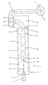
- the device for regulating the exhaust gas temperature is arranged in a drum device which is provided for the preparation of mixed material in asphalt production and which is designed as a drum 2 operating in countercurrent.
- the material required for asphalt production for example new material without Portions of bitumen etc. are introduced into the interior 4 of the drum 2 via the inlet openings 3 provided in the drum 2 and, as a result of the rotation of the drum 2, by means of blade-like internals 6 provided on the inner wall 5 of the drum 2 in the direction of the end of the drum in the vicinity of the burner 7 arranged there provided outlet openings 8, the scoop-shaped internals 6, depending on their design, distribute the material to be treated either over the entire cross section of the interior 4 of the drum 2 or over a portion thereof.
- an exhaust gas outlet 11 is provided, to which a first exhaust gas extraction line 12 is connected and which is connected via throttle valves 13 to an exhaust gas exhaust 14 which, for example, uses a suction fan 15 to filter systems (not shown) forwards.
- a second exhaust gas extraction line 16 is fixed concentrically in the interior 4 of the drum 2 by means of corresponding holding devices 17, the inlet opening 18 of which is arranged at a distance A from the outlet of the burner flame 19 from the burner 7.
- This second exhaust gas extraction line 16 is also guided concentrically through the exhaust gas outlet 11 arranged in the end wall 10 and ends in the vicinity of the throttle valves 13 of the first exhaust gas extraction line 12 via a further throttle valve 20 into the exhaust gas train 14.
- the throttle valves 13 and 20 can be adjustable depending on one another, furthermore it can be provided that the distance A between the burner flame 19 emerging from the burner 7 on the one hand and the inlet opening 18 of the second exhaust gas extraction line 16 is variable, with either the burner 7 in is designed to be displaceable in the axial longitudinal direction in the end wall 9 of the drum 2 or the length of the second exhaust gas extraction line 16 projecting into the interior 4 of the drum 2 can be varied, for example in the manner of a telescope.
- An advantageous positioning of the inlet opening 18 of the second exhaust gas extraction line 16 lies at the end of the burnout zone of the burner flame 19, starting from an advantageous setting of the burner 7 or the burner flame 19. At this point, the flame gases are still particularly hot, ie with a temperature of approx. 600 - 1,000 ° C.
- the extraction of these hot gases through the second exhaust gas extraction line 16 enables a temperature to be reached both in the area of the interior 4 of the drum 2, where the second exhaust gas extraction line 16 is arranged, and in the exhaust gas exhaust 14, which is referred to as the mixing temperature which can be regulated as required can be.
- the throttle valves 13 of the first exhaust gas suction line 12 remain fully open.
- the second (inner) exhaust gas extraction line 16 is connected via its Throttle valve 20 only partially open.
- the desired drum exhaust gas temperature can be set specifically for a specific operating situation by the blade-shaped internals 6. In the case of a material that is more fine-grained, the exhaust gas temperature would then be reduced, based on the same throughput rates. Since this would now disrupt the operating sequence, the suction power can be increased by the second exhaust gas suction line 16 for compensation. Alternatively, the temperature in the exhaust gas can rise if the rock is very coarse. At the same throughput, the amount of air drawn off through the second exhaust gas extraction line 16 would then be reduced to reduce the drum exhaust gas temperature. This would achieve the maximum possible heat exchange performance with the flap completely closed. This reserve in the heat exchange capacity of the device in connection with the controllable amount of air allows the exhaust gas temperature to be kept constant, which is particularly important for the downstream filters.
- the temperature of the material to be processed in a parallel drum e.g. B. asphalt granules are checked.
- a major advantage of the device described above is that no openings are to be arranged in the wall in the drum 2 in the central region. Such exhaust gas outlet openings influence the material flow of the material to be processed, at these points the material can accumulate, cake etc. These disadvantages are avoided by the above-described arrangement of a concentrically arranged second exhaust gas extraction line 16 in the interior 4 of the drum.
Landscapes
- Engineering & Computer Science (AREA)
- Architecture (AREA)
- Civil Engineering (AREA)
- Structural Engineering (AREA)
- Road Paving Machines (AREA)
Abstract
Description
- Die Erfindung betrifft eine Vorrichtung zur Regelung der Abgastemperatur in für die Aufbereitung von Mischgut bei der Asphaltherstellung vorgesehenen Trommelvorrichtungen, weiche in ihrem Innenraum an den Innenwänden angeordnete Einbauten aufweisen, von wel chen das aufzubereitende Mischgut erfaßt und entweder vollständig oder begrenzt über den freien Querschnitt des Innenraumes der Trommelvorrichtungen gefördert wird.
- Bei solchen bekannten Trommelvorrichtungen ist grundsätzlich zwischen zwei unterschiedlich arbeitenden Verfahren zu unterscheiden, nämlich einerseits zwischen einer im Gegenstrom und andererseits einer im Gleichstrom arbeitenden Trommelvorrichtung.
- Bei einer im Gegenstrom arbeitenden Trommelvorrichtung, im folgenden kurz Trommel genannt, wandert das zu erwärmende Material im Gegenstrom zu den Heizgasen durch die Trommel hindurch. Dabei wird zunächst das Material an dem dem Brenner der Trommel gegenüberliegenden Ende in den Innenraum eingebracht und durch auf der Innenwandung der Trommel angeordneten und als Rieselschaufeln ausgebildeten Einbauten zum Austausch der Wärme mit den Heizgasen fein verteilt in Richtung des Brenners gefördert. Im Bereich der stärksten Flammenstrahlung wird es von Einbauten gefördert, die einerseits den Ausbrand der Flamme möglichst wenig hindern und andererseits das Material aus dem unmittelbaren Ausbrandbereich der Flamme heraushalten und an den Trommelwandungen entlang fördern.
- Solche bisher bekannten Trommeln sind mit einem an dem dem Brenner gegenüberliegenden Ende vorgesehenen Absauggehäuse ausgerüstet. Die Abgastemperatur in diesem Absauggehäuse wird beeinflußt durch einerseits die Materialmenge in der Trommel und andererseits durch die Intensität des Materialschleiers, hervorgerufen durch die Einbauten. Je nach Durchsatzleistung und Materialqualität kann die Temperatur von 50°C bis weit über 400°C schwanken. Im Regelfall ist es durch Anpassung der Trommeleinbauten möglich, den Schwankungsbereich auf eine Abgastemperatur von ca. 90°C +/- 30°C einzustellen.
- Die Trommelabgase einer solchen Vorrichtung werden in nachgeschalteten Filterentstaubungen gereinigt, wobei regelmäßig zwischen der Trommel einerseits und dem nachgeschalteten Filter ein Vorabscheider zur Trennung der Sandanteile vom Fülleranteil vorgesehen ist, wobei die Trenngrenze im Idealfalle bei 0,09 mm Korngröße liegt.
- Die in den Filterentstaubungen vorgesehenen Filter sind äußerst empfindlich gegen Taupunktunterschreitungen und Übertemperaturen. Taupunktunterschreitungen können auch bei Temperaturen bis 100°C im Abgas eintreten. Die heutzutage eingesetzten Filtertücher sind kostengünstig, bis 140°C temperaturbeständig und handelsüblich. Gegen höhere Temperaturen beständige Filtertücher sind teurer, annähernd doppelt so teuer. Solche höher temperaturbeständigen Tücher sind allerdings sehr empfindlich gegen Taupunktunterschreitungen. Seit langem bemühen sich die Fachkreise,die Trommelabgastemperatur bei ca. 90°C konstant einzustellen. Wegen der vorerwähnten Schwankungen in der Durchsatzleistung und in der Materialqualität bzw. Beschaffenheit gelingt dies im Regelfall nicht. Zur Beeinflussung der Abgastemperatur wurden deshalb beispielsweise bereits in das Innere der Trommel einstehende Beschickungsbänder vorge schlagen, die das aufzubereitende Material unterschiedlich weit in die Trommel einwerfen. Durch die verminderte Länge der Wäremaustauschzone sollte dabei eine Regelung der Abgastemperatur erreicht werden. Die Erfolge durch eine Änderung im Materialstrom sind jedoch bisher unbefriedigend.
- Die eingangs beschriebene Trommel findet aber auch bei Asphaltaufbereitungsanlagen Verwendung, die mit zwei parallel arbeitenden Trommelvorrichtungen arbeiten, bei welchen die zweite Trommelvorrichtung eine im Gleichstrom arbeitende Trommel ist. In dieser Trommel wird entweder aufgebrochenes Altasphaltmaterial, auch Asphaltgranulat genannt, schonend aufbereitet und in einer nachgeschalteten dritten, beispielsweise als Zwangsmischer ausgebildeten Mischvorrichtung, mit dem in der ersten Trommelvorrichtung erwärmten Neu-Material vermischt und zu dem endgültigen Asphaltmischgut aufbereitet oder das aus der Trommel übergeleitete erwärmte Neu-Material mit Frischbitumen zum Asphaltmischgut aufbereitet.
- Eine solche Vorrichtung ist aus der US-PS 4,477,250 bekannt. Bei einer solchen Vorrichtung kann durch die Regelung der Abgastemperatur von der ersten Trommelvorrichtung die Wärmekapazität der zweiten Trommelvorrichtung erhöht und erniedrigt werden. Die Abgastemperaturregelung ist damit eine Regelung der Heizleistung für die nachgeschaltete zweite Trommel. Dies ist beispielsweise immer dann wichtig, wenn die zweite Trommel zur Erwärmung von beispielsweise temperaturempfindlichem Material wie eben Asphaltgranulat eingesetzt wird, wie dies beim Recycling von Asphaltgranulat erfolgt. Hierbei wird das Neumaterial in der ersten Trommel stark erhitzt. Die hierbei durch das Fehlen von Feinanteilen bereits stark erhöhten Abgastemperaturen werden zur Erwärmung von Granulat in der zweiten Trommel genutzt. Dieses Verfahren ist jedoch nach bisherigen Erkenntnissen wenig kontrollierbar, da keine Regeleinrichtung für die Abgastemperatur existiert.
- Aufgabe der vorliegenden Erfindung ist es deshalb, eine Vorrichtung zur Regelung der Abgastemperatur in einer im Gegenstrom arbeitenden Trommel zu schaffen, welche nicht den Materialdurchfluß, sondern die Abgasabsaugung beeinflußt und dadurch weiterhin gestattet, daß bei einer mit zwei parallel arbeitenden Trommeln ausgestatteten Aufbereitungsanlage die Temperatur des Asphaltgranulats in der nachgeschalteten Trommel gezielt kontrolliert bzw. gesteuert werden kann, wobei dann die Anordnung eines obenerwähnten Vorabscheiders zur Trennung der Sandanteile vom Fülleranteil entfallen kann.
- Die nachstehend beschriebene Lösung dieser Aufgabe geht dabei von dem aus der DE-PS 29 14 286 bekannten Verfahren zur Aufbereitung von bituminösem Mischgut in einer im Gleichstrom befeuerten Tommelvorrichtung aus, welche mit einer im Endbereich der Trommel angeschlossenen Absauganlage ausgerüstet ist und bei welcher die Heizgase auch im Bereich des Übergangs von der Trocknungszone in die Misch- und Umwälzzone teilweise aus der Trommel abgesaugt werden, wobei durch entsprechende Aufteilung der abzusaugenden Heizgas menge zwischen der Mittelabsaugung und dem Endabsaugekopf die Temperatur und der Feuchtigkeitsgehalt des Mischgutes in der Misch- und Umwälzzone regelbar sind.
Mit diesem bekannten Verfahren soll die Aufgabe gelöst werden, ein gutes Aufbereitungsergebnis, d. h. eine staubarme einwandfreie Umhüllung der Feststoffe mit bituminösem Bindemittel bei dessen minimaler thermischer Beanspruchung zu ermöglichen. D. h., innerhalb einer solchen für das bekannte Verfahren geeigneten Trommelvorrichtung wird bereits das fertige Asphaltmischgut durch Einbringung flüssigen (Neu-) Bitumens hergestellt. Dazu ist die Regelung der Abgasverhältnisse für die temperaturmäßige Bestimmung des aufbereiteten Materials notwendig, nicht etwa um, wie bei der dieser Anmeldung gestellten Aufgabe, die Einstellung der Abgastemperatur wegen der nachgeordneten Filtervorrichtung und/oder einer weiteren Trommelvorrichtung zu regulieren bzw. zu steuern. - Diese, der vorliegenden Anmeldung gestellte Aufgabe wird nun dadurch gelöst, daß bei einer Vorrichtung der eingangs genannten Art die Trommelvorrichtung eine im Gegenstrom arbeitende Trommel ist, welche an ihrem dem Brenner gegenüberliegenden Ende eine erste Abgasabsaugleitung sowie eine in ihrem Innenraum angeordnete rohrförmige zweite Abgasabsaugleitung aufweist, welche mit ihrer Einlaßöffnung in einem Abstand von dem Brenner angeordnet ist. Durch die Anordnung von zwei Absaugstellen in der Trommel können die Temperaturverhältnisse in dem der Einlaßöffnung der zweiten Abgasabsaugvorrichtung nachfolgenden Trommelbereich bis zur Einlaßöffnung der ersten Abgasabsaugleitung individuell geregelt werden, ohne daß der Materialfluß durch Öffnungen im Mittelbereich der Trommel beeinträchtigt wird.
- In vorteilhafter Weiterbildung der Erfindung ist die zweite Abgasabsaugleitung konzentrisch in der Trommel angeordnet und liegt deren Eintritt in den Innenraum der Trommel an der dem Brenner gegenüber angeordneten Stirnwand.
Durch diese Ausbildung der zweiten Abgasabsaugleitung bzw. deren Einbau in der Trommel ergibt sich eine einheitliche Innenraumgestaltung der Trommel, beginnend von der Einlaßöffnung der zweiten Abgasabsaugleitung bis hin zu dem dem Brenner gegenüberliegenden Stirnwand der Trommel. Entsprechend können in diesem Bereich auch die Einbauten zur Förderung des aufzubereitenden Gutes an den Trommelinnenwänden ausgebildet werden, so daß beispielsweise das zu fördernde und abzuwerfende Material nicht auf der Außenwandung der zweiten Abgasabsaugleitung liegen bleibt bzw. dort anbackt. - Erfindungsgemäß ist die zweite Abgasabsaugleitung in ihrer Länge bzw. mit ihrer Einlaßöffnung in ihrem Abstand von dem Brenner veränderbar. Durch diese Anordnung kann eine Abstimmung zwischen der Brennerflamme einerseits und der Aufnahmewirkung der Einlaßöffnung andererseits erfolgen.
- Vorteilhaft sind erste und zweite Abgasabsaugleitungen nach ihrem Austritt aus dem Brenner gegenüberliegenden Stirnwand der Trommel zusammengeführt und im Bereich ihrer Zusammenführung jeweils mit Drosselklappen ausgerüstet.
Durch diese Ausbildung wird erreicht, daß die Abgasanteile aus den jeweiligen Abgasabsaugleitungen gegeneinander geregelt und dosiert werden können. - Schließlich können erste und zweite Abgasabsaugleitung zusammen in eine zweite Trommelvorrichtung einmünden und wodurch eine Regelung der Filtereingangstemperatur ermöglicht wird. Diese Ausbildung gewährleistet weiterhin, daß zum einen die temperaturmäßig einstellbaren Abgase aus der ersten Trommelvorrichtung in einer nachgeschalteten weiteren Trommelvorrichtung energiesparend verwertet werden können und zum anderen, daß die weitere, vorteilhaft im Gleichstrom arbeitende Trommelvorrichtung gleichzeitig als Vorabscheider für den Sandanteil im Füllermaterial arbeitet und dieser Anteil am Ende dieser Trommel abgeschieden und separat dem Mischprozeß wieder zugeführt werden kann. Dadurch ersetzt diese Trommel den üblicherweise vor dem Filter eingebauten Vorabscheider.
- Ein die Erfindung nicht beschränkendes Ausführungsbeispiel wird nachfolgend anhand der einzigen Zeichnung beschrieben.
- Die Vorrichtung zur Regelung der Abgastemperatur ist in einer für die Aufbereitung von Mischgut bei der Asphaltherstellung vorgesehenen Trommelvorrichtung angeordnet, welche als im Gegenstrom arbeitende Trommel 2 ausgebildet ist. Das für die Asphaltherstellung benötigte Material, beispielsweise Neumaterial ohne Anteile von Bitumen etc., wird über in der Trommel 2 vorgesehene Einlaßöffnungen 3 in den Innenraum 4 der Trommel 2 eingebracht und in Folge der Drehung der Trommel 2 mittels an der Innenwandung 5 der Trommel 2 vorgesehene schaufelförmige Einbauten 6 in Richtung auf die am Trommel ende in Nähe des dort angeordneten Brenners 7 vorgesehenen Auslaßöffnungen 8 hingefördert, wobei die schaufelförmigen Einbauten 6, je nach ihrer Ausgestaltung, das aufzubereitende Material entweder über den gesamten Querschnitt des Innenraumes 4 der Trommel 2 oder über einen Teilbereich derselben verteilen.
- In der der den Brenner 7 enthaltenden Stirnwand 9 gegenüberliegenden Stirnwand 10 ist ein Abgasauslaß 11 vorgesehen, an welchen sich eine erste Abgasabsaugleitung 12 anschließt und welche über Drosselklappen 13 mit einem Abgasabzug 14 verbunden ist, welcher die Abgase beispielsweise über einen Absaugventilator 15 an nicht dargestellte Filteranlagen weiterleitet.
- Konzentrisch im Innenraum 4 der Trommel 2 ist eine zweite Abgasabsaugleitung 16 mittels entsprechender Haltevorrichtungen 17 befestigt, deren Einlaßöffnung 18 in einem Abstand A von dem Austritt der Brennerflamme 19 aus dem Brenner 7 angeordnet ist. Diese zweite Abgasabsaugleitung 16 ist ebenfalls konzentrisch durch den in der Stirnwand 10 angeordneten Abgasauslaß 11 hindurchgeführt und endet in der Nähe der Drosselklappen 13 der ersten Abgasabsaugleitung 12 über eine weitere Drosselklappe 20 in den Abgasab zug 14.
- Hierbei können die Drosselklappen 13 bzw. 20 in Abhängigkeit voneinander verstellbar sein, weiters kann vorgesehen werden, daß der Abstand A zwischen Austritt der Brennerflamme 19 aus dem Brenner 7 einerseits und der Einlaßöffnung 18 der zweiten Abgasabsaugleitung 16 variabel ist, wobei entweder der Brenner 7 in axialer Längsrichtung in der Stirnwand 9 der Trommel 2 verschieblich ausgebildet ist oder die zweite Abgasabsaugleitung 16 in ihrer in den Innenraum 4 der Trommel 2 hineinragenden Länge variierbar ist, beispielsweise nach Art eines Teleskopes.
- Eine vorteilhafte Positionierung der Einlaßöffnung 18 der zweiten Abgasabsaugleitung 16 liegt am Ende der Ausbrandzone der Brennerflamme 19, ausgehend von einer vorteilhaften Einstellung des Brenners 7 bzw. der Brennerflamme 19. An dieser Stelle sind die Flammengase noch besonders heiß, d. h. mit einer Temperatur vom ca. 600 - 1.000°C. Durch die Absaugung dieser heißen Gase durch die zweite Abgasabsaugleitung 16 wird ermöglicht, sowohl im Bereich des Innenraumes 4 der Trommel 2, wo die zweite Abgasabsaugleitung 16 angeordnet ist, als auch im Abgasabzug 14 eine Temperatur zu erreichen, welche jeweils als nach Bedarf regelbare Mischtemperatur bezeichnet werden kann. Bei Normalbetrieb bleiben die Drosselklappen 13 der ersten Abgasabsaugleitung 12 voll geöffnet. Die zweite (innere) Abgasabsaugleitung 16 wird über ihre Drosselklappe 20 nur teilweise geöffnet. Die gewünschte Trommelabgastemperatur kann durch die schaufelförmigen Einbauten 6 für eine bestimmte Betriebssituation gezielt eingestellt werden. Bei einem Material, welches feinkörniger ist, würde sich nun, ausgehend von gleichen Durchsatzleistungen, die Abgastemperatur reduzieren. Da dies nun den Betriebsablauf stören würde, kann zum Ausgleich die Absaugleistung durch die zweite Abgasabsaugleitung 16 erhöht werden. Alternativ dazu kann bei sehr grobem Gestein die Temperatur im Abgas ansteigen. Bei gleicher Durchsatzleistung würde dann zur Reduzierung der Trommelabgastemperatur die durch die zweite Abgasabsaugleitung 16 abgesaugte Luftmenge reduziert. Hierdurch würde die maximal mögliche Wärmeaustauschleistung bei vollständig geschlossener Klappe erreicht werden. Durch diese Reserve in der Wärmeaustauschkapazität der Vorrichtung kann in Verbindung mit der regelbaren Luftmenge die Abgastemperatur konstant gehalten werden, was insbesondere für die nachgeschalteten Filter von Bedeutung ist.
- Nach der eingangs geschilderten zweiten Aufgabenstellung kann durch diese Vorrichtung auch die Temperatur des in einer parallel arbeitenden Trommel aufzubereitenden Materials, z. B. Asphaltgranulat, kontrolliert werden.
- Ein wesentlicher Vorteil der vorbeschriebenen Vorrichtung liegt darin, daß keine Öffnungen in der Wandung in der Trommel 2 im Mittelbereich anzuordnen sind. Solche Abgas-Austrittsöffnungen beeinflussen den Materialfluß des aufzubereitenden Materials, an diesen Stellen kann sich das Material stauen, anbacken etc. Diese Nachteile werden durch die vorbeschriebene Anordnung einer konzentrisch angeordneten zweiten Abgasabsaugleitung 16 im Innenraum 4 der Trommel vermieden.
Claims (8)
Priority Applications (1)
| Application Number | Priority Date | Filing Date | Title |
|---|---|---|---|
| AT89115123T ATE86323T1 (de) | 1988-08-22 | 1989-08-16 | Vorrichtung zur regelung der abgastemperatur in fuer die aufbereitung von mischgut bei der asphaltherstellung vorgesehenen trommelvorrichtungen. |
Applications Claiming Priority (3)
| Application Number | Priority Date | Filing Date | Title |
|---|---|---|---|
| DE8810609U DE8810609U1 (de) | 1988-08-22 | 1988-08-22 | Vorrichtung zur Regelung der Abgastemperatur in für die Aufbereitung von Mischgut bei der Asphaltherstellung vorgesehenen Trommelvorrichtungen |
| DE3828425 | 1988-08-22 | ||
| DE3828425A DE3828425A1 (de) | 1988-08-22 | 1988-08-22 | Vorrichtung zur regelung der abgastemperatur in fuer die aufbereitung von mischgut bei der asphaltherstellung vorgesehenen trommelvorrichtung |
Publications (3)
| Publication Number | Publication Date |
|---|---|
| EP0355701A2 true EP0355701A2 (de) | 1990-02-28 |
| EP0355701A3 EP0355701A3 (en) | 1990-10-10 |
| EP0355701B1 EP0355701B1 (de) | 1993-03-03 |
Family
ID=39357659
Family Applications (1)
| Application Number | Title | Priority Date | Filing Date |
|---|---|---|---|
| EP89115123A Expired - Lifetime EP0355701B1 (de) | 1988-08-22 | 1989-08-16 | Vorrichtung zur Regelung der Abgastemperatur in für die Aufbereitung von Mischgut bei der Asphaltherstellung vorgesehenen Trommelvorrichtungen |
Country Status (2)
| Country | Link |
|---|---|
| EP (1) | EP0355701B1 (de) |
| DE (2) | DE8810609U1 (de) |
Cited By (2)
| Publication number | Priority date | Publication date | Assignee | Title |
|---|---|---|---|---|
| FR2956125A1 (fr) * | 2010-02-11 | 2011-08-12 | Famaro | Installation de production de produits enrobes bitumineux. |
| US9611578B2 (en) | 2004-10-22 | 2017-04-04 | Whirlpool Corporation | Modular laundry system |
Families Citing this family (4)
| Publication number | Priority date | Publication date | Assignee | Title |
|---|---|---|---|---|
| US7628043B2 (en) | 2000-07-25 | 2009-12-08 | Whirlpool Corporation | Modular laundry system with horizontal modules |
| US7617702B2 (en) | 2000-07-25 | 2009-11-17 | Whirlpool Corporation | Modular laundry system with cabinet module |
| US7624600B2 (en) | 2000-07-25 | 2009-12-01 | Whirlpool Corporation | Modular laundry system with horizontally arranged cabinet module |
| US11851221B2 (en) | 2022-04-21 | 2023-12-26 | Curium Us Llc | Systems and methods for producing a radioactive drug product using a dispensing unit |
Family Cites Families (6)
| Publication number | Priority date | Publication date | Assignee | Title |
|---|---|---|---|---|
| DE528655C (de) * | 1931-07-02 | Albrecht Reiser Fa | Trockentrommel fuer Strassenbaustoffe | |
| GB1443424A (en) * | 1972-10-13 | 1976-07-21 | Redland Roadstone Ltd | Method and apparatus for production of coated roadstone |
| DE2914286C2 (de) * | 1979-04-09 | 1982-03-25 | Wibau Industrie und Verwaltung GmbH, 6466 Gründau | Verfahren zur Aufbereitung von bituminösem Mischgut in einem im Gleichstrom befeuerten Trommelmischer mit einer im Endbereich des Trommelmischers angeschlossenen Ansaugeanlage |
| US4477250A (en) * | 1983-03-07 | 1984-10-16 | Mechtron International Corporation | Asphalt recycle plant and method |
| DE3414365A1 (de) * | 1984-04-16 | 1985-10-24 | Erich Dipl.-Ing. 8000 München Schambeck | Einrichtung zur aufbereitung von bituminoesem mischgut, insbesondere strassenbauasphalt |
| DE3441382A1 (de) * | 1984-11-13 | 1986-05-22 | Deutsche Asphalt Gmbh, 6000 Frankfurt | Verfahren und vorrichtung zum aufbereiten von asphalt |
-
1988
- 1988-08-22 DE DE8810609U patent/DE8810609U1/de not_active Expired
- 1988-08-22 DE DE3828425A patent/DE3828425A1/de not_active Withdrawn
-
1989
- 1989-08-16 EP EP89115123A patent/EP0355701B1/de not_active Expired - Lifetime
Cited By (5)
| Publication number | Priority date | Publication date | Assignee | Title |
|---|---|---|---|---|
| US9611578B2 (en) | 2004-10-22 | 2017-04-04 | Whirlpool Corporation | Modular laundry system |
| US10041201B2 (en) | 2004-10-22 | 2018-08-07 | Whirlpool Corporation | Modular laundry system |
| US10443176B2 (en) | 2004-10-22 | 2019-10-15 | Whirlpool Corporation | Laundry system |
| FR2956125A1 (fr) * | 2010-02-11 | 2011-08-12 | Famaro | Installation de production de produits enrobes bitumineux. |
| WO2011098692A1 (fr) * | 2010-02-11 | 2011-08-18 | Famaro | Installation de production de produits enrobes bitumineux |
Also Published As
| Publication number | Publication date |
|---|---|
| EP0355701B1 (de) | 1993-03-03 |
| EP0355701A3 (en) | 1990-10-10 |
| DE8810609U1 (de) | 1988-10-27 |
| DE3828425A1 (de) | 1990-03-01 |
Similar Documents
| Publication | Publication Date | Title |
|---|---|---|
| EP0183079B1 (de) | Verfahren und Vorrichtung zur Aufbereitung von Asphaltmischgut unter Wiederverwendung aufgebrochenen Alt-Asphalts | |
| EP0204912A2 (de) | Verfahren und Vorrichtung zum Verbrennen flüssiger und/oder fester Brennstoffe in pulverisierter Form | |
| DE69004594T2 (de) | Verfahren zur Verbrennung von Kohlenstaub. | |
| DE2716216A1 (de) | Brenner fuer pulverfoermigen brennstoff | |
| DE2736607C2 (de) | Verfahren und Vorrichtung zur thermischen Behandlung von feinkörnigem Gut mit heißen Gasen | |
| DE3541116A1 (de) | Verteiler zur verwendung bei einem kohlebeheizten ofen | |
| DE3013900C2 (de) | Einrichtung zum Trocknen von feuchtem Material | |
| EP0131162B1 (de) | Vorrichtung zum Aufbereiten von Strassendeckenbelägen | |
| EP0355701A2 (de) | Vorrichtung zur Regelung der Abgastemperatur in für die Aufbereitung von Mischgut bei der Asphaltherstellung vorgesehenen Trommelvorrichtungen | |
| DE2440053C3 (de) | Vorrichtung zur thermischen Behandlung von feuchtem Rohmaterial, zum Beispiel zum Trocknen von Schlämmen | |
| DE3346536C2 (de) | Vorbrenner für Zementrohmehl | |
| DE2617839C3 (de) | Einrichtung zum Aufbereiten von bituminösem Mischgut mit einer im Gleichstrom befeuerten Drehtrommel | |
| DE3628106C2 (de) | ||
| DE3616995C2 (de) | ||
| EP0025186A1 (de) | Verfahren und Vorrichtung zum Aufbereiten von bituminösem Mischgut in einer befeuerten Drehtrommel | |
| EP0078250A1 (de) | Verfahren und Vorrichtung zum Herstellen von Zement | |
| EP0013946B1 (de) | Einrichtung zum Aufbereiten von bituminösem Mischgut | |
| DE2914286C2 (de) | Verfahren zur Aufbereitung von bituminösem Mischgut in einem im Gleichstrom befeuerten Trommelmischer mit einer im Endbereich des Trommelmischers angeschlossenen Ansaugeanlage | |
| DE2908003C2 (de) | Vorrichtung zur trockenen absorptiven Bindung luftfremder Stoffe an Additive | |
| DE2656616A1 (de) | Vorrichtung zum erhitzen von zur glasschmelze bestimmten rohmaterialien | |
| DE2008646B2 (de) | Vorrichtung zum Erzeugen von Agglomeraten aus einer Suspension | |
| DE2834784C2 (de) | Verfahren und Vorrichtung zum Umhüllen von vorzugsweise kornabgestuftem mineralischem Schüttgut | |
| DE911320C (de) | Kohlenstaubfeuerung mit mehreren von einem Verteiler mit Kohlenstaub unterschiedlichen Feinheitsgrades gespeisten Brennern, insbesondere fuer Drehoefen | |
| DE3538325A1 (de) | Vorrichtung zum erwaermen und durchmischen von zur herstellung von strassenbelag verwendeten materialien | |
| DE3010918C2 (de) | Drehtrommel, insbesondere zur Aufbereitung bituminösen Mischgutes |
Legal Events
| Date | Code | Title | Description |
|---|---|---|---|
| PUAI | Public reference made under article 153(3) epc to a published international application that has entered the european phase |
Free format text: ORIGINAL CODE: 0009012 |
|
| AK | Designated contracting states |
Kind code of ref document: A2 Designated state(s): AT CH DE FR GB IT LI NL |
|
| PUAL | Search report despatched |
Free format text: ORIGINAL CODE: 0009013 |
|
| AK | Designated contracting states |
Kind code of ref document: A3 Designated state(s): AT CH DE FR GB IT LI NL |
|
| 17P | Request for examination filed |
Effective date: 19901213 |
|
| 17Q | First examination report despatched |
Effective date: 19911015 |
|
| GRAA | (expected) grant |
Free format text: ORIGINAL CODE: 0009210 |
|
| AK | Designated contracting states |
Kind code of ref document: B1 Designated state(s): AT CH DE FR GB IT LI NL |
|
| REF | Corresponds to: |
Ref document number: 86323 Country of ref document: AT Date of ref document: 19930315 Kind code of ref document: T |
|
| ITF | It: translation for a ep patent filed | ||
| GBT | Gb: translation of ep patent filed (gb section 77(6)(a)/1977) |
Effective date: 19930304 |
|
| REF | Corresponds to: |
Ref document number: 58903645 Country of ref document: DE Date of ref document: 19930408 |
|
| ET | Fr: translation filed | ||
| PLBE | No opposition filed within time limit |
Free format text: ORIGINAL CODE: 0009261 |
|
| STAA | Information on the status of an ep patent application or granted ep patent |
Free format text: STATUS: NO OPPOSITION FILED WITHIN TIME LIMIT |
|
| 26N | No opposition filed | ||
| PGFP | Annual fee paid to national office [announced via postgrant information from national office to epo] |
Ref country code: CH Payment date: 19950620 Year of fee payment: 7 |
|
| PGFP | Annual fee paid to national office [announced via postgrant information from national office to epo] |
Ref country code: FR Payment date: 19950623 Year of fee payment: 7 |
|
| PGFP | Annual fee paid to national office [announced via postgrant information from national office to epo] |
Ref country code: GB Payment date: 19950810 Year of fee payment: 7 |
|
| PGFP | Annual fee paid to national office [announced via postgrant information from national office to epo] |
Ref country code: NL Payment date: 19950830 Year of fee payment: 7 Ref country code: AT Payment date: 19950830 Year of fee payment: 7 |
|
| PG25 | Lapsed in a contracting state [announced via postgrant information from national office to epo] |
Ref country code: GB Effective date: 19960816 Ref country code: AT Effective date: 19960816 |
|
| PG25 | Lapsed in a contracting state [announced via postgrant information from national office to epo] |
Ref country code: LI Effective date: 19960831 Ref country code: CH Effective date: 19960831 |
|
| PG25 | Lapsed in a contracting state [announced via postgrant information from national office to epo] |
Ref country code: NL Effective date: 19970301 |
|
| GBPC | Gb: european patent ceased through non-payment of renewal fee |
Effective date: 19960816 |
|
| REG | Reference to a national code |
Ref country code: CH Ref legal event code: PL |
|
| PG25 | Lapsed in a contracting state [announced via postgrant information from national office to epo] |
Ref country code: FR Effective date: 19970430 |
|
| NLV4 | Nl: lapsed or anulled due to non-payment of the annual fee |
Effective date: 19970301 |
|
| REG | Reference to a national code |
Ref country code: FR Ref legal event code: ST |
|
| PGFP | Annual fee paid to national office [announced via postgrant information from national office to epo] |
Ref country code: DE Payment date: 20050812 Year of fee payment: 17 |
|
| PG25 | Lapsed in a contracting state [announced via postgrant information from national office to epo] |
Ref country code: IT Free format text: LAPSE BECAUSE OF NON-PAYMENT OF DUE FEES;WARNING: LAPSES OF ITALIAN PATENTS WITH EFFECTIVE DATE BEFORE 2007 MAY HAVE OCCURRED AT ANY TIME BEFORE 2007. THE CORRECT EFFECTIVE DATE MAY BE DIFFERENT FROM THE ONE RECORDED. Effective date: 20050816 |
|
| PG25 | Lapsed in a contracting state [announced via postgrant information from national office to epo] |
Ref country code: DE Free format text: LAPSE BECAUSE OF NON-PAYMENT OF DUE FEES Effective date: 20070301 |