EP0355404B1 - Vorrichtung zur Sicherung von Gegenständen - Google Patents
Vorrichtung zur Sicherung von Gegenständen Download PDFInfo
- Publication number
- EP0355404B1 EP0355404B1 EP89113316A EP89113316A EP0355404B1 EP 0355404 B1 EP0355404 B1 EP 0355404B1 EP 89113316 A EP89113316 A EP 89113316A EP 89113316 A EP89113316 A EP 89113316A EP 0355404 B1 EP0355404 B1 EP 0355404B1
- Authority
- EP
- European Patent Office
- Prior art keywords
- trigger circuit
- receiver
- switch
- banknotes
- radio signals
- Prior art date
- Legal status (The legal status is an assumption and is not a legal conclusion. Google has not performed a legal analysis and makes no representation as to the accuracy of the status listed.)
- Expired - Lifetime
Links
Images


Classifications
-
- G—PHYSICS
- G08—SIGNALLING
- G08B—SIGNALLING OR CALLING SYSTEMS; ORDER TELEGRAPHS; ALARM SYSTEMS
- G08B15/00—Identifying, scaring or incapacitating burglars, thieves or intruders, e.g. by explosives
- G08B15/02—Identifying, scaring or incapacitating burglars, thieves or intruders, e.g. by explosives with smoke, gas, or coloured or odorous powder or liquid
Definitions
- the invention relates to a device for securing objects according to the preamble of patent claim 1.
- the preamble of the main claim is based on a device for securing objects according to GB-PS 1299303.
- the known theft protection system is located in a prepared bundle of banknotes and has a trigger circuit for igniting an emission body, which is activated by a receiver when the receiver receives the radio signals from a transmitter located in the escape area of the perpetrator.
- the emission body is ignited after a timer provided in the trigger circuit has expired.
- the power supply to the receiver is interrupted with a microswitch until how the prepared bundle of bills is in a security cassette. As soon as the bundle of notes is removed from the cassette, the trigger circuit can be activated. It is disadvantageous that the bundle of banknotes cannot be removed from the security cassette and placed in another location without the risk of false triggering.
- the device for securing banknotes is used in financial institutions, people who are present in the financial institution if the emission body is ignited in an uncontrolled manner can be endangered by the surprised and irritated perpetrator. This risk is particularly great in the event of a bank robbery, since the handing over of the money packages is generally forced by taking hostages. The emission body could be ignited at a time when the hostages are still under the control of the perpetrator.
- the invention has for its object to provide a device for securing objects according to the preamble of claim 1, in which the risk of untimely ignition of the emission body is reduced, so that a risk to uninvolved people is avoided.
- a switching device which blocks the trigger circuit for igniting the emission body in the idle state of the device, so that false triggering by radio signals or other trigger criteria is forcibly prevented. If the object is handed over to the perpetrator, the perpetrator with the object to be secured, as far as the device for securing banknotes is used, will still be in the financial institution.
- the switching device has the task of preventing ignition immediately after the handover of the money packets to which the device is coupled and only releasing the release when the perpetrator has left the financial institution and is on the run.
- the switching device starts a timer which blocks the operation of the trigger circuit during its running time.
- the switching device contains a second switch which responds to movements of the object and which then prepares the trigger circuit for igniting the emission body when the object moves after the first timer has expired.
- the switch which responds to movements of the object, can react to an acceleration or an inclination of the object from the normal position. A triggering with radio signals is only possible under the conditions that the object is handed over to the perpetrator with the device and the perpetrator moves the object after the first delay time.
- the trigger circuit causes the emission body to ignite when the receiver receives the radio signals after a second timer has expired or when the radio signals from a transmitter of short range no longer are received.
- the second delay time is longer than the first delay time and is such that the perpetrator is already on the run and may have left the financial institution. Only now, according to the first variant, can the receiver receive the radio signals and activate the trigger circuit.
- the trigger circuit can then be caused to ignite the emission body according to another embodiment of the invention if a movement of the Subject occurs and after the first timer the receiver no longer receives the radio signals of a transmitter of short range.
- the range of the transmitter can be dimensioned such that an ignition takes place automatically after the first timer has expired, after the perpetrator has left the bank and is therefore outside the range of the transmitter. In addition, the perpetrator cannot prevent the triggering by electrically shielding the receiver. Electrical shielding leads to the ignition of the emission body.
- the emission body, the switching device, the trigger circuit and the receiver are expediently located in a cavity of a prepared bundle of bills.
- the device is therefore indistinguishable from a real bundle of banknotes and can be handed over to the perpetrator with other bundles of banknotes unnoticed and safely.
- the device can also be used to secure other movable valuables, such as jewelry or secret documents.
- FIG. 1 shows a device for securing banknotes in perspective view and an associated transport cassette 21.
- the part of the device which is handed over to the perpetrator in the event of a robbery has the outer shape of a bundle of banknotes 20 which cannot be distinguished from a real bundle of banknotes.
- the prepared bundle of banknotes 20 is stored in a lockable transport cassette 21 during transport and for storage outside the operating hours.
- the dimensions of the interior of the transport cassette 21 correspond approximately to the size of the bundle of banknotes.
- the transport cassette has the task to rule out an unintended ignition of the emission body 10.
- a permanent magnet 14 is provided on the bottom of the transport cassette, which interacts with a reed contact 2 indicated by dashed lines and located in the bundle of banknotes and inactivates the device as long as it is in the transport cassette.
- the permanent magnet 14 is arranged on the bottom of the cassette directly below the reed contact of a bundle of banknotes inserted into the transport cassette, so that the reed contact 2 is actuated by the magnetic field of the permanent magnet and the power supply to the device is switched off.
- the prepared bundle of banknotes 20 shown schematically in FIG. 2 consists of sheets of paper stuck one above the other the size of a common banknote, the thickness of the resulting bundle of paper corresponding to the thickness of the commonly used bundles of money.
- the paper sheets glued together are punched out in a rectangular shape in the central region, so that a cavity 24 results.
- the control electronics 19 as well as the electric igniter 9 and the emission body 10 are located in this cavity 24.
- the emission body 10 is ignited by the electric igniter 9 with the detonating cords 22 and leads to intensive smoke development lasting about 20 seconds.
- the already mentioned reed contact 2, a tilt switch 4, a battery 1 necessary for the power supply and a receiving coil 13a are accommodated in the bundle of banknotes 20 as further components.
- the function of the individual components will be explained in the following in FIG. 3.
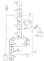
- Fig. 3 shows a block diagram of the device with an active radio trigger.
- the blocks belonging to the control electronics 19, which consist of a switching device 17 and a trigger circuit 18, are framed by dashed lines.
- the power supply to the control electronics 19 and the electric igniter 9 for the emission body 10 takes place via the dry battery 1.
- the dry battery has small dimensions, so that it can be accommodated in the space of the bundle of banknotes 20 to save space.
- the dry cell is able to deliver a high short-circuit current, which is necessary for the ignition of the emission body.
- the battery voltage is controlled by a voltage monitor 15, which is designed so that an acoustic signal is given in standby mode if the correct operation of the control electronics is guaranteed for at least ten days and the electric igniter can be safely ignited.
- the battery voltage is indicated acoustically by a low, short buzzer sound, which occurs in an interval of approx. 30 seconds repeated.
- the battery voltage is applied to the control electronics 19 so that it is ready for operation.
- a first timer 3 is started, the output voltage of which becomes positive within a first delay time of approximately 60 zec.
- a tilt switch 4 is provided, which delivers positive output pulses when the prepared bundle of banknotes is rotated by more than 45 ° from a horizontal position.
- the negated output signal of the first timing element 3 and the output signal of the tilt switch 4 are combined in an AND gate 5.
- the output signal of the AND gate 5 is positive if, after the first timer 3 has expired, the bundle of banknotes is brought out of its horizontal normal position by more than 45 °.
- the bundle of banknotes 20 can therefore be removed from the transport cassette 21 in the financial institution and placed within the first delay time as often as desired in different locations and rotated in the process without the emission body 10 being able to be ignited.
- the positive output signal of the AND gate 5 starts a second timer 6 when the prepared bundle of banknotes is possibly handed over to the bank robber together with other real banknotes bundles and the bank robber escapes the banknotes bundle from the normal position after the first timer 3 has expired.
- the output of the second timer 6 is connected to the negated input of a second AND gate 7.
- the output signal is at the other, non-negated input of the AND gate 7 of a receiver 8.
- the receiver receives, via a receiving coil 13a, the radio pulses emitted by an antenna 13b of a transmitter 12, with which the emission body 10 can be ignited actively, ie at any time, after the second timer has expired. After the second timer has expired, the perpetrator will already have left the financial institution and will be on the run. Only now can the emission body be made to explode by sending the radio signals. If after the second delay time of approx. 300 seconds has elapsed, the output voltage of the timing element 6 drops back to 0 V and the receiver delivers a positive output pulse, the output signal of the AND gate 7 also becomes positive and the electric igniter 9 is connected directly to the battery voltage 1 . The emission body explodes and intensive smoke development begins.
- the pulse diagrams ag for the control electronics in which the voltage profiles at points ag of the block diagram of FIG. 3 can be seen.
- the battery voltage a is monitored by the voltage monitor 15.
- the battery voltage of the control electronics b is switched on with the reed contact 2 and the first timer c is started for the delay time T 1.
- the pulses d of the tilt switch 4 activate after the expiry of the first timer at time t3, the second timer e for the delay time T2.
- the emission body is ignited with the ignition pulse g.
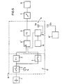
- FIG. 5 shows an exemplary embodiment of a device with passive radio triggering. This exemplary embodiment differs from the device with active radio triggering from FIG. 2 in that the emission body 10 cannot be ignited by radio signals at any time after the second timer 6 has expired.
- a transmitter 12 'with low power and therefore short range This sends a coded signal at intervals of 5 seconds.
- This signal is evaluated by a tuned to the frequency and the coded identifier of the installed transmitter receiver 8 'of the device.
- the output signal of the receiver 8 ' is connected to an inverted input of an AND gate 5' with three inputs, the other two inputs being connected to the output signal of the first timer 3 and the tilt switch 4.
- the second AND gate 7 of the exemplary embodiment described in FIG. 3 is omitted.
- the second timer 6 is started under the condition that the tilt switch 4 is actuated after the first timer 3 and the receiver 8 'no longer receives a coded radio signal.
- the ignition is therefore blocked as long as the bank robber with the prepared bundle of banknotes is within range of the transmitter.
- the range of the transmitter 12 ' is such that the emission body can only be ignited outside the financial institution. The people present in the financial institution can therefore no longer be endangered. With such an automatic triggering, the bank robber cannot ignite the emission body prevent by electrically shielding the bundle of banknotes. Electrical shielding, in which the receiver no longer receives radio signals, leads to ignition.
- An additional reception monitoring circuit 16 indicates the operational readiness of the device by signaling a reception failure with the same acoustic buzzing sound as the voltage monitor 15 if the receiver has not received the coded signal of the transmitter during the first delay time at least five times.
Landscapes
- Physics & Mathematics (AREA)
- General Physics & Mathematics (AREA)
- Burglar Alarm Systems (AREA)
- Purses, Travelling Bags, Baskets, Or Suitcases (AREA)
- Transition And Organic Metals Composition Catalysts For Addition Polymerization (AREA)
- Pile Receivers (AREA)
Priority Applications (1)
| Application Number | Priority Date | Filing Date | Title |
|---|---|---|---|
| AT89113316T ATE67877T1 (de) | 1988-07-23 | 1989-07-20 | Vorrichtung zur sicherung von gegenstaenden. |
Applications Claiming Priority (2)
| Application Number | Priority Date | Filing Date | Title |
|---|---|---|---|
| DE3825051A DE3825051C1 (sv) | 1988-07-23 | 1988-07-23 | |
| DE3825051 | 1988-07-23 |
Publications (3)
| Publication Number | Publication Date |
|---|---|
| EP0355404A2 EP0355404A2 (de) | 1990-02-28 |
| EP0355404A3 EP0355404A3 (en) | 1990-03-07 |
| EP0355404B1 true EP0355404B1 (de) | 1991-09-25 |
Family
ID=6359376
Family Applications (1)
| Application Number | Title | Priority Date | Filing Date |
|---|---|---|---|
| EP89113316A Expired - Lifetime EP0355404B1 (de) | 1988-07-23 | 1989-07-20 | Vorrichtung zur Sicherung von Gegenständen |
Country Status (5)
| Country | Link |
|---|---|
| EP (1) | EP0355404B1 (sv) |
| AT (1) | ATE67877T1 (sv) |
| DE (2) | DE3825051C1 (sv) |
| ES (1) | ES2026292T3 (sv) |
| GR (1) | GR3002796T3 (sv) |
Families Citing this family (4)
| Publication number | Priority date | Publication date | Assignee | Title |
|---|---|---|---|---|
| US5196828A (en) * | 1992-01-14 | 1993-03-23 | U.S. Currency Protection Corp. | Bendable currency security dye pack |
| EP0629984A1 (en) * | 1993-06-01 | 1994-12-21 | Ici Americas Inc. | Anti-theft system for jewellery |
| DE69413607T2 (de) * | 1993-07-02 | 1999-09-02 | Us Currency Protection | Sicherheitspäckchen mit Farbsprüheinrichtung und flexiblem flammwidrigen chemischen Beutel |
| GB2372799B (en) * | 2000-12-01 | 2005-03-23 | Ibp Internat Ltd | Security system including a smoke composition |
Family Cites Families (7)
| Publication number | Priority date | Publication date | Assignee | Title |
|---|---|---|---|---|
| DE1566715A1 (de) * | 1967-03-01 | 1970-01-22 | Merk Gmbh Telefonbau Fried | Schaltungsanordnung zur UEberwachung der Lageaenderung von Gegenstaenden |
| US3618059A (en) * | 1968-06-19 | 1971-11-02 | Milton F Allen | Electronic detection and tracing means |
| DE2043949A1 (de) * | 1970-09-04 | 1972-06-15 | King G | Explosivkörper und Vorrichtung zu seiner Handhabung |
| GB1299303A (en) * | 1971-02-15 | 1972-12-13 | Harold Jennings Robeson | A robbery protection system and device for temporarily disabling a robber or visibly marking his location |
| US3828341A (en) * | 1972-01-20 | 1974-08-06 | Ici America Inc | Alarm apparatus for facilitating the detection of an unauthorized removal of property |
| DE2933893C2 (de) * | 1979-08-22 | 1983-03-17 | Walter 8000 München Hamann | Transportsicherung |
| AU527839B2 (en) * | 1980-02-04 | 1983-03-24 | Protector Patent Development and Marketing Pty Ltd | Theft detection and identification |
-
1988
- 1988-07-23 DE DE3825051A patent/DE3825051C1/de not_active Expired - Lifetime
-
1989
- 1989-07-20 DE DE8989113316T patent/DE58900322D1/de not_active Expired - Fee Related
- 1989-07-20 EP EP89113316A patent/EP0355404B1/de not_active Expired - Lifetime
- 1989-07-20 AT AT89113316T patent/ATE67877T1/de active
- 1989-07-20 ES ES198989113316T patent/ES2026292T3/es not_active Expired - Lifetime
-
1991
- 1991-09-26 GR GR91401276T patent/GR3002796T3/el unknown
Also Published As
| Publication number | Publication date |
|---|---|
| DE58900322D1 (de) | 1991-10-31 |
| ATE67877T1 (de) | 1991-10-15 |
| ES2026292T3 (es) | 1992-04-16 |
| EP0355404A3 (en) | 1990-03-07 |
| GR3002796T3 (en) | 1993-01-25 |
| DE3825051C1 (sv) | 1990-01-18 |
| EP0355404A2 (de) | 1990-02-28 |
Similar Documents
| Publication | Publication Date | Title |
|---|---|---|
| DE2302701C2 (de) | Alarmvorrichtung | |
| EP0047486A1 (de) | Schaltungsanordnung zur elektronisch codierten Verriegelung von Schlössern | |
| DE2827193B2 (de) | Sicherheitstransportbehälter | |
| DE19512266A1 (de) | Vorrichtung zum Schutz einer elektronischen Schaltung vor Manipulation | |
| EP0355404B1 (de) | Vorrichtung zur Sicherung von Gegenständen | |
| DE3404507A1 (de) | Fernmeldevorrichtung | |
| DE3100638A1 (de) | Einbruchs- und diebstahlsicherung bei fahrzeugen | |
| DE3234859A1 (de) | Schluesseldepot | |
| WO1989000520A1 (en) | Car radio with theft protection | |
| CH624284A5 (en) | Portable container which is protected against theft and/or break-in | |
| DE3538786C2 (sv) | ||
| WO1994026565A1 (de) | Sicherungssystem | |
| DE2805759C3 (de) | Wert-Transportbehälter mit einer in einem Gehäuse angeordneten Vorrichtung zum Schütze des Transportgutes gegen Diebstahl | |
| EP0682610B1 (de) | Diebstahl-sicherungsvorrichtung | |
| AT389732B (de) | Schloss mit elektronischer codierung | |
| DE102014114859A1 (de) | Elektromechanisches Schließsystem für Brandschutztüren | |
| DE3639277C2 (de) | Fernwirkeinrichtung | |
| DE3119112A1 (de) | Einrichtung zur sicherung von gegenstaenden gegen unbefugtes mitnehmen | |
| DE3503933C2 (sv) | ||
| DE3220108A1 (de) | Verfahren zum zuenden einer explosiven vorrichtung und auf diese weise erhaltene explosive vorrichtung | |
| DE3400526A1 (de) | Einrichtung zum ueberwachen von geldscheinbuendeln | |
| WO1987001844A1 (en) | Burglary or anti-theft protection system | |
| DE3706870B3 (de) | Seemine mit akustischer Zündeinrichtung und Fernwirkeinrichtung zum Schärfen und/oder Entschärfen | |
| DE4416118C1 (de) | Verfahren zum Entriegeln einer aktivierten Wegfahrsicherung eines Fahrzeuges | |
| DE2918766C2 (de) | Vorrichtung zum Sichern größerer Bargeldbestände gegen Banküberfälle |
Legal Events
| Date | Code | Title | Description |
|---|---|---|---|
| PUAI | Public reference made under article 153(3) epc to a published international application that has entered the european phase |
Free format text: ORIGINAL CODE: 0009012 |
|
| PUAL | Search report despatched |
Free format text: ORIGINAL CODE: 0009013 |
|
| AK | Designated contracting states |
Kind code of ref document: A2 Designated state(s): AT BE CH DE ES FR GB GR IT LI LU NL SE |
|
| AK | Designated contracting states |
Kind code of ref document: A3 Designated state(s): AT BE CH DE ES FR GB GR IT LI LU NL SE |
|
| 17P | Request for examination filed |
Effective date: 19900321 |
|
| 17Q | First examination report despatched |
Effective date: 19900727 |
|
| GRAA | (expected) grant |
Free format text: ORIGINAL CODE: 0009210 |
|
| AK | Designated contracting states |
Kind code of ref document: B1 Designated state(s): AT BE CH DE ES FR GB GR IT LI LU NL SE |
|
| REF | Corresponds to: |
Ref document number: 67877 Country of ref document: AT Date of ref document: 19911015 Kind code of ref document: T |
|
| ITF | It: translation for a ep patent filed |
Owner name: ING. A. GIAMBROCONO & C. S.R.L. |
|
| ET | Fr: translation filed | ||
| REF | Corresponds to: |
Ref document number: 58900322 Country of ref document: DE Date of ref document: 19911031 |
|
| GBT | Gb: translation of ep patent filed (gb section 77(6)(a)/1977) | ||
| REG | Reference to a national code |
Ref country code: ES Ref legal event code: FG2A Ref document number: 2026292 Country of ref document: ES Kind code of ref document: T3 |
|
| PLBE | No opposition filed within time limit |
Free format text: ORIGINAL CODE: 0009261 |
|
| STAA | Information on the status of an ep patent application or granted ep patent |
Free format text: STATUS: NO OPPOSITION FILED WITHIN TIME LIMIT |
|
| 26N | No opposition filed | ||
| REG | Reference to a national code |
Ref country code: GR Ref legal event code: FG4A Free format text: 3002796 |
|
| EPTA | Lu: last paid annual fee | ||
| EAL | Se: european patent in force in sweden |
Ref document number: 89113316.7 |
|
| PGFP | Annual fee paid to national office [announced via postgrant information from national office to epo] |
Ref country code: GB Payment date: 19950628 Year of fee payment: 7 |
|
| PGFP | Annual fee paid to national office [announced via postgrant information from national office to epo] |
Ref country code: FR Payment date: 19950717 Year of fee payment: 7 |
|
| PGFP | Annual fee paid to national office [announced via postgrant information from national office to epo] |
Ref country code: CH Payment date: 19950719 Year of fee payment: 7 |
|
| PGFP | Annual fee paid to national office [announced via postgrant information from national office to epo] |
Ref country code: SE Payment date: 19950721 Year of fee payment: 7 Ref country code: NL Payment date: 19950721 Year of fee payment: 7 Ref country code: AT Payment date: 19950721 Year of fee payment: 7 |
|
| PGFP | Annual fee paid to national office [announced via postgrant information from national office to epo] |
Ref country code: GR Payment date: 19950728 Year of fee payment: 7 |
|
| PGFP | Annual fee paid to national office [announced via postgrant information from national office to epo] |
Ref country code: ES Payment date: 19950731 Year of fee payment: 7 |
|
| PGFP | Annual fee paid to national office [announced via postgrant information from national office to epo] |
Ref country code: LU Payment date: 19950801 Year of fee payment: 7 |
|
| PGFP | Annual fee paid to national office [announced via postgrant information from national office to epo] |
Ref country code: BE Payment date: 19950809 Year of fee payment: 7 |
|
| PGFP | Annual fee paid to national office [announced via postgrant information from national office to epo] |
Ref country code: DE Payment date: 19950817 Year of fee payment: 7 |
|
| PG25 | Lapsed in a contracting state [announced via postgrant information from national office to epo] |
Ref country code: LU Free format text: LAPSE BECAUSE OF NON-PAYMENT OF DUE FEES Effective date: 19960720 Ref country code: GB Effective date: 19960720 Ref country code: AT Effective date: 19960720 |
|
| PG25 | Lapsed in a contracting state [announced via postgrant information from national office to epo] |
Ref country code: SE Effective date: 19960721 |
|
| PG25 | Lapsed in a contracting state [announced via postgrant information from national office to epo] |
Ref country code: ES Free format text: LAPSE BECAUSE OF THE APPLICANT RENOUNCES Effective date: 19960722 |
|
| PG25 | Lapsed in a contracting state [announced via postgrant information from national office to epo] |
Ref country code: LI Effective date: 19960731 Ref country code: CH Effective date: 19960731 Ref country code: BE Effective date: 19960731 |
|
| BERE | Be: lapsed |
Owner name: BRADAVKA KARL-HEINZ Effective date: 19960731 |
|
| PG25 | Lapsed in a contracting state [announced via postgrant information from national office to epo] |
Ref country code: GR Free format text: THE PATENT HAS BEEN ANNULLED BY A DECISION OF A NATIONAL AUTHORITY Effective date: 19970131 |
|
| PG25 | Lapsed in a contracting state [announced via postgrant information from national office to epo] |
Ref country code: NL Effective date: 19970201 |
|
| REG | Reference to a national code |
Ref country code: GR Ref legal event code: MM2A Free format text: 3002796 |
|
| GBPC | Gb: european patent ceased through non-payment of renewal fee |
Effective date: 19960720 |
|
| REG | Reference to a national code |
Ref country code: CH Ref legal event code: PL |
|
| PG25 | Lapsed in a contracting state [announced via postgrant information from national office to epo] |
Ref country code: FR Effective date: 19970328 |
|
| NLV4 | Nl: lapsed or anulled due to non-payment of the annual fee |
Effective date: 19970201 |
|
| PG25 | Lapsed in a contracting state [announced via postgrant information from national office to epo] |
Ref country code: DE Effective date: 19970402 |
|
| EUG | Se: european patent has lapsed |
Ref document number: 89113316.7 |
|
| REG | Reference to a national code |
Ref country code: FR Ref legal event code: ST |
|
| REG | Reference to a national code |
Ref country code: ES Ref legal event code: FD2A Effective date: 19991007 |
|
| PG25 | Lapsed in a contracting state [announced via postgrant information from national office to epo] |
Ref country code: IT Free format text: LAPSE BECAUSE OF NON-PAYMENT OF DUE FEES;WARNING: LAPSES OF ITALIAN PATENTS WITH EFFECTIVE DATE BEFORE 2007 MAY HAVE OCCURRED AT ANY TIME BEFORE 2007. THE CORRECT EFFECTIVE DATE MAY BE DIFFERENT FROM THE ONE RECORDED. Effective date: 20050720 |