EP0355026A2 - Dispositif d'alimentation automatique de bande de papier - Google Patents
Dispositif d'alimentation automatique de bande de papier Download PDFInfo
- Publication number
- EP0355026A2 EP0355026A2 EP89115013A EP89115013A EP0355026A2 EP 0355026 A2 EP0355026 A2 EP 0355026A2 EP 89115013 A EP89115013 A EP 89115013A EP 89115013 A EP89115013 A EP 89115013A EP 0355026 A2 EP0355026 A2 EP 0355026A2
- Authority
- EP
- European Patent Office
- Prior art keywords
- paper feed
- web
- leader
- webs
- leading end
- Prior art date
- Legal status (The legal status is an assumption and is not a legal conclusion. Google has not performed a legal analysis and makes no representation as to the accuracy of the status listed.)
- Granted
Links
Images
Classifications
-
- B—PERFORMING OPERATIONS; TRANSPORTING
- B41—PRINTING; LINING MACHINES; TYPEWRITERS; STAMPS
- B41F—PRINTING MACHINES OR PRESSES
- B41F13/00—Common details of rotary presses or machines
- B41F13/02—Conveying or guiding webs through presses or machines
-
- B—PERFORMING OPERATIONS; TRANSPORTING
- B41—PRINTING; LINING MACHINES; TYPEWRITERS; STAMPS
- B41F—PRINTING MACHINES OR PRESSES
- B41F13/00—Common details of rotary presses or machines
- B41F13/02—Conveying or guiding webs through presses or machines
- B41F13/03—Threading webs into printing machines
-
- Y—GENERAL TAGGING OF NEW TECHNOLOGICAL DEVELOPMENTS; GENERAL TAGGING OF CROSS-SECTIONAL TECHNOLOGIES SPANNING OVER SEVERAL SECTIONS OF THE IPC; TECHNICAL SUBJECTS COVERED BY FORMER USPC CROSS-REFERENCE ART COLLECTIONS [XRACs] AND DIGESTS
- Y10—TECHNICAL SUBJECTS COVERED BY FORMER USPC
- Y10T—TECHNICAL SUBJECTS COVERED BY FORMER US CLASSIFICATION
- Y10T156/00—Adhesive bonding and miscellaneous chemical manufacture
- Y10T156/12—Surface bonding means and/or assembly means with cutting, punching, piercing, severing or tearing
- Y10T156/1317—Means feeding plural workpieces to be joined
- Y10T156/1322—Severing before bonding or assembling of parts
- Y10T156/133—Delivering cut part to indefinite or running length web
Definitions
- the present invention relates to an automatic paper feed device for use in a turnbar unit of a rotary press for newspapers or the like.
- Such an automatic paper feed device which comprises an auxiliary slitter knife for slitting a web of paper being fed into the turnbar unit to a larger width than a standard paper width, another slitter knife located upstream of the auxiliary slitter knife to slit the web of paper to the standard paper width, and a cutter located upstream of the slitter knife to cut the web so as to connect the cuts formed by the slitter knives into one line and thus to cut the web in half.
- An apparatus disclosed in Japanese Patent Unexamined Publication No. 61-167553 includes belts provided in the paper feed paths at a driving side and an operating side of the apparatus so as to extend throughout the apparatus from its paper feed unit to the folding unit. Webs of paper are coupled to the respective belts and fed through the paper feed paths in the turnbar unit by means of the belts.
- an automatic paper feed device for a turnbar unit of a rotary press, comprising a slitter for slitting a web of paper being fed into two webs, a linear paper feed means having a leader connected thereto, linear paper feed means being adapted to start moving substantially in the same direction as the feed direction of the web of paper when the leading end of the web has passed the slitter, so that the leader will be moved in juxtaposition with the leading end of one of the two slitted webs, a sensor for detecting the position of the leading end of the one of the webs and generating a signal, laminating means adapted to be activated by the signal from the sensor to laminate the leader to the leading end of the one of the webs, whereby guiding the one of the webs through a predetermined paper feed path with the linear paper feed means.
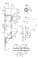
- Fig. 1 shows the automatic paper feed device according to the present invention.
- numeral 1 designates a slitter for slitting in half a web of paper 2 being fed from a printing unit. It comprises a drag roller 3 provided to extend at a right angle to the feed direction X of the web 2 and a slitter knife 5 mounted on a support member 4.
- the web 2 is adapted to be cut in half along its center line CL extending in the feed direction X when passing the slitter 1. It is thus cut into two webs of paper, i.e. a web 2S at the lefthand side or at the operating side and a web 2K at the righthand side or at the driving side. Before being slitted in half, the web 2 has its leading end 2A cut obliquely so that the pointed tip will be located at the operating side.
- the web 2 has a leader 7 in the form of a film stuck thereon near its pointed tip by means of a reinforcing tape 6 such as a kraft tape. Before being slitted, the web 2 is fed with its tip held by a paper feed rope 8 provided along a paper feed path.
- the paper feed rope 8 is provided to run through a guide pipe 9 having a suitable rigidity such as a conduit pipe and formed with a slit 9a along one side thereof so that it has a sectional shape of the letter C.
- the paper feed rope 8 is held by and between pairs of wheels 11 received in pairs of opposed cutouts 10 formed in the upper and lower sides of the guide pipe 9 so as to be fed in one direction by rotating the wheels 11.
- the paper feed rope 8 is provided at one side thereof with an arm 12 extending horizontally through the slit 9a formed in the guide pipe 9.
- the leader 7 is secured to the arm 12.
- Other parts numbered in Fig. 2 are coupling rings 13 and 14 and a drive shaft 15 for a driving means (not shown).
- a reinforcing tape 16 similar to the reinforcing tape 6 is stuck on the web of paper 2S at the operating side near its tip.
- Numerals 17 and 18 designate turnbars provided in a turnbar unit T so as to extend in parallel to each other at an angle of about 45 degrees with respect to the guide pipe 9. They are used to put the web 2K at the driving side and the web 2S at the operating side one upon the other.
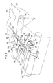
- Figs. 4 and 5 show the details of the turnbar unit T in which numeral 19 designates a guide pipe provided along a paper feed path for the web 2K at the driving side and extending from the area near the slitter 1 at its downstream side to the entrance to a folding unit F.
- the guide pipe 19 has the same construction as the guide pipe 9.
- a paper feed rope 20 extends therethrough and is normally in a stand-by state. It has its portion at the upstream side connected to a leader 23 (formed with a cutout 22) through an arm 21 as with the paper feed rope 8.
- Numeral 24 designates a sensor for detecting whether or not the leader 23 is at a predetermined position.
- Numeral 25 indicates a tape applicator provided under the leader 23 to stick the leader 23 on the tip 2K′ of the web 2K at the driving side being fed from upstream.
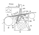
- Numeral 27 indicates a guide plate provided below the leader 23 and formed in substantially the center thereof with a cutout 28. Under the guide plate 27, there is provided a tape reel 30 upon which is mounted a roll of single-sided adhesive tape 29.
- a tape application roller 31 (Fig. 6) is mounted on the top end of an actuator 32A of a cylinder 32 so as to be movable up and down through the cutout 28 in the guide plate 27.
- a press roller 33 is mounted on the bottom of an actuator 34A of a cylinder 34 so as to be located over the guide plate 27 opposite to the roller 31 and be movable up and down.
- Guide members 35 and 36 are provided to guide the tape 29 mounted on the tape reel 30 into between the tape application roller 31 and the press roller 33.
- a tape cutter 37 is mounted on the end of an actuator 38A of a cylinder 38 so as to be movable to and fro.
- rollers 39 and 40 serve to guide the web of paper 2K at the driving side.
- the web of paper 2 is cut in half into the web 2S at the operating side and the web 2K at the driving side by the slitter 1. Since the web 2S at the operating side has its leading end secured to the leader 7 connected to the paper feed rope 8 through the arm 12, it is fed by the rope 8 toward the folding unit F through the paper feed path.
- the sensor 26 will detect the position of its end 2K′ and activate the cylinder 32 to raise the tape application roller 31 with the end of the tape 29 stuck thereto. At the same time, the sensor 26 will activate the cylinder 34 to lower the press roller 33. Thus the leader 23 and the end 2K′ of the web 2K will be pressed between the rollers 31 and 33 and joined together by the tape 29.
- the paper feed rope 20 for the web K at the driving side which have been kept at a stop, will begin to move downstream. This will cause the tape reel 30 to turn to unwind the tape 29, so that the tape 29 is put on the leader 23 over the entire length thereof and then on the web 2K at the driving side.
- the cylinder 38 will be activated to cut the tape 29 with the tape cutter 37.
- the web 2K at the driving side is connected to the paper feed rope 20 in the turnbar unit.
- the present invention there is no need of providing a plurality of slitter knives and controlling them one after another as in the prior art. Also, there is no need of providing a belt both at the operating side and the driving side throughout the machine from the paper feed unit to the folding unit as in the prior art. Thus, the construction is simpler and the production cost is lower. Also, the device according to the present invention is trouble-free and operates reliably because it includes a small number of parts.
Landscapes
- Engineering & Computer Science (AREA)
- Mechanical Engineering (AREA)
- Replacement Of Web Rolls (AREA)
- Folding Of Thin Sheet-Like Materials, Special Discharging Devices, And Others (AREA)
Applications Claiming Priority (2)
| Application Number | Priority Date | Filing Date | Title |
|---|---|---|---|
| JP107821/88 | 1988-08-15 | ||
| JP1988107821U JPH0739646Y2 (ja) | 1988-08-15 | 1988-08-15 | ターンバー部の自動紙通し装置 |
Publications (3)
| Publication Number | Publication Date |
|---|---|
| EP0355026A2 true EP0355026A2 (fr) | 1990-02-21 |
| EP0355026A3 EP0355026A3 (en) | 1990-06-27 |
| EP0355026B1 EP0355026B1 (fr) | 1993-03-10 |
Family
ID=14468892
Family Applications (1)
| Application Number | Title | Priority Date | Filing Date |
|---|---|---|---|
| EP89115013A Expired - Lifetime EP0355026B1 (fr) | 1988-08-15 | 1989-08-14 | Dispositif d'alimentation automatique de bande de papier |
Country Status (4)
| Country | Link |
|---|---|
| US (1) | US5078825A (fr) |
| EP (1) | EP0355026B1 (fr) |
| JP (1) | JPH0739646Y2 (fr) |
| DE (1) | DE68905263T2 (fr) |
Cited By (14)
| Publication number | Priority date | Publication date | Assignee | Title |
|---|---|---|---|---|
| EP0418903A2 (fr) * | 1989-09-20 | 1991-03-27 | Kabushiki Kaisha Tokyo Kikai Seisakusho | Dispositif d'introduction d'une bande de papier pour presse rotative |
| EP0425741A1 (fr) * | 1989-11-01 | 1991-05-08 | Hamada Printing Press Co. Ltd. | Dispositif d'alimentation de bande pour rotative |
| US5041234A (en) * | 1988-03-31 | 1991-08-20 | Lever Brothers Company, Division Of Conopco, Inc. | Transparent soap bars which may contain short chain monohydric alcohols, and a method of making the same |
| DE4213863A1 (de) * | 1991-04-30 | 1992-11-05 | Tokyo Kikai Seisakusho Ltd | Vorrichtung zum verbinden einer papierbahn mit einem papierbahn-einfaedelteil |
| EP0533042A1 (fr) * | 1991-09-14 | 1993-03-24 | MAN Roland Druckmaschinen AG | Dispositif pour enfiler des bandes dans les rotatives à imprimer à rouleaux |
| DE4202713A1 (de) * | 1992-01-31 | 1993-08-05 | Koenig & Bauer Ag | Fuehrung zum einziehen einer materialbahn in eine rollenrotationsdruckmaschine |
| US5275673A (en) * | 1991-04-11 | 1994-01-04 | Kabushiki Kaisha Tokyo Kikai Seisakusho | Method of and apparatus for connecting a paper web threading member with a paper web |
| DE4409693C1 (de) * | 1994-03-22 | 1995-09-21 | Roland Man Druckmasch | Vorrichtung zum Einziehen von Bedruckstoffbahnen über Wendestangen |
| EP1138482A1 (fr) * | 2000-03-30 | 2001-10-04 | Heidelberger Druckmaschinen Aktiengesellschaft | Dispositif d'engagement de la bande avec des stations de raccordement décentralisées |
| FR2806961A1 (fr) * | 2000-03-30 | 2001-10-05 | Heidelberger Druckmasch Ag | Dispositif d'introduction d'une bande a stations d'attache decentralisees |
| DE10043839A1 (de) * | 2000-09-06 | 2002-04-25 | Koenig & Bauer Ag | Vorrichtung und Verfahren zum An- und Abkuppeln einer Einrichtung zum Befestigen eines Anfanges einer Papierbahn an ein Zugmittel |
| US6553881B2 (en) | 2000-07-13 | 2003-04-29 | Heidelberger Druckmaschinen Ag | Configuration for introducing material webs into conveying paths of rotary printing machines |
| EP1454861A2 (fr) * | 1999-03-19 | 2004-09-08 | Koenig & Bauer Aktiengesellschaft | Dispositif pour transporter des bandes en papier |
| DE102010001146A1 (de) | 2010-01-22 | 2011-07-28 | KOENIG & BAUER Aktiengesellschaft, 97080 | Kettenschienen für Einziehketten und ein Verfahren zur Herstellung einer Kettenschiene |
Families Citing this family (5)
| Publication number | Priority date | Publication date | Assignee | Title |
|---|---|---|---|---|
| JP2590389B2 (ja) * | 1991-05-16 | 1997-03-12 | 株式会社 ロックウェル グラフィック システムズ ジャパン | 走行紙の補強方法及びその装置 |
| DE9409390U1 (de) * | 1994-06-10 | 1994-09-08 | Sächsisches Institut für die Druckindustrie GmbH, 04439 Engelsdorf | Bahneinzugsvorrichtung |
| DE102007039486B4 (de) * | 2007-08-21 | 2011-08-25 | manroland AG, 63075 | Einziehen einer Bedruckstoffbahn in eine Rollenrotationsdruckmaschine |
| US20110278390A1 (en) * | 2010-05-12 | 2011-11-17 | Armbruster Randy E | Media transport system turnover mechanism |
| JP6098586B2 (ja) | 2014-08-05 | 2017-03-22 | カシオ計算機株式会社 | 画像形成装置 |
Citations (1)
| Publication number | Priority date | Publication date | Assignee | Title |
|---|---|---|---|---|
| US4063505A (en) * | 1975-07-21 | 1977-12-20 | Ikegsi Iron Works, Ltd. | Papering apparatus in rotary printing press |
Family Cites Families (4)
| Publication number | Priority date | Publication date | Assignee | Title |
|---|---|---|---|---|
| JPS5516671U (fr) * | 1978-07-18 | 1980-02-01 | ||
| JPS5848351A (ja) * | 1981-09-18 | 1983-03-22 | Hitachi Maxell Ltd | 電池の製造法 |
| DE3237504C2 (de) * | 1982-10-09 | 1985-07-11 | Koenig & Bauer AG, 8700 Würzburg | Papierbahnführung in Rollenrotationsdruckmaschinen |
| US4725050A (en) * | 1986-07-22 | 1988-02-16 | Tokyo Kikai Seisakusho | Multi-section folding apparatus for rotary press |
-
1988
- 1988-08-15 JP JP1988107821U patent/JPH0739646Y2/ja not_active Expired - Lifetime
-
1989
- 1989-08-14 DE DE8989115013T patent/DE68905263T2/de not_active Expired - Fee Related
- 1989-08-14 EP EP89115013A patent/EP0355026B1/fr not_active Expired - Lifetime
-
1990
- 1990-05-14 US US07/522,463 patent/US5078825A/en not_active Expired - Lifetime
Patent Citations (1)
| Publication number | Priority date | Publication date | Assignee | Title |
|---|---|---|---|---|
| US4063505A (en) * | 1975-07-21 | 1977-12-20 | Ikegsi Iron Works, Ltd. | Papering apparatus in rotary printing press |
Cited By (22)
| Publication number | Priority date | Publication date | Assignee | Title |
|---|---|---|---|---|
| US5041234A (en) * | 1988-03-31 | 1991-08-20 | Lever Brothers Company, Division Of Conopco, Inc. | Transparent soap bars which may contain short chain monohydric alcohols, and a method of making the same |
| EP0418903A3 (en) * | 1989-09-20 | 1991-07-31 | Kabushiki Kaisha Tokyo Kikai Seisakusho | Paper web threading apparatus for rotary printing press |
| US5052295A (en) * | 1989-09-20 | 1991-10-01 | Kabushiki Kaisha Tokyo Kikai Seisakusho | Paper web threading apparatus for rotary printing press |
| EP0418903A2 (fr) * | 1989-09-20 | 1991-03-27 | Kabushiki Kaisha Tokyo Kikai Seisakusho | Dispositif d'introduction d'une bande de papier pour presse rotative |
| EP0425741A1 (fr) * | 1989-11-01 | 1991-05-08 | Hamada Printing Press Co. Ltd. | Dispositif d'alimentation de bande pour rotative |
| US5275673A (en) * | 1991-04-11 | 1994-01-04 | Kabushiki Kaisha Tokyo Kikai Seisakusho | Method of and apparatus for connecting a paper web threading member with a paper web |
| DE4213863A1 (de) * | 1991-04-30 | 1992-11-05 | Tokyo Kikai Seisakusho Ltd | Vorrichtung zum verbinden einer papierbahn mit einem papierbahn-einfaedelteil |
| DE4213863C2 (de) * | 1991-04-30 | 1994-10-13 | Tokyo Kikai Seisakusho Ltd | Vorrichtung zum Verbinden einer Papierbahn mit einem Papierbahn-Einfädelteil |
| US5255602A (en) * | 1991-09-14 | 1993-10-26 | Man Roland Druckmaschinen Ag | Apparatus for threading webs in rotary printing machines |
| EP0533042A1 (fr) * | 1991-09-14 | 1993-03-24 | MAN Roland Druckmaschinen AG | Dispositif pour enfiler des bandes dans les rotatives à imprimer à rouleaux |
| US5263414A (en) * | 1992-01-31 | 1993-11-23 | Koenig & Bauer Aktiengesellschaft | Material web guide assembly |
| DE4202713A1 (de) * | 1992-01-31 | 1993-08-05 | Koenig & Bauer Ag | Fuehrung zum einziehen einer materialbahn in eine rollenrotationsdruckmaschine |
| DE4409693C1 (de) * | 1994-03-22 | 1995-09-21 | Roland Man Druckmasch | Vorrichtung zum Einziehen von Bedruckstoffbahnen über Wendestangen |
| EP1454861A2 (fr) * | 1999-03-19 | 2004-09-08 | Koenig & Bauer Aktiengesellschaft | Dispositif pour transporter des bandes en papier |
| EP1454861A3 (fr) * | 1999-03-19 | 2004-10-27 | Koenig & Bauer Aktiengesellschaft | Dispositif pour transporter des bandes en papier |
| EP1138482A1 (fr) * | 2000-03-30 | 2001-10-04 | Heidelberger Druckmaschinen Aktiengesellschaft | Dispositif d'engagement de la bande avec des stations de raccordement décentralisées |
| FR2806961A1 (fr) * | 2000-03-30 | 2001-10-05 | Heidelberger Druckmasch Ag | Dispositif d'introduction d'une bande a stations d'attache decentralisees |
| US6553881B2 (en) | 2000-07-13 | 2003-04-29 | Heidelberger Druckmaschinen Ag | Configuration for introducing material webs into conveying paths of rotary printing machines |
| DE10043839C2 (de) * | 2000-09-06 | 2002-08-08 | Koenig & Bauer Ag | Vorrichtung und Verfahren zum An- und Abkuppeln einer Einrichtung zum Befestigen eines Anfanges einer Papierbahn an ein Zugmittel |
| DE10043839A1 (de) * | 2000-09-06 | 2002-04-25 | Koenig & Bauer Ag | Vorrichtung und Verfahren zum An- und Abkuppeln einer Einrichtung zum Befestigen eines Anfanges einer Papierbahn an ein Zugmittel |
| DE102010001146A1 (de) | 2010-01-22 | 2011-07-28 | KOENIG & BAUER Aktiengesellschaft, 97080 | Kettenschienen für Einziehketten und ein Verfahren zur Herstellung einer Kettenschiene |
| DE102010001146B4 (de) * | 2010-01-22 | 2015-01-15 | Koenig & Bauer Aktiengesellschaft | Kettenschiene für Einziehketten und ein Verfahren zur Herstellung einer Kettenschiene |
Also Published As
| Publication number | Publication date |
|---|---|
| DE68905263T2 (de) | 1993-06-17 |
| US5078825A (en) | 1992-01-07 |
| EP0355026A3 (en) | 1990-06-27 |
| JPH0229727U (fr) | 1990-02-26 |
| JPH0739646Y2 (ja) | 1995-09-13 |
| EP0355026B1 (fr) | 1993-03-10 |
| DE68905263D1 (de) | 1993-04-15 |
Similar Documents
| Publication | Publication Date | Title |
|---|---|---|
| EP0355026B1 (fr) | Dispositif d'alimentation automatique de bande de papier | |
| US4695005A (en) | Coreless winder for strips of pliable material | |
| US4543152A (en) | Apparatus for splicing successive web rolls to feed a web into a rotary press or the like | |
| US4922683A (en) | Shrink banding machine | |
| US5074178A (en) | Apparatus and method for cutting drawings from a web of sheet material | |
| EP2081831B1 (fr) | Machine permettant d'effectuer un enveloppement sous film perforé | |
| JPS6353094B2 (fr) | ||
| GB1569886A (en) | Splicing webs of sheet material | |
| SE451374B (sv) | Anordning for genomforande av en flygande vexling av rullar | |
| US5289669A (en) | Coreless winder and method of use | |
| US6189587B1 (en) | Automated tape splicing system | |
| EP0166884A1 (fr) | Procédé et dispositif pour relier des rouleaux de bandes de papier se succédant | |
| US5129294A (en) | Method of replacing and adjusting preprinted strip material on a manufacturing machine | |
| CN113978043A (zh) | 一种湿巾自动化生产线 | |
| US5605267A (en) | Apparatus for automatically feeding the end of a web of material | |
| US4189339A (en) | Method for providing sections of wrapping material having a strip of adhesive tape attached to an end portion thereof | |
| JP3584456B2 (ja) | 可撓性帯状材の接合方法及びその接合装置 | |
| KR910011356A (ko) | 아모르퍼스금속박의 슬리트 가공방법 및 장치 | |
| US6416012B1 (en) | Apparatuses and methods for cutting and spooling paper | |
| EP1648805B1 (fr) | Procede et appareil de raccordement de bandes | |
| EP1727755B1 (fr) | Dispositifs pour preparer une bobine formee d'une bande de materiau enroulee, pour changement de bobine automatique | |
| EP3490919B1 (fr) | Unité d'alimentation pour une machine de conversion de tissu pour convertir une bande de tissu à deux couches | |
| US4743335A (en) | Device for the continuous feeding of a ribbon shaped material to a processing machine | |
| JP3155773B2 (ja) | ラミネート枚葉紙の断裁装置 | |
| US5304275A (en) | Applying a reinforcement film to sheets |
Legal Events
| Date | Code | Title | Description |
|---|---|---|---|
| PUAI | Public reference made under article 153(3) epc to a published international application that has entered the european phase |
Free format text: ORIGINAL CODE: 0009012 |
|
| AK | Designated contracting states |
Kind code of ref document: A2 Designated state(s): DE FR GB |
|
| PUAL | Search report despatched |
Free format text: ORIGINAL CODE: 0009013 |
|
| AK | Designated contracting states |
Kind code of ref document: A3 Designated state(s): DE FR GB |
|
| 17P | Request for examination filed |
Effective date: 19900828 |
|
| 17Q | First examination report despatched |
Effective date: 19920525 |
|
| GRAA | (expected) grant |
Free format text: ORIGINAL CODE: 0009210 |
|
| AK | Designated contracting states |
Kind code of ref document: B1 Designated state(s): DE FR GB |
|
| REF | Corresponds to: |
Ref document number: 68905263 Country of ref document: DE Date of ref document: 19930415 |
|
| ET | Fr: translation filed | ||
| PLBE | No opposition filed within time limit |
Free format text: ORIGINAL CODE: 0009261 |
|
| STAA | Information on the status of an ep patent application or granted ep patent |
Free format text: STATUS: NO OPPOSITION FILED WITHIN TIME LIMIT |
|
| 26N | No opposition filed | ||
| REG | Reference to a national code |
Ref country code: GB Ref legal event code: IF02 |
|
| PGFP | Annual fee paid to national office [announced via postgrant information from national office to epo] |
Ref country code: GB Payment date: 20030721 Year of fee payment: 15 |
|
| PGFP | Annual fee paid to national office [announced via postgrant information from national office to epo] |
Ref country code: FR Payment date: 20030819 Year of fee payment: 15 |
|
| PGFP | Annual fee paid to national office [announced via postgrant information from national office to epo] |
Ref country code: DE Payment date: 20031022 Year of fee payment: 15 |
|
| PG25 | Lapsed in a contracting state [announced via postgrant information from national office to epo] |
Ref country code: GB Free format text: LAPSE BECAUSE OF NON-PAYMENT OF DUE FEES Effective date: 20040814 |
|
| PG25 | Lapsed in a contracting state [announced via postgrant information from national office to epo] |
Ref country code: DE Free format text: LAPSE BECAUSE OF NON-PAYMENT OF DUE FEES Effective date: 20050301 |
|
| GBPC | Gb: european patent ceased through non-payment of renewal fee |
Effective date: 20040814 |
|
| PG25 | Lapsed in a contracting state [announced via postgrant information from national office to epo] |
Ref country code: FR Free format text: LAPSE BECAUSE OF NON-PAYMENT OF DUE FEES Effective date: 20050429 |
|
| REG | Reference to a national code |
Ref country code: FR Ref legal event code: ST |