EP0353575A1 - Stopping device for a silver - Google Patents
Stopping device for a silver Download PDFInfo
- Publication number
- EP0353575A1 EP0353575A1 EP89113523A EP89113523A EP0353575A1 EP 0353575 A1 EP0353575 A1 EP 0353575A1 EP 89113523 A EP89113523 A EP 89113523A EP 89113523 A EP89113523 A EP 89113523A EP 0353575 A1 EP0353575 A1 EP 0353575A1
- Authority
- EP
- European Patent Office
- Prior art keywords
- roller
- rollers
- fiber
- pair
- sliver
- Prior art date
- Legal status (The legal status is an assumption and is not a legal conclusion. Google has not performed a legal analysis and makes no representation as to the accuracy of the status listed.)
- Granted
Links
Images


Classifications
-
- D—TEXTILES; PAPER
- D01—NATURAL OR MAN-MADE THREADS OR FIBRES; SPINNING
- D01H—SPINNING OR TWISTING
- D01H13/00—Other common constructional features, details or accessories
- D01H13/14—Warning or safety devices, e.g. automatic fault detectors, stop motions ; Monitoring the entanglement of slivers in drafting arrangements
- D01H13/16—Warning or safety devices, e.g. automatic fault detectors, stop motions ; Monitoring the entanglement of slivers in drafting arrangements responsive to reduction in material tension, failure of supply, or breakage, of material
- D01H13/18—Warning or safety devices, e.g. automatic fault detectors, stop motions ; Monitoring the entanglement of slivers in drafting arrangements responsive to reduction in material tension, failure of supply, or breakage, of material stopping supply only
- D01H13/188—Warning or safety devices, e.g. automatic fault detectors, stop motions ; Monitoring the entanglement of slivers in drafting arrangements responsive to reduction in material tension, failure of supply, or breakage, of material stopping supply only by cutting or clamping yarns or rovings
Definitions
- the invention relates to a match stop device for use in combination with the drafting system of a spinning machine e.g. a ring spinning machine or jet spinning machine.
- the fiber material to be spun in the individual spinning position is normally delivered to this spinning position via a drafting system, the drafting system comprising a plurality of pairs of rollers.
- the fiber material template can be present in the form of an untwisted band, for example a stretch band, or in the form of a slightly twisted roving (for example from a flyer).
- fuse indicates an elongated structure of fiber material, wel ches serves as a template for a spinning machine, regardless of whether this template is provided with a support twist or not.
- the fiber feed at this spinning position is advantageously interrupted before the last pair of rollers of the drafting system (called exit, export or delivery roller pair) in order to reduce the loss of material and the risk of winding around a delivery roller.
- exit, export or delivery roller pair the last pair of rollers of the drafting system
- the invention provides a drafting system with an input roller pair available for each spinning position, the one roller of the pair being set in operation by a drive about its own longitudinal axis and the revolutions of this first roller by contact between the rollers of the pair to the second (pressure -) roller are transferred.
- the second roller is only assigned to the relevant spinning position, while the first roller can also be present as a single roller per spinning position or in the form of a continuous cylinder that extends over several spinning positions.
- the invention also provides for each spinning position a fiber guiding element for removing contact between the rollers of the pair of input rollers of this spinning position.
- the pressure roller can be lifted off the driven roller to remove the contact.
- the invention is characterized in that the guide element is arranged for each spinning position in such a way that the force lifting off the pressure rollers is exerted against the surface of the roller, and the fuse is thereby clamped.
- the fiber guiding element is (e.g. a funnel or a thread condenser) and guides the fiber stream in normal operation and is pressed against the pressure roller of the pair of input rollers when the thread breaks, thereby lifting the contact between the rollers and at the same time holding the fuse against the outer surface of the pressure roller.
- Such a fiber guide element is preferably arranged on the input side of the pair of input rollers.
- the fiber guide element is preferably movable between a normal position and an operative position, the fiber guide element allowing contact between the input rollers in its normal position and canceling it in its operative position.
- the fiber guide element performs a rotary movement between the normal position and the operative position.
- the sliver clamping point ie the point at which the sliver is clamped between the fiber guide element and the pressure roller after the contact between the drafting rollers has been removed, is normally ge slightly offset from the normal nip line of the input roller pair around the circumference of the pressure roller.
- the pressure roller is moved to remove contact with the input roller on a path which is a substantially straight extension of a pressure roller radius running through the nip.
- the fiber guide element can be connected via a signal transmission system to a thread monitor assigned to the appropriate spinning position, so that in normal operation the switching of the fiber guide element is triggered by the thread monitor detecting a broken thread in the spinning position.
- an actuatable means can be provided to switch off the effect of the thread monitor when starting the machine if there is no thread in the spinning position at this time.
- the input cylinder EZ and the pressure roller DW form the input roller pair of a drafting system, not shown, on a spinning machine, not shown, for example. a ring spinning machine or a jet spinning machine.
- the input cylinder EZ extends over several spinning positions (possibly over an entire machine side, i.e. it is in the form of a so-called continuous cylinder).
- the printing roller DW is assigned to a single spinning position (not shown).
- the pressure roller DW is pressed against the input cylinder EZ in order to keep the jacket surfaces of the roller DW and the cylinder EZ in contact with one another along the clamping line KL.
- the clamping line KL preferably runs parallel to the longitudinal axis LAD of the printing roller DW and the longitudinal axis LAZ of the input cylinder EZ.
- a suitable drive causes the cylinder EZ (according to FIG. 1) to rotate clockwise about its own longitudinal axis LAZ.
- the contact between the printing roller DW and the input cylinder EZ transfers the revolutions of the cylinder to the printing roller, so that the latter (according to FIG. 1) is rotated counterclockwise around its own longitudinal axis LAD.
- a fuse not particularly indicated
- the pressure roller DW remains in the position shown in order to pull the material to be spun from the template, not shown, into the drafting system.
- the fiber feed should be interrupted, as close as possible to the pair of feed rollers. This invention enables such an interruption in a particularly simple way.
- a clamping element KE1 is moved in the direction of arrow P from a waiting position against the printing roller DW in order to form a clamping point KS by contact with the outer surface of the printing roller DW.
- the waiting position of the element KE1 is on the opposite side of the fiber stream FS from the pressure roller DW.
- the fiber stream is initially deflected slightly and then pinched off by the contact between the element KE1 and the pressure roller DW.
- the pressure roller DW is slightly lifted from the input cylinder EZ. Since the printing roller is no longer driven by the input cylinder EZ and at the same time is braked by the clamping element KE1, the printing roller stops immediately.
- the fiber flow FS continues to flow downstream from the clamping point KS1.
- the fibers thus supplied by the drafting system must be picked up and taken away by a suitable suction device (not shown).
- the fibers held at the clamping point KS1 remain ready for re-spinning.
- the clamping element KS1 can be moved back into the waiting position, the pressure roller DW being brought back into its operating position, ie in contact with the feed cylinder EZ, by the support arrangement.
- the nip KS1 is, as already mentioned, on the input side of the pair of insertion rollers, but this is not essential to the invention.
- a clamping element KE2 could be arranged on the output side of the pair of feed rollers in order to form a corresponding clamping point KS2 in the diverging space of this pair of rollers.
- the longitudinal axis LAD of the printing roller DW would preferably be moved along the web AB2 between the operating position and the raised position in order to remove the contact between the printing roller and the input cylinder EZ.
- the alternative solution on the input side of the pair of input rollers will normally be preferred.
- the pressure roller DW works together with a driven feed roller EW which is individually assigned to the corresponding spinning position (ie does not extend over several spinning positions).
- the fiber stream FS is guided from the template (not shown) via a guide element FE into the clamping line KL of the pair of feed rollers.
- the guide element FE is pivotally mounted about a pivot point DP and can be pivoted about the pivot point DP from a guide position (shown in FIG. 2) to an intermediate position (not shown) by a suitable means (not shown). In the latter position, an edge L on the front end of the guide element is in contact with the Print roller DW to form the nip KS.
- the printing roller DW is then lifted off the roller EW, the longitudinal axis LAD of the printing roller being able to follow either a straight path ABG or a curved path ABK.
- the clamping point KS is slightly offset in relation to the clamping line KL in the circumferential direction of the pressure roller DW, so that the fibers clamped at the point KS either lie in the clamping line KL when the pressure roller DW moves back or through the Input roller EW can be quickly fed back into the clamping line KL.
- the longitudinal axis LAD of the pressure roller is no longer arranged (as in FIG. 1) perpendicularly above the longitudinal axis LAZ of the input roller EW, but is offset in the direction of the fiber upstream to give the pressure roller a slight "overhang" with respect to the input roller To give EW.
- FIGS. 3 to 5 Such an arrangement is also shown in FIGS. 3 to 5.
- Figure 3 shows the feed roller pair EP, the middle roller pair MP and the delivery roller pair LP of a two-zone drafting system.
- the fiber material supplied by the drafting system is delivered to a spinning position SP, which is only indicated schematically, and there to a yarn G (FIG. 4) by working elements of the spinning position, not shown (for example by the spindle-ring rotor combination of a ring spinning machine or the suitable nozzle arrangement of a nozzle spinning machine or by combining a fiber collection device together with a mechanical false twister in an OE false twist machine).
- the fiber material to be spun is put into operation in the input rollers couple of EP passed through the guide channel 10 of a condenser K.
- this material is drawn into the drafting system from a template (not shown) (for example a spool or a can) through the pair of input rollers EP.
- the condenser K is rotatably mounted on a pin 12.
- the condenser K is equipped with a cantilever 14 which, at its end remote from the pin 12, cooperates with an actuating device BV described below.
- the device BV comprises a chamber 18 carried by the arm 14 and containing a piston 16.
- the piston 16 is connected via a piston rod 20 to a stationary part 22 of the machine frame (not shown in more detail).
- a compressed air line 24 opens into the end of the chamber 18 remote from the part 22.
- the arm (lever arm) 14 is pivoted counterclockwise around the pin 12 according to FIG. 3 to bring the output of the condenser K into contact with the pressure roller DW of the input roller pair EP.
- the compressed air works against a prestress exerted by a compression spring 26.
- the spring 26 is located between the chamber 18 and another stationary part 22A of the frame.
- the thread monitor FW triggers the supply of compressed air from a suitable source Q via the line 24 into the chamber 18 via a signal line 28 and via a compressed air valve M, which triggers the pivoting movement of the condenser K. .
- the drafting system temporarily delivers fiber material. This material is carried away by a suction AS arranged on the delivery roller pair LP. After the formation of the clamping point KS and the lifting of the pressure roller DW, the new introduction of fiber material from the template into the drafting system is interrupted. The material already present in the drafting system is passed on from the center roller pair MP and the delivery roller pair LP to the suction AS. The fibers held at the clamping point KS (FIG. 5), however, cannot participate in this fiber stream FS, so that the fiber stream is interrupted in the draft zone between the input roller pair EP and the middle roller pair MP. The fibers F remain "threaded" with the pair of input rollers EP.
- the valve M is readjusted in order to interrupt the compressed air supply from the source Q to the line 24 and to vent the chamber 18 via the line 24 and a line 32.
- This enables the return of the lever arm 14 and the condenser K into the operating position (FIGS. 3 and 4) under the biasing force exerted by the compression spring 26.
- the clamping line KL is formed again by restoring the contact between the pressure roller DW and the input roller EW and almost simultaneously the previously held fibers F are released again by the removal of the clamping point KS, which causes the new introduction of fiber material from the template into the drafting system to restore the fiber stream FS.
- the arrangement is accordingly self-threading.
- the vacuum at the suction AS can be simultaneously be interrupted with the new entry of the fiber feed so that the newly delivered fibers are now delivered to the provided spinning position SP.
- the suction AS can be connected again to a vacuum source, not shown, if the thread monitor FW detects a new thread break.
- the previously mentioned signal line 28 comprises a switch 34 which can be actuated by a push button D, a switch 36 which can be actuated by the thread monitor FW and a coil 38 which sets the valve M.
- the coil 38 therefore actuates the solenoid valve M so that compressed air from the source Q is conducted into the chamber 18. Accordingly, the condenser K is immediately moved from the operating position (FIG. 3) to the operative position (FIG. 5) in order to lift the pressure roller DW from the insertion roller EW and to clamp the fibers F which are still threaded with these rollers.
- the state of the main switch is shown on the top row of the signal diagram in FIG. 6, the state of the push button D on the second top row, the state of the thread monitor FW on the third top row and the state of the chamber 18 on the bottom row.
- the thread monitor FW determines the presence of this yarn G and opens the switch 36 (in FIG. 6, time T3). Shortly afterwards (at point T4) the push button D can be released again (e.g. by a suitable time relay, not shown) in order to close the switch 34 (FIG. 4).
- the overall arrangement has now reached the normal operating state and is ready to react to a possible thread break (in FIG. 6, time T5) with the opening of the switch 36 by the thread monitor FW.
- the starting process can be triggered again by actuating the push button D (in FIG. 6, time T6). Because the process when starting (after a thread break) corresponds exactly to the process of re-spinning (after the machine has been shut down), the process already described for re-spinning will not be repeated.
- the movable clamping element is formed as a fiber guide element (preferably as a sliver condenser), but this is not essential to the invention. It is also not necessary that the movement of the clamping element from its waiting position (in the preferred variant from the operating position of the condenser) into the operative position (clamping the fuse) is carried out by a pivoting movement. The same effect could be achieved by a linear movement of the clamping element.
- the preferred variant is particularly advantageous over the arrangement described in DOS 2952533, in which the number of work elements and the work paths are kept small, which enables a space-saving and simple arrangement.
- this invention achieves the advantage that the formation of the nip and the removal of contact between the insertion rollers occurs approximately simultaneously. This ensures that the separation of the fiber stream takes place after the formation (downstream of the) clamping point. However, since the clamping point KS is formed just in the vicinity of the clamping line KL, the retained fibers remain ready to start the sliver insertion.
- the pressure roller DW can be formed as a double roller unit, the rollers of one unit being assigned to respective adjacent spinning positions. There this arrangement for ring spinning is well known, it will not be explained here.
- the clamping forces exerted on the lateral surface of the pressure roller are also used to lift the pressure roller and thereby to remove contact between the rollers of the pair of input rollers.
- the clamping and lifting element counteracts a "grinding" (tangential) movement over the pressure roller (and the fuse) - both when lifting off and when resetting the pressure roller. An attempt is made to move the clamping element up to the normal clamping line of the pair of inlet rollers.
- the fuse is not subjected to any rubbing movement.
- the clamping element moves for clamping / lifting or for releasing / resetting in an approximately radial direction with respect to the pressure roller.
- the nip is slightly offset from the normal nip line in the circumferential direction of the pressure roller and is therefore accessible, despite a relatively short path of movement of the nip element, without substantial tangential movement of the nip element.
- a condenser enclosing the fuse preferably opens against the pressure roller in order to simplify the formation of a clamping edge on the condenser.
- the fiber guide as a clamping element, the latter can be in its "waiting" (fiber-guiding) position particularly close to the pressure roller, and thus to the nip.
Abstract
Tritt an der Liefervorrichtung für eine Faserlunte FS an einer Spinnmaschine ein Fadenbruch auf, dann wird die Druckwalze DW des Walzenpaares DW, EZ am Streckwerkausgang erfindungsgemäß von einem Faserführungselement KE1, das die Faserlunte in die Klemmenlinie der beiden Walzen führt und mit mindestens einer Kante radial zur zweiten Walze bewegbar ist, von der angetriebenen Walze abgehoben. Dadurch wird gleichzeitig eine Klemmstelle für die Faserlunte gebildet.If a thread break occurs on the delivery device for a fiber sliver FS on a spinning machine, then the pressure roller DW of the pair of rollers DW, EZ at the drafting device output is inventively provided by a fiber guiding element KE1, which guides the fiber sliver into the nip line of the two rollers and with at least one edge radially toward it second roller is movable, lifted from the driven roller. This also forms a nip for the fiber sliver.
Description
Die Erfindung bezieht sich auf eine Luntenstopvorrichtung zum Einsatz in Kombination mit dem Streckwerk einer Spinnmaschine z.B. einer Ringspinnmaschine oder Düsenspinnmaschine.The invention relates to a match stop device for use in combination with the drafting system of a spinning machine e.g. a ring spinning machine or jet spinning machine.
Beim Spinnen ohne Auflösen in einzelne Fasern wird das in der einzelnen Spinnposition zu verspinnende Fasermaterial normalerweise an diese Spinnposition über ein Streckwerk geliefert, wobei das Streckwerk eine Mehrzahl von Walzenpaaren umfasst. Dabei kann die Fasermaterialvorlage in der Form eines ungedrehten Bandes, z.B. eines Streckenbandes,oder in der Form eines leicht gedrehten Vorgarnes (z.B. vom Flyer) vorhanden sein. In dieser Beschreibung deutet der Ausdruck "Lunte" auf ein längliches Gebilde von Fasermaterial, wel ches als Vorlage für eine Spinnmaschine dient, gleichgültig ob diese Vorlage mit einem Stützdrall versehen ist oder nicht.In spinning without dissolving into individual fibers, the fiber material to be spun in the individual spinning position is normally delivered to this spinning position via a drafting system, the drafting system comprising a plurality of pairs of rollers. The fiber material template can be present in the form of an untwisted band, for example a stretch band, or in the form of a slightly twisted roving (for example from a flyer). In this description, the term "fuse" indicates an elongated structure of fiber material, wel ches serves as a template for a spinning machine, regardless of whether this template is provided with a support twist or not.
Beim Entstehen eines Fadenbruches in einer einzelnen Spinnposition wird vorteilhaft die Faserzufuhr an dieser Spinnposition vor dem letzten Walzenpaar des Streckwerkes (genannt Ausgang-, Ausfuhr- oder Lieferwalzenpaar) unterbrochen, um den Materialverlust und das Risiko eines Wickels um eine Lieferwalze zu vermindern. Zu diesem Zweck ist es schon bekannt:
- Das Eingangswalzenpaar des Streckwerkes beim Fadenbruch stillzusetzen und die Lunte zwischen den Walzen dieses Paares zu klemmen. Zum Neuanspinnen dieser Spinnposition ist es dann nur notwendig das Eingangwalzenpaar des Streckwerkes wieder in Gang zu setzen, so dass die vorher geklemmte Lunte wieder durch das Streckwerk befördert wird. Dazu ist es aber notwendig jedes Eingangswalzenpaar der Gesamtstreckwerkanordnung einzeln anzutreiben, was die Benützung eines durchgehenden Streckwerkzylinders (Ringspinnmaschine) verunmöglicht und aufwendige Schaltmittel zum Abkoppeln der individuellen Eingangswalzenpaare von einer gemeinsamen Antriebswelle erfordert.
- Es ist auch bekannt, beim Fadenbruch ein Klemmelement in den konvergierenden Raum auf der Eingangsseite des Eingangswalzenpaares derart zu bewegen, dass die Lunte zwischen dem Klemmelement und der einen oder der anderen Eingangswalze geklemmt wird. Die Selbsteinfädelung der Lunte in das Streckwerk ist aber dann beim Neuanspinnen nicht mehr gewährleistet, und es entsteht Reibung zwischen dem Klemm element und den Streckwerkswalzen solange der Fadenbruch noch nicht behoben worden ist.
- Es ist weiterhin bekannt (DOS 2952533), die obere (Druck-)Walze vom unteren (angetriebenen) durchgehenden Zylinder beim Fadenbruch abzuheben und die Lunte gegen die abgehobene (stillstehende) Walze festzuklemmen. Die Lunte bleibt somit mit dem Eingangswalzenpaar eingefädelt obwohl die Faserzufuhr an die Spinnposition unterbrochen worden ist. Beim Neuanspinnen muss die abgehobene Druckwalze wieder in Berührung mit dem Lieferzylinder gebracht und die Klemmwirkung aufgehoben werden. Die Anordnung ist aufwendig und die Koordination der verschiedenen Funktionen ist nicht einfach.When a thread break occurs in a single spinning position, the fiber feed at this spinning position is advantageously interrupted before the last pair of rollers of the drafting system (called exit, export or delivery roller pair) in order to reduce the loss of material and the risk of winding around a delivery roller. For this purpose it is already known:
- Stop the pair of input rollers of the drafting system when the thread breaks and clamp the fuse between the rollers of this pair. To re-spin this spinning position, it is then only necessary to start the pair of input rollers of the drafting system again, so that the previously clamped fuse is conveyed through the drafting system again. For this purpose, however, it is necessary to individually drive each pair of input rollers in the overall drafting arrangement, which makes the use of a continuous drafting cylinder (ring spinning machine) impossible and requires complex switching means for decoupling the individual input roller pairs from a common drive shaft.
- It is also known to move a clamping element in the converging space on the input side of the input roller pair in such a way that the fuse is clamped between the clamping element and one or the other input roller when the thread breaks. The self-threading of the fuse in the drafting system is then no longer guaranteed when re-spinning, and there is friction between the clamp element and the drafting rollers as long as the thread break has not yet been remedied.
- It is also known (DOS 2952533) to lift the upper (pressure) roller from the lower (driven) continuous cylinder when the thread breaks and to clamp the fuse against the lifted (stationary) roller. The fuse thus remains threaded with the pair of input rollers even though the fiber feed to the spinning position has been interrupted. When re-spinning, the raised printing roller must be brought back into contact with the delivery cylinder and the clamping effect must be released. The arrangement is complex and the coordination of the various functions is not easy.
Trotz dieser und anderer Vorschläge zur Verwirklichung eines Luntenstops, und trotz der offensichtlichen Vorteile, welche aus dem Einsatz eines solchen Luntenstops entstehen würden, hat sich bislang keine Lösung durchsetzen können.Despite these and other proposals for realizing a match stop, and despite the obvious advantages that would result from the use of such a match stop, no solution has so far been able to prevail.
Die Erfindung sieht ein Streckwerk mit einem pro Spinnposition vorhandenen Eingangswalzenpaares vor, wobei die eine Walze des Paares in Betrieb durch einen Antrieb um die eigene Längsachse in Rotation versetzt wird und die Umdrehungen dieser ersten Walze durch Berührung zwischen den Walzen des Paares an die zweite (Druck-)Walze übertragen werden. Dabei ist die zweite Walze nur der zutreffenden Spinnposition zugeordnet, während die erste Walze auch als eine Einzelwalze pro Spinnposition oder aber auch in der Form eines durchgehenden sich über mehrere Spinnpositionen erstreckenden Zylinders vorhanden sein kann.The invention provides a drafting system with an input roller pair available for each spinning position, the one roller of the pair being set in operation by a drive about its own longitudinal axis and the revolutions of this first roller by contact between the rollers of the pair to the second (pressure -) roller are transferred. The second roller is only assigned to the relevant spinning position, while the first roller can also be present as a single roller per spinning position or in the form of a continuous cylinder that extends over several spinning positions.
Die Erfindung sieht ausserdem für jede Spinnposition ein Faserführungselement zum Aufheben der Berührung zwischen den Walzen des Eingangswalzenpaares dieser Spinnposition vor. Dazu kann die Druckwalze zum Aufheben der Berührung von der angetriebenen Walze abgehoben werden.The invention also provides for each spinning position a fiber guiding element for removing contact between the rollers of the pair of input rollers of this spinning position. For this purpose, the pressure roller can be lifted off the driven roller to remove the contact.
Die Erfindung ist dadurch gekennzeichnet, dass für jede Spinnposition das Führungselement derart angeordnet ist, dass die die Druckwalzen abhebende Kraft gegen die Walzenmantelfläche ausgeübt wird, und dass die Lunte dadurch geklemmt wird. Das Faserführungselement ist (z.B. ein Trichter oder ein Fadenkondensor) und führt im normalen Betrieb den Faserstrom und wird beim Fadenbruch gegen die Druckwalze des Eingangswalzenpaares gedrückt, um dadurch die Berührung zwischen den Walzen aufzuheben und gleichzeitig die Lunte gegen die Mantelfläche der Druckwalze festzuhalten. Ein solches Faserführungselement ist vorzugsweise auf der Eingangsseite des Eingangswalzenpaares angeordnet.The invention is characterized in that the guide element is arranged for each spinning position in such a way that the force lifting off the pressure rollers is exerted against the surface of the roller, and the fuse is thereby clamped. The fiber guiding element is (e.g. a funnel or a thread condenser) and guides the fiber stream in normal operation and is pressed against the pressure roller of the pair of input rollers when the thread breaks, thereby lifting the contact between the rollers and at the same time holding the fuse against the outer surface of the pressure roller. Such a fiber guide element is preferably arranged on the input side of the pair of input rollers.
Das Faserführungselement ist vorzugsweise zwischen einer normalen Stellung und einer operativen Stellung bewegbar, wobei das Faserführungselement die Berührung zwischen den Eingangswalzen in seiner normalen Stellung ermöglicht und in seiner operativen Stellung aufhebt. In einer bevorzugten Variante führt das Faserführungselement eine Drehbewegung zwischen der normalen Stellung und der operativen Stellung aus.The fiber guide element is preferably movable between a normal position and an operative position, the fiber guide element allowing contact between the input rollers in its normal position and canceling it in its operative position. In a preferred variant, the fiber guide element performs a rotary movement between the normal position and the operative position.
Die Luntenklemmstelle, d.h. die Stelle an welcher die Lunte zwischen dem Faserführungselement und der Druckwalze nach der Aufhebung der Berührung zwischen den Streckwerkswalzen geklemmt wird, ist normalerweise ge genüber der normalen Klemmlinie des Eingangswalzenpaares leicht um den Umfang der Druckwalze versetzt. Dabei wird die Druckwalze zur Aufhebung der Berührung mit der Eingangswalze auf einer Bahn bewegt, die eine im wesentlichen geradlinig Verlängerung eines durch die Klemmstelle verlaufenden Druckwalzenradius darstellt.The sliver clamping point, ie the point at which the sliver is clamped between the fiber guide element and the pressure roller after the contact between the drafting rollers has been removed, is normally ge slightly offset from the normal nip line of the input roller pair around the circumference of the pressure roller. The pressure roller is moved to remove contact with the input roller on a path which is a substantially straight extension of a pressure roller radius running through the nip.
Das Faserführungselement kann über ein Signalübertragungssystem mit einem der zutreffenden Spinnposition zugeordneten Fadenwächter verbunden werden, so dass im Normalbetrieb das Schalten des Faserführungselementes durch das Feststellen eines Fadenbruches der Spinnposition vom Fadenwächter ausgelöst wird. Es kann zusätzlich ein betätigbares Mittel vorgesehen werden, um die Wirkung des Fadenwächters beim Anfahren der Maschine auszuschalten, falls zu dieser Zeit kein Faden in der Spinnposition vorhanden ist.The fiber guide element can be connected via a signal transmission system to a thread monitor assigned to the appropriate spinning position, so that in normal operation the switching of the fiber guide element is triggered by the thread monitor detecting a broken thread in the spinning position. In addition, an actuatable means can be provided to switch off the effect of the thread monitor when starting the machine if there is no thread in the spinning position at this time.
Als Beispiele werden nun verschiedene Ausführungen dieser Erfindung anhand der schematischen Darstellungen in den Figuren der Zeichnungen näher erläutert werden. Es zeigt:
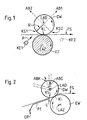
- Fig. 1 im Querschnitt das Eingangswalzenpaar eines Streckwerkes mit verschiedenen Möglichkeiten zur Realisierung des Erfindungsprinzips,
- Fig. 2 eine konstruktiv vorteilhafte Variante eines Prinzipes gemäss Fig. 1,
- Fig. 3 eine praktische Ausführung gemäss der Anordnung der Fig. 2,
- Fig. 4 die Anordnung von Fig. 3 mit einem geänderten Zustand des Signalsystems,
- Fig. 5 die Anordnung der Figuren 3 und 4 nach Aufhebung der Berühung zwischen den Eingangswalzen des Streckwerkes,
- Fig. 6 ein Schema zur Erklärung des Signalsystems für eine Ausführung gemäss den Figuren 3 bis 5.
- 1 in cross section the pair of input rollers of a drafting system with different possibilities for realizing the principle of the invention,
- 2 shows a constructively advantageous variant of a principle according to FIG. 1,
- 3 shows a practical embodiment according to the arrangement of FIG. 2,
- Fig. 4 shows the arrangement of Fig. 3 with a changed state of the signal system,
- 5 shows the arrangement of FIGS. 3 and 4 after lifting the contact between the input rollers of the drafting system,
- 6 shows a diagram for explaining the signal system for an embodiment according to FIGS. 3 to 5.
In Fig. 1 bilden der Eingangszylinder EZ und die Druckwalze DW das Eingangswalzenpaar eines nicht weiter dargestellten Streckwerkes auf einer nicht gezeigten Spinnmaschine, z.Bsp. einer Ringspinnmaschine oder einer Düsenspinnmaschine. Der Eingangszylinder EZ erstreckt sich über mehrere Spinnpositionen (möglicherweise über eine ganze Maschinenseite, d.h. ist in der Form eines sogenannten durchgehenden Zylinders). Die Druckwalze DW hingegen ist einer Einzelspinnposition (nicht gezeigt) zugeordnet. Im normalen Betrieb ist die Druckwalze DW gegen den Eingangszylinder EZ gedrückt, um die Manteloberflächen der Walze DW und des Zylinders EZ miteinander entlang der Klemmlinie KL in Berührung zu halten. Die Klemmlinie KL verläuft vorzugsweise parallel zur Längsachse LAD der Druckwalze DW und Längsachse LAZ des Eingangszylinders EZ.In Fig. 1, the input cylinder EZ and the pressure roller DW form the input roller pair of a drafting system, not shown, on a spinning machine, not shown, for example. a ring spinning machine or a jet spinning machine. The input cylinder EZ extends over several spinning positions (possibly over an entire machine side, i.e. it is in the form of a so-called continuous cylinder). The printing roller DW, however, is assigned to a single spinning position (not shown). In normal operation, the pressure roller DW is pressed against the input cylinder EZ in order to keep the jacket surfaces of the roller DW and the cylinder EZ in contact with one another along the clamping line KL. The clamping line KL preferably runs parallel to the longitudinal axis LAD of the printing roller DW and the longitudinal axis LAZ of the input cylinder EZ.
Durch einen geeigneten Antrieb (nicht gezeigt) wird der Zylinder EZ (gemäss Fig. 1) im Uhrzeigersinn in Rotation um die eigene Längsachse LAZ versetzt. Durch die Berührung zwischen der Druckwalze DW und dem Eingangszylinder EZ werden die Umdrehungen des Zylinders auf die Druckwalze übertragen, so dass letztere (gemäss Fig. 1) gegen den Uhrzeigersinn um die eigene Längsachse LAD in Rotation versetzt wird. Eine Lunte, nicht besonders angedeutet) kann in den konvergierenden Raum auf der Eingangsseite des Einzugswalzenpaares bis zur Klemmlinie KL eingeführt werden und wird beim angetriebenen Einzugszylinder EZ in das Streckwerk eingezogen, um einen Faserstrom FS durch das Streckwerk zu erzeugen. Da die übrigen Streckwerkelemente für diese Erfindung keine Bedeutung haben, sind sie aus dem Prinzipschema der Fig. 1 (und der Fig. 2) ausgelassen worden, um sich auf die wesentlichen Elemente konzentrieren zu können.A suitable drive (not shown) causes the cylinder EZ (according to FIG. 1) to rotate clockwise about its own longitudinal axis LAZ. The contact between the printing roller DW and the input cylinder EZ transfers the revolutions of the cylinder to the printing roller, so that the latter (according to FIG. 1) is rotated counterclockwise around its own longitudinal axis LAD. A fuse, not particularly indicated) can be introduced into the converging space on the input side of the pair of feed rollers up to the clamping line KL and is drawn into the drafting system in the driven feed cylinder EZ in order to generate a fiber flow FS through the drafting system. Since the other drafting elements have no significance for this invention, they have been omitted from the basic diagram of FIG. 1 (and FIG. 2) in order to be able to concentrate on the essential elements.
Solange die nicht gezeigten Arbeitselemente der Spinnposition normal arbeiten, um das vom Streckwerk gelieferte Fasermaterial zu einem Garn zu verarbeiten, bleibt die Druckwalze DW in der gezeigten Stellung, um das zu verspinnende Material aus der nicht gezeigten Vorlage in das Streckwerk zu ziehen. Falls aber ein Fadenbruch in dieser Spinnposition aus irgendwelchen Gründen vorkommt, sollte die Faserzufuhr unterbrochen werden und zwar so nahe wie möglich an dem Einzugswalzenpaar. Diese Erfindung ermöglicht eine solche Unterbrechung auf eine besonders einfache Weise.As long as the working elements of the spinning position, not shown, work normally to process the fiber material supplied by the drafting system into a yarn, the pressure roller DW remains in the position shown in order to pull the material to be spun from the template, not shown, into the drafting system. However, if a thread break occurs in this spinning position for any reason, the fiber feed should be interrupted, as close as possible to the pair of feed rollers. This invention enables such an interruption in a particularly simple way.
In einer ersten Variante wird ein Klemmelement KE1 in Richtung des Pfeils P aus einer Warteposition gegen die Druckwalze DW bewegt, um durch Berührung mit der Mantelfläche der Druckwalze DW eine Klemmstelle KS zu bilden. Die Warteposition des Elementes KE1 befindet sich auf der entgegengesetzten Seite des Faserstromes FS von der Druckwalze DW. Durch die Bewegung des Elementes KE1 quer zum Faserstrom FS bis zur Klemmstelle KS1 wird der Faserstrom vorerst leicht umgelenkt und dann durch die Berührung zwischen dem Element KE1 und der Druckwalze DW abgeklemmt. Durch eine Weiterbewe gung des Elementes KE1 in der gleichen Richtung wird die Druckwalze DW vom Eingangszylinder EZ leicht abgehoben. Da die Druckwalze nicht mehr vom Eingangszylinder EZ angetrieben wird und gleichzeitig vom Klemmelement KE1 gebremst wird, bleibt die Druckwalze augenblicklich stehen.In a first variant, a clamping element KE1 is moved in the direction of arrow P from a waiting position against the printing roller DW in order to form a clamping point KS by contact with the outer surface of the printing roller DW. The waiting position of the element KE1 is on the opposite side of the fiber stream FS from the pressure roller DW. By moving the element KE1 transversely to the fiber stream FS up to the clamping point KS1, the fiber stream is initially deflected slightly and then pinched off by the contact between the element KE1 and the pressure roller DW. By moving on the element KE1 in the same direction, the pressure roller DW is slightly lifted from the input cylinder EZ. Since the printing roller is no longer driven by the input cylinder EZ and at the same time is braked by the clamping element KE1, the printing roller stops immediately.
Im Laufe der Bewegung zwischen der normalen Betriebsstellung (Fig. 1) und der abgehobenen Stellung der Druckwalze DW folgt die Längsachse LAD dieser Walze eine Bahn AB1 (gestrichtelt) welche eine Verlängerung des durch die Klemmstelle KS1 verlaufenden Druckwalzenradius R darstellt. Die nicht gezeigte Traganordnung für die Druckwalze DW muss entsprechend ausgeführt werden, um diese Bewegung zu ermöglichen.In the course of the movement between the normal operating position (FIG. 1) and the raised position of the pressure roller DW, the longitudinal axis LAD of this roller follows a path AB1 (dashed line) which represents an extension of the pressure roller radius R running through the nip point KS1. The support arrangement (not shown) for the printing roller DW must be designed accordingly to enable this movement.
Da die nicht gezeigten nachgeschalteten Streckwerkwalzenpaare von dieser Erfindung unbeeinflusst bleiben, fliesst vorläufig der Faserstrom FS stromabwärts von der Klemmstelle KS1 weiter. Die somit vom Streckwerk gelieferten Fasern müssen von einer geeigneten Absaugvorrichtung (nicht gezeigt) aufgenommen und weggeführt werden. Die an der Klemmstelle KS1 festgehaltenen Fasern bleiben zum Neuanspinnen bereit. Wenn der Fadenbruch behoben worden ist, kann das Klemmelement KS1 zurück in die Warteposition bewegt werden, wobei die Druckwalze DW durch die Traganordnung zurück in ihre Betriebsstellung, d.h. in Berührung mit dem Einzugszylinder EZ, gebracht wird. Sobald die Klemmlinie KL wieder gebildet wird, werden die Fasern an der Klemmstelle KS1 vom Klemmelement KE1 freigegeben, wobei diese Fasern entweder schon in der neu gebildeten Klemmlinie KL oder in dem konvergierenden Raum auf der Eingangsseite des Einführwalzenpaares liegen. Im letzteren Fall werden diese Fasern sofort vom Ein gangszylinder EZ in die Klemmlinie KL befördert so die nun freigegebene Lunte wieder in das Streckwerk eingezogen wird. Das System ist somit selbst einfädelnd.Since the downstream drafting roller pairs, not shown, remain unaffected by this invention, the fiber flow FS continues to flow downstream from the clamping point KS1. The fibers thus supplied by the drafting system must be picked up and taken away by a suitable suction device (not shown). The fibers held at the clamping point KS1 remain ready for re-spinning. When the thread break has been remedied, the clamping element KS1 can be moved back into the waiting position, the pressure roller DW being brought back into its operating position, ie in contact with the feed cylinder EZ, by the support arrangement. As soon as the clamping line KL is formed again, the fibers at the clamping point KS1 are released by the clamping element KE1, these fibers either lying in the newly formed clamping line KL or in the converging space on the input side of the pair of insertion rollers. In the latter case, these fibers immediately become one gear cylinder EZ in the clamping line KL thus transports the now released fuse into the drafting system. The system is therefore self-threading.
Die Klemmstelle KS1 ist, wie schon erwähnt, auf der Eingangsseite des Einführwalzenpaares, was aber nicht erfindungswesentlich ist. Es könnte ein Klemmelement KE2 auf der Ausgangsseite des Einzugswalzenpaares angeordnet werden, um eine entsprechende Klemmstelle KS2 im divergierenden Raum dieses Walzenpaares zu bilden. In diesem Fall wäre die Längsachse LAD der Druckwalze DW vorzugsweise die Bahn AB2 entlang zwischen der Betriebsstellung und der abgehobenen Stellung zu bewegen, um die Berührung zwischen der Druckwalze und dem Eingangszylinder EZ aufzuheben. Aus Platzgründen wird man aber normalerweise die Alternativlösung auf der Eingangsseite des Eingangswalzenpaares den Vorzug geben.The nip KS1 is, as already mentioned, on the input side of the pair of insertion rollers, but this is not essential to the invention. A clamping element KE2 could be arranged on the output side of the pair of feed rollers in order to form a corresponding clamping point KS2 in the diverging space of this pair of rollers. In this case, the longitudinal axis LAD of the printing roller DW would preferably be moved along the web AB2 between the operating position and the raised position in order to remove the contact between the printing roller and the input cylinder EZ. For reasons of space, however, the alternative solution on the input side of the pair of input rollers will normally be preferred.
Fig. 2 zeigt eine weitere Variante des bevorzugten Prinzips. In diesem Fall arbeitet die Druckwalze DW mit einer angetriebenen Einzugswalze EW zusammen, welche individuell der entsprechenden Spinnposition zugeordnet ist (d.h. sich nicht über mehrere Spinnpositionen erstreckt). Der Faserstrom FS wird aus der nicht gezeigten Vorlage über einem Führungselement FE in die Klemmlinie KL des Einzugswalzenpaares geführt. Das Führungselement FE ist schwenkbar um einen Drehpunkt DP montiert und kann durch ein geeignetes Mittel (nicht gezeigt) um den Drehpunkt DP aus einer Führungsstellung (in Fig. 2 gezeigt) in einer Zwischenstellung (nicht gezeigt) geschwenkt werden. In der letzteren Stellung steht eine Kante L auf dem vorderen Ende des Führungselementes in Berührung mit der Druckwalze DW, um die Klemmstelle KS zu bilden. Durch die Weiterbewegung des Elementes FE, wird die Druckwalze DW dann von der Walze EW abgehoben, wobei die Längsachse LAD der Druckwalze entweder eine gradlinige Bahn ABG oder eine krumme Bahn ABK folgen kann.2 shows a further variant of the preferred principle. In this case, the pressure roller DW works together with a driven feed roller EW which is individually assigned to the corresponding spinning position (ie does not extend over several spinning positions). The fiber stream FS is guided from the template (not shown) via a guide element FE into the clamping line KL of the pair of feed rollers. The guide element FE is pivotally mounted about a pivot point DP and can be pivoted about the pivot point DP from a guide position (shown in FIG. 2) to an intermediate position (not shown) by a suitable means (not shown). In the latter position, an edge L on the front end of the guide element is in contact with the Print roller DW to form the nip KS. As a result of the further movement of the element FE, the printing roller DW is then lifted off the roller EW, the longitudinal axis LAD of the printing roller being able to follow either a straight path ABG or a curved path ABK.
Wie im Fall der Anordnung der Figur 1 ist die Klemmstelle KS gegenüber der Klemmlinie KL in der Umfangsrichtung der Druckwalze DW leicht versetzt, so dass die an der Stelle KS geklemmten Fasern bei der Rückbewegung der Druckwalze DW entweder schon in der Klemmlinie KL liegen oder durch die Eingangswalze EW schnell in die Klemmlinie KL wieder geführt werden können. Um die Konstruktion zu vereinfachen, ist die Längsachse LAD der Druckwalze nicht mehr (wie in der Fig. 1) senkrecht oberhalb der Längsachse LAZ der Eingangswalze EW angeordnet, sondern in der Richtung faserstromaufwärts versetzt, um die Druckwalze einen leichten "Ueberhang" gegenüber der Eingangswalze EW zu geben. Eine solche Anordnung ist auch in den Figuren 3 bis 5 gezeigt.As in the case of the arrangement in FIG. 1, the clamping point KS is slightly offset in relation to the clamping line KL in the circumferential direction of the pressure roller DW, so that the fibers clamped at the point KS either lie in the clamping line KL when the pressure roller DW moves back or through the Input roller EW can be quickly fed back into the clamping line KL. In order to simplify the construction, the longitudinal axis LAD of the pressure roller is no longer arranged (as in FIG. 1) perpendicularly above the longitudinal axis LAZ of the input roller EW, but is offset in the direction of the fiber upstream to give the pressure roller a slight "overhang" with respect to the input roller To give EW. Such an arrangement is also shown in FIGS. 3 to 5.
Figur 3 zeigt das Einzugswalzenpaar EP, das Mittelwalzenpaar MP und das Lieferwalzenpaar LP eines Zweizonenstreckwerkes. Das vom Streckwerk gelieferte Fasermaterial wird an eine nur schematisch angedeutete Spinnposition SP abgegeben und da zu einem Garn G (Fig. 4) durch nicht dargestellte Arbeitselemente der Spinnposition (z.B. durch die Spindel-Ring-Läufer Kombination einer Ringspinnmaschine oder die geeigneten Düsenanordnung einer Düsenspinnmaschine oder durch die Kombination einer Fasersammelvorrichtung zusammen mit einem mechanischen Falschdrallgeber in einer OE-Falschdrallmaschine) verarbeitet. Das zu verspinnende Fasermaterial wird in Betrieb in das Eingangswalzen paar EP über den Führungskanal 10 eines Kondensors K geleitet. Wie schon erwähnt wird dieses Material aus einer nicht gezeichneten Vorlage (z.B. einer Spule oder einer Kanne) durch das Eingangswalzenpaar EP in das Streckwerk eingezogen.Figure 3 shows the feed roller pair EP, the middle roller pair MP and the delivery roller pair LP of a two-zone drafting system. The fiber material supplied by the drafting system is delivered to a spinning position SP, which is only indicated schematically, and there to a yarn G (FIG. 4) by working elements of the spinning position, not shown (for example by the spindle-ring rotor combination of a ring spinning machine or the suitable nozzle arrangement of a nozzle spinning machine or by combining a fiber collection device together with a mechanical false twister in an OE false twist machine). The fiber material to be spun is put into operation in the input rollers couple of EP passed through the
Gemäss dem in Fig. 2 skizzierten Prinzip ist der Kondensor K drehbar auf einem Stift 12 montiert. Ausserdem ist der Kondensor K mit einem Ausleger 14 ausgestattet, der an seinem vom Stift 12 entfernten Ende mit einer nachfolgend beschriebenen Betätigungsvorrichtung BV zusammenarbeitet.According to the principle outlined in FIG. 2, the condenser K is rotatably mounted on a
Die Vorrichtung BV umfasst eine vom Arm 14 getragenen, einen Kolben 16 beinhaltenden, Kammer 18. Der Kolben 16 ist über eine Kolbenstange 20 mit einem stationären Teil 22 des nicht näher gezeigten Maschinengestells verbunden. Eine Druckluftleitung 24 mündet in das vom Teil 22 entfernte Ende der Kammer 18. Bei der Zufuhr von Luft mit einem geeigneten Druck über die Leitung 24 in die Kammer 18 wird der Ausleger (Hebelarm) 14 gemäss Fig. 3 im Gegenuhrzeigersinn um den Stift 12 geschwenkt, um den Ausgang des Kondensors K in Berührung mit der Druckwalze DW des Eingangswalzenpaares EP zu bringen. Dabei arbeitet die Druckluft gegen eine von einer Druckfeder 26 ausgeübten Vorspannung. Die Feder 26 befindet sich zwischen der Kammer 18 und einem weiteren stationären Teil 22A des Gestells. Beim Fehlen der Druckluftzufuhr hingegen wird der Hebelarm 14 und Kondensor K in einer normalen oder Betriebsstellung (Fig. 3 und 4) durch die Druckfeder 26 gehalten. In dieser Betriebsstellung mündet der Kondensor K (bzw. sein Kanal 10) in dem konvergierenden Raum auf der Eingangsseite des Einzugswalzenpaares EP ohne die Druckwalze DW zu berühren, so dass der Faserstrom FS (Fig. 4) unbehindert durch das Streckwerk fliessen kann.The device BV comprises a
In der normalen oder Betriebsstellung des Kondensors K liegt der Kolben 16 am vom Teil 22 entfernten Ende der Kammer 18 (Fig. 3 und 4). Am Schluss der von der Druckluft hervorgerufenen Schwenkbewegung des Kondensors K liegt der Kolben 16 an dem Teil 22 zugewandten Ende der Kammer 18 (Fig. 5). Die nicht näher gezeichnete Verbindung zwischen der Kolbenstange 20 und dem Teil 22 muss derart gestaltet sein, dass sie die notwendige Schwenkbewegung des Auslegers 14 ermöglicht. Im Lauf dieser Bewegung aus der Betriebsstellung (Fig. 4) in die operative Stellung (Fig. 5) bildet die vorher erwähnte Kante L (siehe auch Fig. 2) eine Klemmstelle KS mit der Druckwalze DW, wobei die Bildung dieser Klemmstelle KS vor der Vollendung der erwähnten Schwenkbewegung stattfindet. Durch die weitere Schwenkbewegung des Kondensors nach der Bildung der Klemmstelle KS wird die Druckwalze DW von der Eingangswalze EW abgehoben. Die die Klemmlinie KL (Fig. 3) bildende Berührung zwischen der Druckwalze DW und der Eingangswalze EW wird somit aufgehoben. In Betrieb, solange das Fasermaterial FS von der Spinnposition SP zu einem Garn G verarbeitet wird, bleibt die Kammer 18 ohne Druckluft. Die Herstellung eines Garnes G in der Spinnposition SP wird ständig von einem Fadenwächter FW überwacht. Bei einer Unterbrechung der Garnherstellung in dieser Spinnposition, löst der Fadenwächter FW über eine Signalleitung 28 und über einen darauf reagierenden Druckluftventil M die Zufuhr von Druckluft aus einer geeigneten Quelle Q über die Leitung 24 in die Kammer 18 aus, was die Schwenkbewegung des Kondensors K auslöst.In the normal or operating position of the condenser K, the
Nach der Entstehung eines Fadenbruches, liefert das Streckwerk vorläufig Fasermaterial weiter. Dieses Material wird von einer am Lieferwalzenpaar LP angeordneten Absaugung AS weggeführt. Nach der Bildung der Klemmstelle KS und der Abhebung der Druckwalze DW, wird die Neueinfuhr von Fasermaterial aus der Vorlage in das Streckwerk unterbrochen. Das im Streckwerk schon vorhandene Material wird vom Mittelwalzenpaar MP und Lieferwalzenpaar LP an die Absaugung AS weitergeführt. Die an der Klemmstelle KS festgehaltenen Fasern (Fig. 5) können aber an diesem Faserstrom FS nicht teilnehmen, so dass der Faserstrom im Vorverzugsfeld zwischen dem Eingangswalzenpaar EP und dem Mittelwalzenpaar MP unterbrochen wird. Dabei bleiben die Fasern F mit dem Eingangswalzenpaar EP "eingefädelt".After a thread break occurs, the drafting system temporarily delivers fiber material. This material is carried away by a suction AS arranged on the delivery roller pair LP. After the formation of the clamping point KS and the lifting of the pressure roller DW, the new introduction of fiber material from the template into the drafting system is interrupted. The material already present in the drafting system is passed on from the center roller pair MP and the delivery roller pair LP to the suction AS. The fibers held at the clamping point KS (FIG. 5), however, cannot participate in this fiber stream FS, so that the fiber stream is interrupted in the draft zone between the input roller pair EP and the middle roller pair MP. The fibers F remain "threaded" with the pair of input rollers EP.
Beim Beheben des Fadenbruches wird das Ventil M neu eingestellt, um die Druckluftzufuhr von der Quelle Q an die Leitung 24 zu unterbrechen und die Kammer 18 über die Leitung 24 und einer Leitung 32 zu entlüften. Dadurch wird die Rückkehr des Hebelarms 14 und Kondensors K in die Betriebsstellung (Fig. 3 und 4) unter der von Druckfeder 26 ausgeübten Vorspannungskraft ermöglicht. Dadurch wird die Klemmlinie KL durch Wiederherstellung der Berührung zwischen der Druckwalze DW und der Eingangswalze EW wieder gebildet und fast gleichzeitig die vorher festgehaltenen Fasern F durch die Aufhebung der Klemmstelle KS wieder freigegeben, was die Neueinfuhr von Fasermaterials aus der Vorlage in das Streckwerk bewirkt, um den Faserstrom FS wieder herzustellen. Die Anordnung ist dementsprechend selbsteinfädelnd.When the thread break is eliminated, the valve M is readjusted in order to interrupt the compressed air supply from the source Q to the
Der Unterdruck an der Absaugung AS kann gleichzeitig mit dem Neueintreten der Faserzufuhr unterbrochen werden, so dass die neu gelieferten Fasern nun an die bereitgestellte Spinnposition SP abgegeben wird. Die Absaugung AS kann nochmals mit einer nicht gezeichneten Unterdruckquelle verbunden werden, wenn der Fadenwächter FW einen neuen Fadenbruch feststellt.The vacuum at the suction AS can be simultaneously be interrupted with the new entry of the fiber feed so that the newly delivered fibers are now delivered to the provided spinning position SP. The suction AS can be connected again to a vacuum source, not shown, if the thread monitor FW detects a new thread break.
Die vorher erwähnte Signalleitung 28 umfasst einen, durch einen Druckknopf D betätigbaren Schalter 34, einen vom Fadenwächter FW betätigbaren Schalter 36 und eine das Ventil M einstellende Spule 38. Anhand des in Fig. 6 gezeigten Signaldiagramms werden nun die Funktionen verschiedener zusammenarbeitenden Elementen in den Figuren 3 bis 5 näher erläutert werden.The previously mentioned
Durch die Betätigung eines nicht gezeigten Hauptschalters, wird die ganze Maschine in Betrieb genommen. Dadurch wird gemäss Figur 6 zur Zeit T1 Strom an die Signalleitung 28 gelegt.The entire machine is put into operation by actuating a main switch (not shown). As a result, according to FIG. 6, current is applied to signal
Zu dieser Zeit ist
- der Schalter 34 geschlossen, da der Druckknopf D noch nicht betätig worden ist, und
- der Schalter 36 geschlossen, da kein Garn im Fadenwächter FW vorhanden ist.At that time
- The
- The
Die Spule 38 betätigt daher das Magnetventil M, so dass Druckluft aus der Quelle Q in die Kammer 18 geleitet wird. Der Kondensor K wird dementsprechend sofort aus der Betriebsstellung (Fig. 3) in die operative Stellung (Fig. 5) bewegt um die Druckwalze DW von der Einführwalze EW abzuheben und die noch mit diesen Walzen eingefädelten Fasern F festzuklemmen.The
Der Zustand des Hauptschalters ist auf der obersten Reihe des Signaldiagramms in Figur 6, der Zustand des Druckknopfes D auf der zweitobersten Reihe, der Zustand des Fadenwächters FW auf der drittobersten Reihe und der Zustand der Kammer 18 auf der untersten Reihe dargestellt.The state of the main switch is shown on the top row of the signal diagram in FIG. 6, the state of the push button D on the second top row, the state of the thread monitor FW on the third top row and the state of the
Wenn die Spinnposition SP zum Spinnen bereit ist, wird der Druckknopf D betätigt (Fig. 3), so dass die, das Magnetventil M zugeordnete Spule 38 stromlos wird. Die Druckluftzufuhr an die Kammer 18 wird dementsprechend unterbrochen, was die Rückkehr des Kondensors K in die Betriebsstellung bewirkt. Da aber kein Garn durch den Fadenwächter FW läuft, bleibt der Schalter 36 geschlossen (in Fig. 6, Zeitpunkt T2).When the spinning position SP is ready for spinning, the push button D is actuated (FIG. 3), so that the
Nachdem die Spinnposition SP wieder begonnen hat, das neu gelieferte Fasermaterial zu einem Garn G zu verarbeiten, stellt der Fadenwächter FW das Vorhandensein dieses Garnes G fest und öffnet den Schalter 36 (in Fig. 6, Zeitpunkt T3). Kurz nachher (bei Punkt T4) kann der Druckknopf D (z.B. durch einen geeignetes, nicht gezeigtes Zeitrelais) wieder losgelassen werden, um den Schalter 34 zu schliessen (Fig. 4). Die Gesamtanordnung hat nun den normalen Betriebszustand erreicht und steht bereit auf einen allfälligen Fadenbruch (in Fig. 6, Zeitpunkt T5) mit der Oeffnung des Schalters 36 durch den Fadenwächter FW, zu reagieren.After the spinning position SP has started again to process the newly supplied fiber material into a yarn G, the thread monitor FW determines the presence of this yarn G and opens the switch 36 (in FIG. 6, time T3). Shortly afterwards (at point T4) the push button D can be released again (e.g. by a suitable time relay, not shown) in order to close the switch 34 (FIG. 4). The overall arrangement has now reached the normal operating state and is ready to react to a possible thread break (in FIG. 6, time T5) with the opening of the
Nachdem die Spinnposition SP von der Bedienung (manuell oder automatisch) wieder startbereit gemacht worden ist, kann der Startvorgang durch die Betätigung des Druckknopfes D (in Fig. 6, Zeitpunkt T6) wieder ausgelöst werden. Da der Ablauf beim Ansetzen (nach einem Fadenbruch) den Ablauf beim neu Anspinnen (nach der Stillsetzung der Maschine) genau entspricht, wird dieser für das Neuanspinnen schon beschriebene Ablauf nicht wiederholt werden.After the spinning position SP has been made ready to start again by the operator (manually or automatically), the starting process can be triggered again by actuating the push button D (in FIG. 6, time T6). Because the process when starting (after a thread break) corresponds exactly to the process of re-spinning (after the machine has been shut down), the process already described for re-spinning will not be repeated.
Die Erfindung ist nicht auf Einzelheiten der dargestellten Ausführung eingeschränkt. In den bevorzugten Varianten ist das bewegbare Klemmelement als Faserführungselement (vorzugsweise als Luntenkondensor) gebildet, was aber nicht erfindungswesentlich ist. Es ist auch nicht notwendig, dass die Bewegung des Klemmelementes aus seiner Wartepostion (in der bevorzugten Variante aus der Betriebsstellung des Kondensors) in die operative (die Lunte festklemmende) Position durch eine Schwenkbewegung ausgeführt wird. Die gleiche Wirkung könnte durch eine lineare Bewegung des Klemmelementes erreicht werden. Die bevorzugte Variante ist aber insbesonders gegenüber der, in der DOS 2952533 beschriebenen Anordnung vorteilhaft, in dem die Anzahl der Arbeitselemente und die Arbeitswege klein gehalten werden, was eine platzsparende und einfache Anordnung ermöglicht. Zusätzlich wird mit dieser Erfindung der Vorteil erreicht, dass die Bildung der Klemmstelle und die Aufhebung der Berührung zwischen den Einführwalzen ungefähr gleichzeitig eintritt. Dadurch wird gewährleistet, dass das Trennen des Faserstromes nach der Bildung (stromabwärts von der) Klemmstelle stattfindet. Da aber die Klemmstelle KS gerade in der Nähe der Klemmlinie KL gebildet wird, bleiben die festgehaltenen Fasern zum Anfangen der Lunteneinfuhr bereit.The invention is not restricted to details of the embodiment shown. In the preferred variants, the movable clamping element is formed as a fiber guide element (preferably as a sliver condenser), but this is not essential to the invention. It is also not necessary that the movement of the clamping element from its waiting position (in the preferred variant from the operating position of the condenser) into the operative position (clamping the fuse) is carried out by a pivoting movement. The same effect could be achieved by a linear movement of the clamping element. However, the preferred variant is particularly advantageous over the arrangement described in DOS 2952533, in which the number of work elements and the work paths are kept small, which enables a space-saving and simple arrangement. In addition, this invention achieves the advantage that the formation of the nip and the removal of contact between the insertion rollers occurs approximately simultaneously. This ensures that the separation of the fiber stream takes place after the formation (downstream of the) clamping point. However, since the clamping point KS is formed just in the vicinity of the clamping line KL, the retained fibers remain ready to start the sliver insertion.
Die Druckwalze DW kann als Doppelwalzeneinheit gebildet werden, wobei die Walzen einer Einheit jeweiligen benachbarten Spinnpositionen zugeordnet werden. Da diese Anordnung für das Ringspinnen wohlbekannt ist, wird sie hier nicht näher erläutert werden.The pressure roller DW can be formed as a double roller unit, the rollers of one unit being assigned to respective adjacent spinning positions. There this arrangement for ring spinning is well known, it will not be explained here.
Im Gegensatz zu einer Anordnung gemäss der DOS 2 952 533 werden gemäss dieser Erfindung die an der Mantelfläche der Druckwalze ausgeübten Klemmkräfte auch zur Abhebung der Druckwalze und dadurch zum Aufheben der Berührung zwischen den Walzen des Eingangswalzenpaares ausgenützt.In contrast to an arrangement according to
Die folgenden Veröffentlichungen zeigen weitere Varianten des Grundprinzips, die Druckwalze vom Einlaufzylinder beim Fadenbruch abzuheben:
- A: DOS 3 100 049 (+ DOS 3 145 798; DOS 3 218 660; DOS 3 226 151 und DOS 3 532 541)
- in diesem Fall wird einem parallel zum Faserstrom bewegbarer Keil zwischen der Druckwalze und dem Zylinder verschoben. - B: DOS 3 048 481 (+ DOS 3 119 408 und DOS 3 606 099)
- hier wird eine "Halbschale" um die Achse des Zylinders gedreht, um die Druckwalze abzuheben. - C: DOS 3 318 925 + DOS 3 327 966
- ein "Klemmteil" ist auf einem Hebel montiert, welcher sich beim Fadenbruch um einen Drehpunkt schwenkt und somit den Keil zwischen die Druckwalze und den Zylinder schriebt.
- A: DOS 3 100 049 (+ DOS 3 145 798; DOS 3 218 660; DOS 3 226 151 and DOS 3 532 541)
- In this case, a wedge movable parallel to the fiber flow is moved between the pressure roller and the cylinder. - B: DOS 3 048 481 (+ DOS 3 119 408 and DOS 3 606 099)
- Here a "half-shell" is rotated around the axis of the cylinder in order to lift the pressure roller. - C: DOS 3 318 925 + DOS 3 327 966
- A "clamping part" is mounted on a lever which pivots around a pivot point when the thread breaks and thus writes the wedge between the pressure roller and the cylinder.
In allen diesen Fällen führt das Klemm- und Abhebelement eine "schleifende" (tangentiale) Bewegung gegen über der Druckwalze (und der Lunte) aus - sowohl beim Abheben wie auch beim Zurückstellen der Druckwalze. Es wird versucht, das Klemmelement bis zur normalen Klemmlinie des Einlaufwalzenpaares zu verschieben.In all these cases, the clamping and lifting element counteracts a "grinding" (tangential) movement over the pressure roller (and the fuse) - both when lifting off and when resetting the pressure roller. An attempt is made to move the clamping element up to the normal clamping line of the pair of inlet rollers.
Im System gemäss dieser Erfindung wird die Lunte keiner schleifenden Bewegung unterzogen. Das Klemmelement bewegt sich zum Klemmen/Abheben bzw. zur Freigabe/Zurückstellung in einer ungefähr radialen Richtung gegenüber der Druckwalze. Die Klemmstelle ist gegenüber der normalen Klemmlinie in der Umfangsrichtung der Druckwalze leicht versetzt und damit, trotz relativ kurzer Bewegungsbahn des Klemmelements, ohne wesentliche tangentiale Bewegung des Klemmelementes zugänglich.In the system according to this invention, the fuse is not subjected to any rubbing movement. The clamping element moves for clamping / lifting or for releasing / resetting in an approximately radial direction with respect to the pressure roller. The nip is slightly offset from the normal nip line in the circumferential direction of the pressure roller and is therefore accessible, despite a relatively short path of movement of the nip element, without substantial tangential movement of the nip element.
Mit der bevorzugten Variante wird durch die Ausnutzung des Kondensors bzw. des Führungselementes als Klemmelement eine besonders platzsparende und einfache Ausführung ermöglicht. Zu diesem Zweck mündet ein die Lunte umschliessender Kondensor vorzugsweise gegen die Druckwalze, um die Bildung einer Klemmkante am Kondensor zu vereinfachen. Durch die Ausnutzung der Faserführung als Klemmelement kann letzteres in seine "Warte"-(faserführende) Position besonders nahe an der Druckwalze, und somit an der Klemmstelle, liegen.With the preferred variant, a particularly space-saving and simple design is made possible by utilizing the condenser or the guide element as the clamping element. For this purpose, a condenser enclosing the fuse preferably opens against the pressure roller in order to simplify the formation of a clamping edge on the condenser. By using the fiber guide as a clamping element, the latter can be in its "waiting" (fiber-guiding) position particularly close to the pressure roller, and thus to the nip.
Claims (7)
Applications Claiming Priority (2)
| Application Number | Priority Date | Filing Date | Title |
|---|---|---|---|
| CH295788 | 1988-08-04 | ||
| CH2957/88 | 1988-08-04 |
Publications (2)
| Publication Number | Publication Date |
|---|---|
| EP0353575A1 true EP0353575A1 (en) | 1990-02-07 |
| EP0353575B1 EP0353575B1 (en) | 1995-03-08 |
Family
ID=4245443
Family Applications (1)
| Application Number | Title | Priority Date | Filing Date |
|---|---|---|---|
| EP89113523A Expired - Lifetime EP0353575B1 (en) | 1988-08-04 | 1989-07-22 | Stopping device for a silver |
Country Status (4)
| Country | Link |
|---|---|
| US (1) | US4972667A (en) |
| EP (1) | EP0353575B1 (en) |
| JP (1) | JP2865720B2 (en) |
| DE (1) | DE58909079D1 (en) |
Families Citing this family (3)
| Publication number | Priority date | Publication date | Assignee | Title |
|---|---|---|---|---|
| US5235800A (en) * | 1989-09-13 | 1993-08-17 | Maschinenfabrik Rieter Ag | Method and apparatus for initiation of servicing operations in a textile spinning machine |
| US5566539A (en) * | 1990-07-20 | 1996-10-22 | Binder; Rolf | Method and apparatus for repairing a yarn breakage in a pair of spinning units |
| CH685123A5 (en) * | 1991-11-21 | 1995-03-31 | Rieter Ag Maschf | Drafting system for a fine spinning machine, in particular a nozzle spinning machine. |
Citations (9)
| Publication number | Priority date | Publication date | Assignee | Title |
|---|---|---|---|---|
| GB1438276A (en) * | 1972-07-03 | 1976-06-03 | Mackie & Sons Ltd J | Textile machines |
| GB2090618A (en) * | 1981-01-02 | 1982-07-14 | Skf Kugellagerfabriken Gmbh | Sliver stop motion in the drafting heads of spinning machines |
| DE3048481A1 (en) * | 1980-12-22 | 1982-07-22 | Spindelfabrik Süßen, Schurr, Stahlecker & Grill GmbH, 7334 Süßen | "DEVICE FOR INTERRUPTING THE FEEDING OF A ROVER ON STRETCHER" |
| DE3119408A1 (en) * | 1980-12-22 | 1982-12-09 | Spindelfabrik Süßen, Schurr, Stahlecker & Grill GmbH, 7334 Süßen | Device for interrupting the feed of a roving to drafting units of a spinning machine |
| DE3218660C1 (en) * | 1981-01-02 | 1983-08-25 | Skf Kugellagerfabriken Gmbh, 8720 Schweinfurt | Roving-blocking device on spinning-machine drafting units |
| DE3226151A1 (en) * | 1982-07-13 | 1984-01-19 | Skf Kugellagerfabriken Gmbh, 8720 Schweinfurt | LUNTEN LOCKING DEVICE ON SPINNING MACHINE STRETCHERS |
| DE3318925A1 (en) * | 1983-05-25 | 1984-11-29 | Stahlecker, Fritz, 7347 Bad Überkingen | DEVICE FOR INTERRUPTING THE FEEDING OF A ROVER ON A STRETCHER |
| DE3327966A1 (en) * | 1983-08-03 | 1985-02-21 | Fritz 7347 Bad Überkingen Stahlecker | STRETCHER FOR SPINNING MACHINES |
| DE3532541A1 (en) * | 1985-09-12 | 1987-03-19 | Skf Textilmasch Komponenten | Roving-blocking device on drawing units of spinning machines |
Family Cites Families (8)
| Publication number | Priority date | Publication date | Assignee | Title |
|---|---|---|---|---|
| JPS4927788U (en) * | 1972-06-09 | 1974-03-09 | ||
| DE2952533A1 (en) * | 1979-12-28 | 1981-07-02 | Zinser Textilmaschinen Gmbh, 7333 Ebersbach | SPIDER |
| DE3145798C2 (en) * | 1981-11-19 | 1983-11-03 | Skf Kugellagerfabriken Gmbh, 8720 Schweinfurt | Lunt locking device on spinning machine drafting systems |
| DE3100049C2 (en) * | 1981-01-02 | 1983-11-10 | Skf Kugellagerfabriken Gmbh, 8720 Schweinfurt | Lunt locking device on spinning machine drafting systems |
| JPS5835669U (en) * | 1981-09-01 | 1983-03-08 | 石川島播磨重工業株式会社 | Diesel engine fuel injection pump |
| CH658474A5 (en) * | 1982-05-18 | 1986-11-14 | Skf Kugellagerfabriken Gmbh | Luntensperrvorrichtung to spin machine works expanded. |
| DE3406397C1 (en) * | 1984-02-22 | 1985-07-11 | SKF GmbH, 8720 Schweinfurt | Match lock device on spinning machine drafting systems |
| DE3606609A1 (en) * | 1986-02-28 | 1987-09-03 | Zinser Textilmaschinen Gmbh | LUNTENSTOPP DEVICE ON THE STRETCHER OF A SPINNING MACHINE |
-
1989
- 1989-07-22 EP EP89113523A patent/EP0353575B1/en not_active Expired - Lifetime
- 1989-07-22 DE DE58909079T patent/DE58909079D1/en not_active Expired - Fee Related
- 1989-07-31 US US07/388,027 patent/US4972667A/en not_active Expired - Lifetime
- 1989-08-03 JP JP1200446A patent/JP2865720B2/en not_active Expired - Fee Related
Patent Citations (9)
| Publication number | Priority date | Publication date | Assignee | Title |
|---|---|---|---|---|
| GB1438276A (en) * | 1972-07-03 | 1976-06-03 | Mackie & Sons Ltd J | Textile machines |
| DE3048481A1 (en) * | 1980-12-22 | 1982-07-22 | Spindelfabrik Süßen, Schurr, Stahlecker & Grill GmbH, 7334 Süßen | "DEVICE FOR INTERRUPTING THE FEEDING OF A ROVER ON STRETCHER" |
| DE3119408A1 (en) * | 1980-12-22 | 1982-12-09 | Spindelfabrik Süßen, Schurr, Stahlecker & Grill GmbH, 7334 Süßen | Device for interrupting the feed of a roving to drafting units of a spinning machine |
| GB2090618A (en) * | 1981-01-02 | 1982-07-14 | Skf Kugellagerfabriken Gmbh | Sliver stop motion in the drafting heads of spinning machines |
| DE3218660C1 (en) * | 1981-01-02 | 1983-08-25 | Skf Kugellagerfabriken Gmbh, 8720 Schweinfurt | Roving-blocking device on spinning-machine drafting units |
| DE3226151A1 (en) * | 1982-07-13 | 1984-01-19 | Skf Kugellagerfabriken Gmbh, 8720 Schweinfurt | LUNTEN LOCKING DEVICE ON SPINNING MACHINE STRETCHERS |
| DE3318925A1 (en) * | 1983-05-25 | 1984-11-29 | Stahlecker, Fritz, 7347 Bad Überkingen | DEVICE FOR INTERRUPTING THE FEEDING OF A ROVER ON A STRETCHER |
| DE3327966A1 (en) * | 1983-08-03 | 1985-02-21 | Fritz 7347 Bad Überkingen Stahlecker | STRETCHER FOR SPINNING MACHINES |
| DE3532541A1 (en) * | 1985-09-12 | 1987-03-19 | Skf Textilmasch Komponenten | Roving-blocking device on drawing units of spinning machines |
Also Published As
| Publication number | Publication date |
|---|---|
| EP0353575B1 (en) | 1995-03-08 |
| US4972667A (en) | 1990-11-27 |
| JPH0280630A (en) | 1990-03-20 |
| DE58909079D1 (en) | 1995-04-13 |
| JP2865720B2 (en) | 1999-03-08 |
Similar Documents
| Publication | Publication Date | Title |
|---|---|---|
| EP0296546B1 (en) | Spinning machine producing yarn from staple fibre sliver | |
| DE2533655C2 (en) | Spinning machine for the production of bundled yarn | |
| EP3652368B1 (en) | Method for operating an air-jet spinning device | |
| DE1535006C3 (en) | Device for feeding the sliver to an open-end spinning device | |
| CH661945A5 (en) | METHOD AND DEVICE FOR ENDING OR STARTING THE SPINNING PROCESS AT AN OPEN-END SPINNING SITE. | |
| CH633327A5 (en) | METHOD AND DEVICE FOR TAPING A WINDING YARN. | |
| CH662550A5 (en) | METHOD FOR TAPPING YARNS IN A BUNCH YARN SPINNING UNIT. | |
| DE3411577A1 (en) | METHOD AND DEVICE FOR APPLYING A YARN IN A FIBER BUNCH YARN SPINNING UNIT | |
| DE3048481C3 (en) | DEVICE FOR INTERRUPTING THE FEEDING OF A ROVER ON STRETCHING DEVICES OF A SPINNING MACHINE | |
| DE3235769A1 (en) | METHOD AND DEVICE FOR PRODUCING A FIBER BUNCH YARN | |
| DE2361969A1 (en) | Spinner yarn repair unit - has suction jet moved in three dimensions to thread yarn through traveller | |
| DE2361978B2 (en) | Method and device for piecing an open-end spinning machine | |
| EP0353575B1 (en) | Stopping device for a silver | |
| EP0099973B1 (en) | Drawing frame for a spinning machine | |
| DE3103326C2 (en) | Yarn piecing device on an open-end rotor spinning unit | |
| EP1445360B1 (en) | Procedure and device for piecing a yarn in an open-end spinning machine | |
| CH659495A5 (en) | METHOD AND DEVICE FOR STOPPING AND RESTARTING AN OPEN-END SPINNING MACHINE WITH A VARIETY OF SPINNING DEVICES. | |
| WO1994000626A1 (en) | Process and device for automatically attaching yarn to be spun to the end of existing yarn | |
| CH493652A (en) | Method and apparatus for spinning textile yarns with an open end | |
| DE19601958A1 (en) | Fibre feed for open=end friction spinner | |
| DE102020118327A1 (en) | Method and device for false twist introduction and spinning machine | |
| DE2622516A1 (en) | PROCESS FOR OPEN-END SPINNING OF TEXTILE YARNS | |
| EP0276208B1 (en) | Process and device for resuming spinning on an open-end friction spinning device | |
| DE3416456C2 (en) | Method and device for starting up a friction spinning machine | |
| DE2040067A1 (en) | Control device for a centrifugal spinning machine |
Legal Events
| Date | Code | Title | Description |
|---|---|---|---|
| PUAI | Public reference made under article 153(3) epc to a published international application that has entered the european phase |
Free format text: ORIGINAL CODE: 0009012 |
|
| AK | Designated contracting states |
Kind code of ref document: A1 Designated state(s): CH DE ES FR GB IT LI |
|
| 17P | Request for examination filed |
Effective date: 19900220 |
|
| 17Q | First examination report despatched |
Effective date: 19911126 |
|
| GRAA | (expected) grant |
Free format text: ORIGINAL CODE: 0009210 |
|
| AK | Designated contracting states |
Kind code of ref document: B1 Designated state(s): CH DE ES FR GB IT LI |
|
| PG25 | Lapsed in a contracting state [announced via postgrant information from national office to epo] |
Ref country code: IT Free format text: LAPSE BECAUSE OF FAILURE TO SUBMIT A TRANSLATION OF THE DESCRIPTION OR TO PAY THE FEE WITHIN THE PRE;WARNING: LAPSES OF ITALIAN PATENTS WITH EFFECTIVE DATE BEFORE 2007 MAY HAVE OCCURRED AT ANY TIME BEFORE 2007. THE CORRECT EFFECTIVE DATE MAY BE DIFFERENT FROM THE ONE RECORDED.SCRIBED TIME-LIMIT Effective date: 19950308 Ref country code: FR Effective date: 19950308 Ref country code: ES Free format text: THE PATENT HAS BEEN ANNULLED BY A DECISION OF A NATIONAL AUTHORITY Effective date: 19950308 Ref country code: GB Effective date: 19950308 |
|
| REF | Corresponds to: |
Ref document number: 58909079 Country of ref document: DE Date of ref document: 19950413 |
|
| EN | Fr: translation not filed | ||
| GBV | Gb: ep patent (uk) treated as always having been void in accordance with gb section 77(7)/1977 [no translation filed] |
Effective date: 19950308 |
|
| PLBE | No opposition filed within time limit |
Free format text: ORIGINAL CODE: 0009261 |
|
| STAA | Information on the status of an ep patent application or granted ep patent |
Free format text: STATUS: NO OPPOSITION FILED WITHIN TIME LIMIT |
|
| 26N | No opposition filed | ||
| PGFP | Annual fee paid to national office [announced via postgrant information from national office to epo] |
Ref country code: CH Payment date: 20050714 Year of fee payment: 17 Ref country code: DE Payment date: 20050714 Year of fee payment: 17 |
|
| PG25 | Lapsed in a contracting state [announced via postgrant information from national office to epo] |
Ref country code: CH Free format text: LAPSE BECAUSE OF NON-PAYMENT OF DUE FEES Effective date: 20060731 Ref country code: LI Free format text: LAPSE BECAUSE OF NON-PAYMENT OF DUE FEES Effective date: 20060731 |
|
| PG25 | Lapsed in a contracting state [announced via postgrant information from national office to epo] |
Ref country code: DE Free format text: LAPSE BECAUSE OF NON-PAYMENT OF DUE FEES Effective date: 20070201 |
|
| REG | Reference to a national code |
Ref country code: CH Ref legal event code: PL |