EP0353436A1 - Einstellvorrichtung, insbesondere für Werkzeuge - Google Patents
Einstellvorrichtung, insbesondere für Werkzeuge Download PDFInfo
- Publication number
- EP0353436A1 EP0353436A1 EP89110953A EP89110953A EP0353436A1 EP 0353436 A1 EP0353436 A1 EP 0353436A1 EP 89110953 A EP89110953 A EP 89110953A EP 89110953 A EP89110953 A EP 89110953A EP 0353436 A1 EP0353436 A1 EP 0353436A1
- Authority
- EP
- European Patent Office
- Prior art keywords
- elements
- spring members
- longitudinal axis
- another
- intermediate piece
- Prior art date
- Legal status (The legal status is an assumption and is not a legal conclusion. Google has not performed a legal analysis and makes no representation as to the accuracy of the status listed.)
- Granted
Links
- 238000003801 milling Methods 0.000 claims 2
- 238000004519 manufacturing process Methods 0.000 abstract description 4
- 230000008878 coupling Effects 0.000 abstract 1
- 238000010168 coupling process Methods 0.000 abstract 1
- 238000005859 coupling reaction Methods 0.000 abstract 1
- RYGMFSIKBFXOCR-UHFFFAOYSA-N Copper Chemical compound [Cu] RYGMFSIKBFXOCR-UHFFFAOYSA-N 0.000 description 1
- 229910052802 copper Inorganic materials 0.000 description 1
- 239000010949 copper Substances 0.000 description 1
- 238000003780 insertion Methods 0.000 description 1
- 230000037431 insertion Effects 0.000 description 1
- 239000000463 material Substances 0.000 description 1
Images
Classifications
-
- B—PERFORMING OPERATIONS; TRANSPORTING
- B23—MACHINE TOOLS; METAL-WORKING NOT OTHERWISE PROVIDED FOR
- B23B—TURNING; BORING
- B23B29/00—Holders for non-rotary cutting tools; Boring bars or boring heads; Accessories for tool holders
- B23B29/03—Boring heads
- B23B29/034—Boring heads with tools moving radially, e.g. for making chamfers or undercuttings
- B23B29/03403—Boring heads with tools moving radially, e.g. for making chamfers or undercuttings radially adjustable before starting manufacturing
- B23B29/03421—Boring heads with tools moving radially, e.g. for making chamfers or undercuttings radially adjustable before starting manufacturing by pivoting the tool carriers or by elastic deformation
-
- B—PERFORMING OPERATIONS; TRANSPORTING
- B23—MACHINE TOOLS; METAL-WORKING NOT OTHERWISE PROVIDED FOR
- B23B—TURNING; BORING
- B23B31/00—Chucks; Expansion mandrels; Adaptations thereof for remote control
- B23B31/02—Chucks
- B23B31/36—Chucks with means for adjusting the chuck with respect to the working-spindle
-
- B—PERFORMING OPERATIONS; TRANSPORTING
- B23—MACHINE TOOLS; METAL-WORKING NOT OTHERWISE PROVIDED FOR
- B23Q—DETAILS, COMPONENTS, OR ACCESSORIES FOR MACHINE TOOLS, e.g. ARRANGEMENTS FOR COPYING OR CONTROLLING; MACHINE TOOLS IN GENERAL CHARACTERISED BY THE CONSTRUCTION OF PARTICULAR DETAILS OR COMPONENTS; COMBINATIONS OR ASSOCIATIONS OF METAL-WORKING MACHINES, NOT DIRECTED TO A PARTICULAR RESULT
- B23Q1/00—Members which are comprised in the general build-up of a form of machine, particularly relatively large fixed members
- B23Q1/25—Movable or adjustable work or tool supports
- B23Q1/26—Movable or adjustable work or tool supports characterised by constructional features relating to the co-operation of relatively movable members; Means for preventing relative movement of such members
- B23Q1/34—Relative movement obtained by use of deformable elements, e.g. piezoelectric, magnetostrictive, elastic or thermally-dilatable elements
- B23Q1/36—Springs
-
- Y—GENERAL TAGGING OF NEW TECHNOLOGICAL DEVELOPMENTS; GENERAL TAGGING OF CROSS-SECTIONAL TECHNOLOGIES SPANNING OVER SEVERAL SECTIONS OF THE IPC; TECHNICAL SUBJECTS COVERED BY FORMER USPC CROSS-REFERENCE ART COLLECTIONS [XRACs] AND DIGESTS
- Y10—TECHNICAL SUBJECTS COVERED BY FORMER USPC
- Y10T—TECHNICAL SUBJECTS COVERED BY FORMER US CLASSIFICATION
- Y10T408/00—Cutting by use of rotating axially moving tool
- Y10T408/83—Tool-support with means to move Tool relative to tool-support
- Y10T408/85—Tool-support with means to move Tool relative to tool-support to move radially
- Y10T408/858—Moving means including wedge, screw or cam
- Y10T408/8583—Moving means including wedge, screw or cam with resiliently urged Tool
- Y10T408/85843—Resilient Tool or tool-support
-
- Y—GENERAL TAGGING OF NEW TECHNOLOGICAL DEVELOPMENTS; GENERAL TAGGING OF CROSS-SECTIONAL TECHNOLOGIES SPANNING OVER SEVERAL SECTIONS OF THE IPC; TECHNICAL SUBJECTS COVERED BY FORMER USPC CROSS-REFERENCE ART COLLECTIONS [XRACs] AND DIGESTS
- Y10—TECHNICAL SUBJECTS COVERED BY FORMER USPC
- Y10T—TECHNICAL SUBJECTS COVERED BY FORMER US CLASSIFICATION
- Y10T408/00—Cutting by use of rotating axially moving tool
- Y10T408/83—Tool-support with means to move Tool relative to tool-support
- Y10T408/85—Tool-support with means to move Tool relative to tool-support to move radially
- Y10T408/858—Moving means including wedge, screw or cam
- Y10T408/8598—Screw extending perpendicular to tool-axis
-
- Y—GENERAL TAGGING OF NEW TECHNOLOGICAL DEVELOPMENTS; GENERAL TAGGING OF CROSS-SECTIONAL TECHNOLOGIES SPANNING OVER SEVERAL SECTIONS OF THE IPC; TECHNICAL SUBJECTS COVERED BY FORMER USPC CROSS-REFERENCE ART COLLECTIONS [XRACs] AND DIGESTS
- Y10—TECHNICAL SUBJECTS COVERED BY FORMER USPC
- Y10T—TECHNICAL SUBJECTS COVERED BY FORMER US CLASSIFICATION
- Y10T409/00—Gear cutting, milling, or planing
- Y10T409/30—Milling
- Y10T409/30952—Milling with cutter holder
Definitions
- the invention relates to an adjusting device, in particular for rotary tools, with the features of the preamble of claim 1.
- pendulum holders are known from practice, for example for receiving reamers, which allow an axial offset between the machine spindle in which the reamer is held and the bore in a workpiece to be compensated.
- the pendulum holders contain two sliding guides, which are offset by 90 o from each other, so that the side compensation can take place without changing the angle between the axis of the reamer and the machine spindle.
- pendulum holders are not intended to fix the axial offset between the tool axis and the spindle axis or, if present, to compensate for zero.
- an object of the invention to provide an adjusting device, in particular for rotary tools, with which it is possible to set a defined axis offset between two elements coupled with one another and to maintain this axis offset over a long period of time.
- the spring members are designed such that they can only be deflected elastically in one plane, which comprises a longitudinal axis of one of the elements, while they are largely rigid in the plane perpendicular thereto, which also contains the longitudinal axis, there is a parallelogram guide with which Help the two elements can only be offset in one plane. If this is insufficient, when positional tolerances can occur in any directions, there is a simple way, a further set of identically formed spring members to be used, which, however, relative to the longitudinal axis of the elements, are arranged o rotated 90 relative to the first.
- abutment means are each arranged between the spring members of a pair, particularly simple space-saving conditions result.
- the fixing means for fixing the spring members with respect to the abutment means are locking screws, which are preferably located in threaded holes that are located in the spring members.
- the adjusting device according to the invention can be produced in one piece particularly simply by incorporating one or two U-shaped slots in an intermediate piece, which preferably connects the two elements in one piece, which penetrate diametrically located side faces of the intermediate piece and each have two in parallel to the longitudinal axis extending legs and a base piece intersecting the longitudinal axis at right angles.
- Such slots can be eroded into the intermediate piece in a very simple manner by means of an appropriately shaped electrode, with only slight requirements being placed on the manufacturing accuracy.
- the elongated intermediate piece can have both a rectangular and a circular cross section.
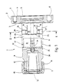
- FIG. 1 shows, as an example of the new setting device, a collet holder device 1 which is to be placed and fastened on a holder flange of a machine spindle (not shown further).
- the collet holder has at one end a disk-shaped mounting flange 2 with two mutually parallel end faces 3 and 4.
- In the face-ground end face 4 there is a cylindrical center hole 5 coaxial with the longitudinal axis of the fastening flange 2, which allows the fastening flange to be adjusted to a very small tolerance Attach tool holder.
- To the side of the centering hole 5 there is an index hole 6 and four threaded holes 7, by means of which the fastening flange can be screwed onto the tool holder.
- a prismatic, in the special case cylindrical shaft 8 is connected in one piece to the end face 3, the longitudinal axis of which is essentially aligned with the longitudinal axis of the fastening flange.
- the shaft 8 is provided with a cylindrical external thread 14 onto which a union nut 15 is to be screwed in order to clamp the collet 13 in the conical bore 12.
- the cylindrical shaft 8 contains two U-shaped slots 16 and 17 which are U-shaped in cross section and, at right angles to the longitudinal axis of the cylindrical shaft 8, these two U-shaped slots 16 and 17, which , are arranged crosswise with respect to the longitudinal axis, have the same shape and are offset in height in the longitudinal direction of the cylindrical shaft 8, so that a disc-shaped intermediate piece 18 is formed between them, which is free of parts of the two slots 16 and 17.
- the U-shaped slot 16 which extends completely through the cylindrical shaft 8 from one side to the diametrically opposite side, is delimited by two mutually parallel legs 19 and 21 and a flat base section 22 running at right angles to the two legs 19 and 21. Because of the position of the U-shaped slot 16, the two legs 19 and 21 run on diametrical sides of the longitudinal axis of the shaft 8 with a radius that is approximately half the radius of the shaft 8. They extend parallel to the longitudinal axis of the shaft 8, while the straight base section 22 intersects the longitudinal axis at right angles.
- the width of the slot is the same everywhere in the region of its legs 19 and 21 and of the base section 22 and is between 1 and a maximum of 2 mm, ie it is small compared to the diameter of the cylindrical shaft 8.
- the distance between the two straight legs 19 and 21 is approximately equal to their length, measured parallel to the longitudinal axis of the shaft 8.
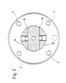
- Fig. 2 shows clearly how the two legs 19 and 21 of the U-shaped slot 16 pass completely through the shaft 8 from one to the other side, such that the intermediate piece 18 with the mounting flange 2 over two circular segment-shaped links 23 and 24 is integrally connected. Due to the material used for the collet holder, the two links 23 and 24 are elastically deflectable, and because of the non-rotationally symmetrical cross-sectional area they have less flexibility in the direction perpendicular to the legs 19 and 21, while they have a great strength in the direction show in parallel. They are therefore spring elements that have the characteristics of band springs.
- the intermediate piece 18 is consequently connected to the fastening flange 2 by means of two spring elements with band spring characteristics that run parallel to one another, that is to say the disk-shaped intermediate piece 18 and the fastening flange 2 can be moved against one another in a plane which is parallel to the drawing plane of FIG. 1 by a relatively small force runs while they are immobile in the direction perpendicular to it. Because of the parallel course of the two spring elements 23 and 24, there is an axially parallel offset between the disk-shaped intermediate piece 18 and the fastening flange 2.
- the slot 17 has the same dimensions as the slot 16, except that it is located between the disk-shaped intermediate piece 18 and the end 9 containing the conical bore 12 and is arranged in a crossed manner with respect to the slot 16 with respect to the longitudinal axis of the cylindrical shaft 8, as shown in FIG. 1 clearly shows.
- an abutment member 33 extends between the two spring members 31 and 32, on which support two screws 34 which are located at the same height and which lie directly in the vicinity of the straight base section 35 on the diameter of the shaft 8 and, as before, cut the spring members 31 and 32 at right angles in the same way as for the spring members 23 and 24. Otherwise, that applies in connection with the U-shaped slot 16, what has been said in an analogous manner also for the U-shaped slot 17 with its straight legs and the straight base section 35 extending at right angles to the longitudinal axis.
- This arrangement which is very robust, can be produced in the simplest manner by the two U-shaped slots 16 and 17 being eroded into the prefabricated collet holder device with the aid of copper electrodes which are shaped accordingly.
- the new adjusting device is used in the following manner: First, the respective tool is inserted into the collet 13, an adjusting screw 36 located at the base of the conical bore 12 determining the insertion depth of the tool into the collet holding device 1. After the union nut 15 has been tightened, the tool is clamped in the collet receiving device, an offset between the tool axis and the cylindrical centering bore 5 resulting due to the tolerances between the position of the conical bore 12 and the cylindrical centering bore 5. In order to compensate for this misalignment, ie to set the tool axis to zero, the collet device with the picked tool is mounted on the machine spindle or a tool presetting device. Then all four locking screws 27, 28, 34 are loosened and the tool axis can now be set to zero by tightening the corresponding locking screw on the two U-shaped slots 16 and 17.
- the corresponding locking screw 27, 28, 34 is supported on the corresponding abutment 29 or 33 in order to press the disk-shaped intermediate piece 18 or the cylindrical end 9 to the side of the longitudinal axis on which the locking screw 27, 28, 34 lies.
Landscapes
- Engineering & Computer Science (AREA)
- Mechanical Engineering (AREA)
- Jigs For Machine Tools (AREA)
- Clamps And Clips (AREA)
- Machine Tool Units (AREA)
- Pressure Welding/Diffusion-Bonding (AREA)
- Push-Button Switches (AREA)
- Turning (AREA)
- Gripping On Spindles (AREA)
- Workshop Equipment, Work Benches, Supports, Or Storage Means (AREA)
Abstract
Description
- Die Erfindung betrifft eine Einstellvorrichtung, insbesondere für rundlaufende Werkzeuge, mit den Merkmalen des Oberbegriffes des Anspruches 1.
- Aus der Praxis sind beispielsweise zur Aufnahme von Reibahlen sogenannte Pendelhalter bekannt, die es gestatten, einen Achsversatz zwischen der Maschinenspindel, in der die Reibahle gehaltert ist und der Bohrung in einem Werkstück auszugleichen. Zu diesem Zweck enthalten die Pendelhalter zwei um 90o gegeneinander versetzte Schiebeführungen, damit ohne Änderung des Winkels zwischen der Achse der Reibahle und der Maschinenspindel der Seitenausgleich erfolgen kann. Derartige Pendelhalter sind jedoch nicht dazu vorgesehen, den Achsversatz zwischen der Werkzeugachse und der Spindelachse fest einzustellen bzw. falls vorhanden, auf null zu kompensieren.
- Ausgehend hiervon ist es Aufgabe der Erfindung, eine Einstellvorrichtung, insbesondere für rundlaufende Werkzeuge zu schaffen, mit der es möglich ist, einen definierten Achsversatz zwischen zwei miteinander gekuppelten Elementen einzustellen und diesen Achsversatz über einen langen Zeitraum beizubehalten.
- Diese Aufgabe wird erfindungsgemäß durch die Einstellvorrichtung mit den Merkmalen des Anspruches 1 gelöst.
- Weil zwei Federglieder vorgesehen sind, um die beiden Elemente miteinander zu kuppeln, sind keine kompliziert zu fertigenden Führungen erforderlich, um die notwendige Beweglichkeit der Elemente gegeneinander zu erzeugen. Vielmehr genügt eine Verwindung der Federglieder, um die gewünschte Lage der Elemente zueinander zu erhalten. Gleichzeitig ist die Verbindung zwischen den Elementen mittels der Federglieder spielfrei, womit sich einfache Herstellungsverhältnisse ergeben.
- Je nach Ausbildung der beiden parallel und mit Abstand voneinander angeordneten Federglieder ist eine Verstellung nur in einer oder auch in zwei Ebenen möglich. Wenn die Federglieder derart gestaltet sind, daß sie nur in einer Ebene elastisch auslenkbar sind, die eine Längsachse eines der Elemente umfaßt, während sie in der dazu rechtwinkligen Ebene, die ebenfalls die Längsachse enthält, weitgehend starr sind, ergibt sich eine Parallelogrammführung,mit deren Hilfe die beiden Elemente ausschließlich in einer Ebene gegeneinander versetzbar sind. Falls dies nicht ausreicht, wenn Lagetoleranzen in beliebigen Richtungen auftreten können, besteht die einfache Möglichkeit, einen weiteren Satz von gleich ausgebildeten Federgliedern zu verwenden, die jedoch, bezogen auf die Längsachse der Elemente, um 90o gegenüber den ersten gedreht angeordnet sind.
- Zufolge einer parallelen Anordnung der Federglieder innerhalb jedes Paares, die ähnlich Bandfedern gestaltet sind, ergibt sich zwangsläufig ein exakt paralleler Versatz der Elemente gegeneinander.
- Wenn die Widerlagermittel jeweils zwischen den Federgliedern eines Paares angeordnet sind, ergeben sich besonders einfache platzsparende Verhältnisse.
- Die Feststellmittel zur Fixierung der Federglieder gegenüber den Widerlagermitteln sind im einfachsten Falle Feststellschrauben, die bevorzugt in Gewindelöchern sitzen, die sich in den Federgliedern befinden.
- Die erfindungsgemäße Einstellvorrichtung läßt sich einstückig besonders einfach dadurch herstellen, daß in einem Zwischenstück, das bevorzugt die beiden Elemente einstückig miteinander verbindet, ein oder zwei U-förmige Schlitze eingearbeitet sind, die bezüglich der Längsachse diametral liegende Seitenflächen des Zwischenstücks durchsetzen und jeweils aus zwei parallel zu der Längsachse verlaufenden Schenkeln sowie einem die Längsachse rechtwinklig schneidenden Basisstück bestehen. Solche Schlitze lassen sich durch eine entsprechend geformte Elektrode in einfachster Weise in das Zwischenstück erodieren, wobei nur geringe Anforderungen an die Fertigungsgenauigkeit gestellt werden. Das längliche Zwischenstück kann dabei sowohl einen rechteckigen als auch einen Kreisquerschnitt aufweisen.
- In der Zeichnung ist ein Ausführungsbeispiel des Gegenstandes der Erfindung dargestellt. Es zeigen:
- Fig. 1 die Einstellvorrichtung gemäß der Erfindung in einer Seitenansicht und teilweise geschnitten und
- Fig 2 die Einstellvorrichtung nach Fig. 1, geschnitten längs der Linie II-II aus Fig. 1 in einer Draufsicht.
- In Fig. 1 ist als Beispiel für die neue Einstellvorrichtung eine Spannzangenaufnahmevorrichtung 1 veranschaulicht, die auf einem Aufnahmeflansch einer nicht weiter gezeigten Maschinenspindel aufzusetzen und zu befestigen ist. Die Spannzangenaufnahmevorrichtung trägt an einem Ende einen scheibenförmigen Befestigungsflansch 2 mit zwei zueinander parallelen Stirnseiten 3 und 4. In der plangeschliffenen Stirnseite 4 ist koaxial zu der Längsachse des Befestigungsflansches 2 eine zylindrische Zentrierbohrung 5 vorhanden, die es gestattet, den Befestigungsflansch mit sehr kleiner Toleranz auf eine Werkzeugaufnahme aufzusetzen. Seitlich neben der Zentrierbohrung 5 befindet sich eine Indexbohrung 6 sowie vier Gewindebohrungen 7, mittels derer der Befestigungsflansch an der Werkzeugaufnahme festzuschrauben ist.
- Mit der Stirnfläche 3 ist ein prismatischer, im speziellen Falle zylindrischer Schaft 8 einstückig verbunden, dessen Längsachse im wesentlichen mit der Längsachse des Befestigungsflansches fluchtet. An seinem dem Befestigungsflansch abgelegenen Ende 9 enthält er in seiner zu der Stirnfläche 4 parallelen Stirnfläche 11 eine konische, sich in Richtung auf den Befestigungsflansch 2 verjüngende Bohrung 12 für eine darin sitzende, in Längsrichtung geschlitzte Spannzange 13, die als Druckspannzange ausgebildet ist und die übliche Gestalt hat. In der Nähe der Stirnseite 11 ist der Schaft 8 mit einem zylindrischen Außengewinde 14 versehen, auf das eine Überwurfmutter 15 aufzuschrauben ist, um die Spannzange 13 in der konischen Bohrung 12 festzuklemmen.
- Das zylindrische Ende 9 und der Befestigungsflansch 2 bilden zwei achsparallel gegeneinander zu verstellende Elemente der neuen Einstellvorrichtung. Um diese Verstellbarkeit zu schaffen, enthält der zylindrische Schaft 8 zwei im Querschnitt U-förmige und, bezogen auf die Längsachse des zylindrischen Schaftes 8, rechtwinklig angeordnete, U-förmige Schlitze 16 und 17. Diese beiden U-förmigen Schlitze 16 und 17, die, bezogen auf die Längsachse, gekreuzt angeordnet sind, haben dieselbe Gestalt und sind in Längsrichtung des zylindrischen Schaftes 8 höhenversetzt, so daß zwischen ihnen ein scheibenförmiges Zwischenstück 18 entsteht, das frei von Teilen der beiden Schlitze 16 und 17 ist.
- Der U-förmige Schlitz 16, der den zylindrischen Schaft 8 vollständig von einer bis zu der diametral gegenüberliegenden Seite hin durchsetzt, wird von zwei zueinander parallelen Schenkeln 19 und 21 sowie einem zu den beiden Schenkeln 19 und 21 rechtwinklig verlaufenden ebenen Basisabschnitt 22 begrenzt. Wegen der Lage des U-förmigen Schlitzes 16 verlaufen die beiden Schenkel 19 und 21 an diametralen Seiten der Längsachse des Schaftes 8 mit einem Radius, der etwa halb so groß ist wie der Radius des Schaftes 8. Sie erstrecken sich parallel zu der Längsachse des Schaftes 8, während der gerade verlaufende Basisabschnitt 22 die Längsachse rechtwinklig schneidet. Die Weite des Schlitzes ist im Bereich seiner Schenkel 19 und 21 sowie des Basisabschnittes 22 überall gleich und beträgt zwischen 1 und maximal 2 mm, d.h. sie ist klein gegenüber dem Durchmesser des zylindrischen Schaftes 8.
- Den Abstand, den die beiden geraden Schenkel 19 und 21 voneinander haben, ist etwa gleich ihrer Länge, gemessen parallel zu der Längsachse des Schaftes 8.
- Fig. 2 läßt deutlich erkennen, wie die beiden Schenkel 19 und 21 des U-förmigen Schlitzes 16 vollständig durch den Schaft 8 von einer bis zu der anderen Seite durchlaufen, derart, daß das Zwischenstück 18 mit dem Befestigungsflansch 2 über zwei im Querschnitt kreissegmentförmige Glieder 23 und 24 einstückig verbunden ist. Infolge des Materials, das für die Spannzangenaufnahmevorrichtung verwendet ist, sind die beiden Glieder 23 und 24 elastisch auslenkbar, und zwar haben Sie wegen der nicht rotationssymmetrischen Querschnittsfläche eine geringere Nachgiebigkeit in Richtung senkrecht zu den Schenkeln 19 und 21, während sie eine große Festigkeit in Richtung parallel dazu zeigen. Sie sind deswegen Federglieder, die die Charakteristik von Bandfedern aufweisen. Das Zwischenstück 18 ist folglich mit dem Befestigungsflansch 2 über zwei parallel zueinander verlaufende Federglieder mit Bandfedercharakterstik verbunden, d.h. das scheibenförmige Zwischenstück 18 und der Befestigungsflansch 2 können durch eine verhältnismäßig geringe Kraft gegeneinander in einer Ebene bewegt werden, die parallel zu der Zeichenebene von Fig. 1 verläuft, während sie in Richtung senkrecht dazu unbeweglich sind. Wegen des parallelen Verlaufs der beiden Federglieder 23 und 24 ergibt sich ein achsparalleler Versatz zwischen dem scheibenförmigen Zwischenstück 18 und dem Befestigungsflansch 2.
- Um eine definierte Lage zwischen dem scheibenförmigen Zwischenstück 18 und dem Befestigungsflansch 2 auch in Richtung parallel zu der Zeichenebene zu erhalten, sind in der Nähe des Basisabschnittes 22 in den beiden Federgliedern 23 und 24 zwei miteinander fluchtende Gewindebohrungen 25 und 26 enthalten, die bis zu dem Schlitz 16 reichen. In diesen miteinander fluchtenden Gewindebohrungen 25 und 26 sitzen zwei Stiftschrauben 27 und 28, die sich an einem von dem Schlitz 16 umgrenzten Widerlager 29 abstützen. Das Widerlager 29 ist ein mit dem Befestigungsflansch einstückig verbundener, im wesentlichen quaderförmiger Körper, der beim Einarbeiten des U-förmigen Schlitzes 16 innen stehen bleibt. Er weist eine sehr große Festigkeit in allen Richtungen auf, weshalb er tatsächlich die Funktion des Widerlagers für die Einstellschrauben 27 und 28 bringen kann.
- Der Schlitz 17 hat dieselben Abmessungen wie der Schlitz 16, nur befindet er sich zwischen dem scheibenförmigen Zwischenstück 18 und dem die konische Bohrung 12 enthaltenden Ende 9 und ist zu dem Schlitz 16 bezüglich der Längsachse des zylindrischen Schaftes 8 gekreuzt angeordnet, wie dies Fig. 1 deutlich erkennen läßt. Hierdurch entstehen zwei gegenüber den Federgliedern 23 und 24 gekreuzt angeordnete Federglieder 31 bzw. 32 an der in Fig. 1 nicht sichtbar gegenüberliegenden Seite der Spannzangenaufnahmevorrichtung 1. Zwischen den beiden Federgliedern 31 und 32 erstreckt sich, wie vorher, ein Widerlagerglied 33, an dem sich zwei auf gleicher Höhe sitzende Schrauben 34 abstützen, die unmittelbar in der Nähe des geraden Basisabschnittes 35 auf dem Durchmesser des Schaftes 8 liegen und wie vorher in der gleichen Weise wie bei den Federgliedern 23 und 24 die Federglieder 31 und 32 rechtwinklig schneiden. Im übrigen gilt das im Zusammenhang mit dem U-förmigen Schlitz 16 Gesagte in sinngemäßer Weise auch für den U-förmigen Schlitz 17 mit seinen gerade verlaufenden Schenkeln und dem rechtwinklig zu der Längsachse sich erstreckenden geraden Basisabschnitt 35.
- Diese Anordnung, die sehr robust ist, läßt sich in einfachster Weise dadurch herstellen, daß in die vorgefertigte Spannzangenaufnahmevorrichtung mit Hilfe von Kupferelektroden,die entsprechend geformt sind, die beiden U-förmigen Schlitze 16 und 17 einerodiert werden.
- Die Verwendung der neuen Einstellvorrichtung geschieht in folgender Weise: Zunächst wird in die Spannzange 13 das jeweilige Werkzeug eingesetzt, wobei eine an dem Grund der kegeligen Bohrung 12 befindliche Einstellschraube 36 die Einstecktiefe des Werkzeugs in die Spannzangenaufnahmevorrichtung 1 festlegt. Nach dem Anziehen der Überwurfmutter 15 ist das Werkzeug in der Spannzangenaufnahmevorrichtung festgeklemmt, wobei sich wegen der Toleranzen zwischen der Lage der kegeligen Bohrung 12 und der zylindrischen Zentrierbohrung 5 ein Versatz zwischen der Werkzeugachse und dr zylindrischen Zentrierbohrung 5 ergibt. Um diesen Versatz zu kompensieren, d.h. die Achse des Werkzeugs auf null zu stellen, wird die Spannzangenvorrichtung mit dem aufgenommenen Werkzeug auf der Maschinenspindel oder einem Werkzeug-Voreinstellgerät montiert. Danach werden alle vier Feststellschrauben 27, 28, 34 gelockert und nun kann durch Festziehen der entsprechenden Feststellschraube an den beiden U-förmigen Schlitzen 16 und 17 die Werkzeugachse auf null gestellt werden.
- Dabei stützt sich die entsprechende Feststellschraube 27, 28, 34 auf dem entsprechenden Widerlager 29 bzw. 33 ab, um das scheibenförmige Zwischenstück 18 bzw. das zylindrische Ende 9 zu der Seite der Längsachse zu drücken, auf der die jeweils betätigte Feststellschraube 27, 28, 34 liegt. Nachdem durch entsprechendes Betätigen jeweils einer der Feststellschrauben 27, 28, 34 aus dem Satz die Achse des eingesetzten Werkzeugs zu der Achse des Befestigungsflansches 2 auf null justiert ist, wird die entsprechende gegenüberliegende Feststellschraube 27, 28, 34 jedes Satzes gegen das Widerlager 29 und 33 festgeschraubt, so daß sich eine Konterung ergibt. Damit ist das Werkzeug in allen Richtungen justiert und kann auch durch seitlich auftretende Kräfte,von der Eigenelastizität abgesehen, nicht seitlich verdrückt werden.
Claims (15)
Priority Applications (1)
| Application Number | Priority Date | Filing Date | Title |
|---|---|---|---|
| AT89110953T ATE79066T1 (de) | 1988-07-19 | 1989-06-16 | Einstellvorrichtung, insbesondere fuer werkzeuge. |
Applications Claiming Priority (2)
| Application Number | Priority Date | Filing Date | Title |
|---|---|---|---|
| DE3824462A DE3824462A1 (de) | 1988-07-19 | 1988-07-19 | Einstellvorrichtung, insbesondere fuer werkzeuge |
| DE3824462 | 1988-07-19 |
Publications (2)
| Publication Number | Publication Date |
|---|---|
| EP0353436A1 true EP0353436A1 (de) | 1990-02-07 |
| EP0353436B1 EP0353436B1 (de) | 1992-08-05 |
Family
ID=6359022
Family Applications (1)
| Application Number | Title | Priority Date | Filing Date |
|---|---|---|---|
| EP89110953A Expired - Lifetime EP0353436B1 (de) | 1988-07-19 | 1989-06-16 | Einstellvorrichtung, insbesondere für Werkzeuge |
Country Status (6)
| Country | Link |
|---|---|
| US (1) | US4930957A (de) |
| EP (1) | EP0353436B1 (de) |
| AT (1) | ATE79066T1 (de) |
| DD (1) | DD285562A5 (de) |
| DE (2) | DE3824462A1 (de) |
| ES (1) | ES2037911T3 (de) |
Cited By (2)
| Publication number | Priority date | Publication date | Assignee | Title |
|---|---|---|---|---|
| EP0713739A3 (de) * | 1994-11-23 | 1996-07-31 | Stellram Sa | Bearbeitungswerkzeug mit Schneideinsätze |
| EP1839786A1 (de) * | 2006-03-31 | 2007-10-03 | Eugen Fahrion GmbH & Co. | Spannzangenfutter |
Families Citing this family (15)
| Publication number | Priority date | Publication date | Assignee | Title |
|---|---|---|---|---|
| DE9006613U1 (de) * | 1990-06-12 | 1990-08-23 | Hörl, Bernhard, 7121 Erligheim | Spanneinrichtung |
| DE4023580C1 (de) * | 1990-07-25 | 1991-08-14 | Gebr. Heller Maschinenfabrik Gmbh, 7440 Nuertingen, De | |
| CH681964A5 (de) * | 1990-08-21 | 1993-06-30 | Planetron Ag | |
| EP0483807A3 (en) * | 1990-11-02 | 1992-09-02 | Kiyoshi Miyashita | Boring bar |
| DE9109300U1 (de) * | 1991-07-27 | 1992-11-26 | Eugen Fahrion GmbH & Co Präzisionswerkzeugfabriken, 7300 Esslingen | Spannzangenfutter |
| DE4209485A1 (de) * | 1991-07-27 | 1993-01-28 | Fahrion Eugen Gmbh | Spannzangenfutter |
| DE9205838U1 (de) * | 1992-04-30 | 1992-11-05 | Eugen Fahrion GmbH & Co Präzisionswerkzeugfabriken, 7300 Esslingen | Spannzangenfutter |
| DE4204644C2 (de) * | 1992-02-15 | 1995-04-27 | Heidelberger Druckmasch Ag | Vorrichtung zur Einstellung eines Werkzeuganschlags in einer Werkzeugspindel |
| US5286042A (en) * | 1993-03-24 | 1994-02-15 | Hydra-Lock Corporation | Tool holder with centering adjustment |
| DE4447558C5 (de) * | 1994-08-25 | 2004-04-29 | Gühring, Jörg, Dr. | Rundlaufendes Werkzeug |
| JP4071576B2 (ja) * | 2002-08-26 | 2008-04-02 | 株式会社森精機製作所 | 工作機械 |
| DE10258448A1 (de) | 2002-12-13 | 2004-06-24 | Franz Haimer Maschinenbau Kg | Zentriervorrichtung, insbesondere für eine Tastmessvorrichtung |
| US20060115337A1 (en) * | 2004-12-01 | 2006-06-01 | Fusao Higashi | Runout eliminating collet chuck |
| DE102007020633B4 (de) * | 2007-04-30 | 2009-04-16 | Gottfried Wilhelm Leibniz Universität Hannover | Positioniervorrichtung |
| DE102014106328B4 (de) | 2014-05-07 | 2024-06-06 | Hermann LeGuin | Verfahren zum Herstellen eines Halters für ein Werkzeug und/oder ein Werkstück sowie entsprechender Halter |
Citations (7)
| Publication number | Priority date | Publication date | Assignee | Title |
|---|---|---|---|---|
| DE2228553A1 (de) * | 1972-06-12 | 1974-01-10 | Samson Apparatebau Ag | Werkzeugtraeger |
| DE2835712A1 (de) * | 1978-08-16 | 1980-02-28 | Bosch Gmbh Robert | Fuehler zum ausrichten von teilen |
| EP0058646A2 (de) * | 1981-02-12 | 1982-08-25 | WORKMEN MACHINE TOOLS S.c.r.l. | Werkzeughalter mit Mitteln für die radiale Einstellung des Werkzeuges |
| US4351207A (en) * | 1980-10-03 | 1982-09-28 | Werth Engineering, Inc. | Micrometrically adjusted tool arm assembly |
| FR2534682A1 (fr) * | 1982-10-18 | 1984-04-20 | Finike Italiana Marposs | Tete de palpeur pour la verification de dimensions lineaires |
| DE3446275C1 (de) * | 1984-12-19 | 1986-07-24 | Samson Ag, 6000 Frankfurt | Umlaufender Bohrkopf mit einer zwischen einem Anschlussschaft und einem Werkzeugtraeger angeordneten Zustelleinrichtung |
| EP0251405A1 (de) * | 1986-06-25 | 1988-01-07 | Plansee Tizit Gesellschaft M.B.H. | Stellelement für Schneidwerkzeuge |
Family Cites Families (5)
| Publication number | Priority date | Publication date | Assignee | Title |
|---|---|---|---|---|
| US2960013A (en) * | 1956-06-19 | 1960-11-15 | Portage Double Quick Inc | Offsetting attachment for rotating spindle |
| WO1980001364A1 (en) * | 1978-12-26 | 1980-07-10 | Caterpillar Tractor Co | Deflectable holding assembly |
| US4281482A (en) * | 1979-10-04 | 1981-08-04 | Sunnen Products Company | Spindle nose for machine tools |
| EP0235327B1 (de) * | 1986-03-03 | 1990-08-22 | Dihart AG | Werkzeughalter |
| DE3636581A1 (de) * | 1986-10-28 | 1988-05-19 | Glimpel Emuge Werk | Spannvorrichtung fuer werkstuecke oder werkzeuge mit hoher rundlaufgenauigkeit |
-
1988
- 1988-07-19 DE DE3824462A patent/DE3824462A1/de active Granted
-
1989
- 1989-06-16 DE DE8989110953T patent/DE58901977D1/de not_active Expired - Lifetime
- 1989-06-16 EP EP89110953A patent/EP0353436B1/de not_active Expired - Lifetime
- 1989-06-16 ES ES198989110953T patent/ES2037911T3/es not_active Expired - Lifetime
- 1989-06-16 AT AT89110953T patent/ATE79066T1/de not_active IP Right Cessation
- 1989-07-17 DD DD89330897A patent/DD285562A5/de not_active IP Right Cessation
- 1989-08-03 US US07/388,997 patent/US4930957A/en not_active Expired - Fee Related
Patent Citations (7)
| Publication number | Priority date | Publication date | Assignee | Title |
|---|---|---|---|---|
| DE2228553A1 (de) * | 1972-06-12 | 1974-01-10 | Samson Apparatebau Ag | Werkzeugtraeger |
| DE2835712A1 (de) * | 1978-08-16 | 1980-02-28 | Bosch Gmbh Robert | Fuehler zum ausrichten von teilen |
| US4351207A (en) * | 1980-10-03 | 1982-09-28 | Werth Engineering, Inc. | Micrometrically adjusted tool arm assembly |
| EP0058646A2 (de) * | 1981-02-12 | 1982-08-25 | WORKMEN MACHINE TOOLS S.c.r.l. | Werkzeughalter mit Mitteln für die radiale Einstellung des Werkzeuges |
| FR2534682A1 (fr) * | 1982-10-18 | 1984-04-20 | Finike Italiana Marposs | Tete de palpeur pour la verification de dimensions lineaires |
| DE3446275C1 (de) * | 1984-12-19 | 1986-07-24 | Samson Ag, 6000 Frankfurt | Umlaufender Bohrkopf mit einer zwischen einem Anschlussschaft und einem Werkzeugtraeger angeordneten Zustelleinrichtung |
| EP0251405A1 (de) * | 1986-06-25 | 1988-01-07 | Plansee Tizit Gesellschaft M.B.H. | Stellelement für Schneidwerkzeuge |
Cited By (2)
| Publication number | Priority date | Publication date | Assignee | Title |
|---|---|---|---|---|
| EP0713739A3 (de) * | 1994-11-23 | 1996-07-31 | Stellram Sa | Bearbeitungswerkzeug mit Schneideinsätze |
| EP1839786A1 (de) * | 2006-03-31 | 2007-10-03 | Eugen Fahrion GmbH & Co. | Spannzangenfutter |
Also Published As
| Publication number | Publication date |
|---|---|
| DE3824462C2 (de) | 1990-08-23 |
| DE58901977D1 (de) | 1992-09-10 |
| DE3824462A1 (de) | 1990-01-25 |
| DD285562A5 (de) | 1990-12-19 |
| ES2037911T3 (es) | 1993-07-01 |
| US4930957A (en) | 1990-06-05 |
| EP0353436B1 (de) | 1992-08-05 |
| ATE79066T1 (de) | 1992-08-15 |
Similar Documents
| Publication | Publication Date | Title |
|---|---|---|
| EP0353436B1 (de) | Einstellvorrichtung, insbesondere für Werkzeuge | |
| DE19940330C2 (de) | Werkzeugspanneinrichtung | |
| EP0126432B1 (de) | Fräswerkzeug | |
| EP0141451B1 (de) | Werkzeugaufnahmevorrichtung und Werkzeugträger | |
| EP0111092A1 (de) | Kupplungsvorrichtung | |
| EP0674561A1 (de) | Vollbohrer | |
| WO2003051563A1 (de) | Werkzeughalter für schneidkörper | |
| EP0962280B1 (de) | Ausrichteinrichtung | |
| EP0285704B1 (de) | Mehrteiliges Spannsystem, insbesondere für rundlaufende Werkzeuge | |
| DE3029133C2 (de) | Werkzeughalter | |
| DE8407867U1 (de) | Bohrstangeneinsatz | |
| EP1390792A2 (de) | Positioniereinrichtung | |
| DE3439040A1 (de) | Vorrichtung zur verbindung eines werkzeughalters mit einer werkzeughalteraufnahme | |
| DE3432942C2 (de) | ||
| EP1514623B1 (de) | Werkzeugmaschine und hierzu vorgesehener Werkzeugträger | |
| DE8335033U1 (de) | Kupplungsvorrichtung | |
| DE20009102U1 (de) | Ausrichteinrichtung | |
| DE19517365B4 (de) | Werkzeughalter | |
| EP1314516B1 (de) | Halteelement | |
| DE2726734C2 (de) | Einstechwerkzeug und Verfahren zum Fertigbearbeiten eines solchen Einstechwerkzeugs | |
| EP1559490B1 (de) | Werkzeughalter | |
| DE10137055A1 (de) | Kupplungsvorrichtung für das Verbinden einer Spindel mit einem Werkzeughalter | |
| DE3026513A1 (de) | Aufbohrwerkzeug, insbes. plansenker | |
| DE19907100B4 (de) | Vorrichtung zum Positionieren eines Werkzeuges oder Werkstückes an einer Werkzeugmaschine | |
| CH624329A5 (en) | Method of clamping a workpiece in order to machine or inspect it, and clamping body for carrying out the method |
Legal Events
| Date | Code | Title | Description |
|---|---|---|---|
| PUAI | Public reference made under article 153(3) epc to a published international application that has entered the european phase |
Free format text: ORIGINAL CODE: 0009012 |
|
| AK | Designated contracting states |
Kind code of ref document: A1 Designated state(s): AT BE CH DE ES FR GB GR IT LI LU NL SE |
|
| 17P | Request for examination filed |
Effective date: 19900203 |
|
| 17Q | First examination report despatched |
Effective date: 19910228 |
|
| GRAA | (expected) grant |
Free format text: ORIGINAL CODE: 0009210 |
|
| AK | Designated contracting states |
Kind code of ref document: B1 Designated state(s): AT BE CH DE ES FR GB GR IT LI LU NL SE |
|
| PG25 | Lapsed in a contracting state [announced via postgrant information from national office to epo] |
Ref country code: GR Free format text: LAPSE BECAUSE OF FAILURE TO SUBMIT A TRANSLATION OF THE DESCRIPTION OR TO PAY THE FEE WITHIN THE PRESCRIBED TIME-LIMIT Effective date: 19920805 |
|
| REF | Corresponds to: |
Ref document number: 79066 Country of ref document: AT Date of ref document: 19920815 Kind code of ref document: T |
|
| ITF | It: translation for a ep patent filed | ||
| GBT | Gb: translation of ep patent filed (gb section 77(6)(a)/1977) | ||
| REF | Corresponds to: |
Ref document number: 58901977 Country of ref document: DE Date of ref document: 19920910 |
|
| ET | Fr: translation filed | ||
| PLBE | No opposition filed within time limit |
Free format text: ORIGINAL CODE: 0009261 |
|
| STAA | Information on the status of an ep patent application or granted ep patent |
Free format text: STATUS: NO OPPOSITION FILED WITHIN TIME LIMIT |
|
| REG | Reference to a national code |
Ref country code: ES Ref legal event code: FG2A Ref document number: 2037911 Country of ref document: ES Kind code of ref document: T3 |
|
| 26N | No opposition filed | ||
| EPTA | Lu: last paid annual fee | ||
| EAL | Se: european patent in force in sweden |
Ref document number: 89110953.0 |
|
| PGFP | Annual fee paid to national office [announced via postgrant information from national office to epo] |
Ref country code: LU Payment date: 19960601 Year of fee payment: 8 |
|
| PGFP | Annual fee paid to national office [announced via postgrant information from national office to epo] |
Ref country code: GB Payment date: 19960607 Year of fee payment: 8 |
|
| PGFP | Annual fee paid to national office [announced via postgrant information from national office to epo] |
Ref country code: AT Payment date: 19960611 Year of fee payment: 8 |
|
| PGFP | Annual fee paid to national office [announced via postgrant information from national office to epo] |
Ref country code: FR Payment date: 19960619 Year of fee payment: 8 |
|
| PGFP | Annual fee paid to national office [announced via postgrant information from national office to epo] |
Ref country code: CH Payment date: 19960626 Year of fee payment: 8 |
|
| PGFP | Annual fee paid to national office [announced via postgrant information from national office to epo] |
Ref country code: SE Payment date: 19960628 Year of fee payment: 8 |
|
| PGFP | Annual fee paid to national office [announced via postgrant information from national office to epo] |
Ref country code: NL Payment date: 19960630 Year of fee payment: 8 |
|
| PGFP | Annual fee paid to national office [announced via postgrant information from national office to epo] |
Ref country code: BE Payment date: 19960711 Year of fee payment: 8 |
|
| PGFP | Annual fee paid to national office [announced via postgrant information from national office to epo] |
Ref country code: ES Payment date: 19960930 Year of fee payment: 8 |
|
| PG25 | Lapsed in a contracting state [announced via postgrant information from national office to epo] |
Ref country code: LU Free format text: LAPSE BECAUSE OF NON-PAYMENT OF DUE FEES Effective date: 19970616 Ref country code: GB Free format text: LAPSE BECAUSE OF NON-PAYMENT OF DUE FEES Effective date: 19970616 Ref country code: AT Effective date: 19970616 |
|
| PG25 | Lapsed in a contracting state [announced via postgrant information from national office to epo] |
Ref country code: SE Effective date: 19970617 Ref country code: ES Free format text: LAPSE BECAUSE OF EXPIRATION OF PROTECTION Effective date: 19970617 |
|
| PG25 | Lapsed in a contracting state [announced via postgrant information from national office to epo] |
Ref country code: LI Free format text: LAPSE BECAUSE OF NON-PAYMENT OF DUE FEES Effective date: 19970630 Ref country code: CH Free format text: LAPSE BECAUSE OF NON-PAYMENT OF DUE FEES Effective date: 19970630 Ref country code: BE Effective date: 19970630 |
|
| BERE | Be: lapsed |
Owner name: EBERHARD BAUER G.M.B.H. & CO. Effective date: 19970630 |
|
| PG25 | Lapsed in a contracting state [announced via postgrant information from national office to epo] |
Ref country code: NL Effective date: 19980101 |
|
| GBPC | Gb: european patent ceased through non-payment of renewal fee |
Effective date: 19970616 |
|
| REG | Reference to a national code |
Ref country code: CH Ref legal event code: PL |
|
| PG25 | Lapsed in a contracting state [announced via postgrant information from national office to epo] |
Ref country code: FR Free format text: LAPSE BECAUSE OF NON-PAYMENT OF DUE FEES Effective date: 19980227 |
|
| EUG | Se: european patent has lapsed |
Ref document number: 89110953.0 |
|
| NLV4 | Nl: lapsed or anulled due to non-payment of the annual fee |
Effective date: 19980101 |
|
| REG | Reference to a national code |
Ref country code: FR Ref legal event code: ST |
|
| REG | Reference to a national code |
Ref country code: FR Ref legal event code: ST |
|
| REG | Reference to a national code |
Ref country code: ES Ref legal event code: FD2A Effective date: 20000201 |
|
| PGFP | Annual fee paid to national office [announced via postgrant information from national office to epo] |
Ref country code: DE Payment date: 20040616 Year of fee payment: 16 |
|
| PG25 | Lapsed in a contracting state [announced via postgrant information from national office to epo] |
Ref country code: IT Free format text: LAPSE BECAUSE OF NON-PAYMENT OF DUE FEES;WARNING: LAPSES OF ITALIAN PATENTS WITH EFFECTIVE DATE BEFORE 2007 MAY HAVE OCCURRED AT ANY TIME BEFORE 2007. THE CORRECT EFFECTIVE DATE MAY BE DIFFERENT FROM THE ONE RECORDED. Effective date: 20050616 |
|
| PG25 | Lapsed in a contracting state [announced via postgrant information from national office to epo] |
Ref country code: DE Free format text: LAPSE BECAUSE OF NON-PAYMENT OF DUE FEES Effective date: 20060103 |