EP0349788B1 - Verfahren und Vorrichtung zur Steuerung der Regenerierung, wenigstens eines Partikelfilters, welches in einem Dieselmotor installiert ist - Google Patents
Verfahren und Vorrichtung zur Steuerung der Regenerierung, wenigstens eines Partikelfilters, welches in einem Dieselmotor installiert ist Download PDFInfo
- Publication number
- EP0349788B1 EP0349788B1 EP89110396A EP89110396A EP0349788B1 EP 0349788 B1 EP0349788 B1 EP 0349788B1 EP 89110396 A EP89110396 A EP 89110396A EP 89110396 A EP89110396 A EP 89110396A EP 0349788 B1 EP0349788 B1 EP 0349788B1
- Authority
- EP
- European Patent Office
- Prior art keywords
- clogging
- regeneration
- filter
- intentional
- level
- Prior art date
- Legal status (The legal status is an assumption and is not a legal conclusion. Google has not performed a legal analysis and makes no representation as to the accuracy of the status listed.)
- Expired - Lifetime
Links
Images


Classifications
-
- F—MECHANICAL ENGINEERING; LIGHTING; HEATING; WEAPONS; BLASTING
- F01—MACHINES OR ENGINES IN GENERAL; ENGINE PLANTS IN GENERAL; STEAM ENGINES
- F01N—GAS-FLOW SILENCERS OR EXHAUST APPARATUS FOR MACHINES OR ENGINES IN GENERAL; GAS-FLOW SILENCERS OR EXHAUST APPARATUS FOR INTERNAL-COMBUSTION ENGINES
- F01N3/00—Exhaust or silencing apparatus having means for purifying, rendering innocuous, or otherwise treating exhaust
- F01N3/02—Exhaust or silencing apparatus having means for purifying, rendering innocuous, or otherwise treating exhaust for cooling, or for removing solid constituents of, exhaust
- F01N3/021—Exhaust or silencing apparatus having means for purifying, rendering innocuous, or otherwise treating exhaust for cooling, or for removing solid constituents of, exhaust by means of filters
- F01N3/031—Exhaust or silencing apparatus having means for purifying, rendering innocuous, or otherwise treating exhaust for cooling, or for removing solid constituents of, exhaust by means of filters having means for by-passing filters, e.g. when clogged or during cold engine start
- F01N3/032—Exhaust or silencing apparatus having means for purifying, rendering innocuous, or otherwise treating exhaust for cooling, or for removing solid constituents of, exhaust by means of filters having means for by-passing filters, e.g. when clogged or during cold engine start during filter regeneration only
-
- F—MECHANICAL ENGINEERING; LIGHTING; HEATING; WEAPONS; BLASTING
- F01—MACHINES OR ENGINES IN GENERAL; ENGINE PLANTS IN GENERAL; STEAM ENGINES
- F01N—GAS-FLOW SILENCERS OR EXHAUST APPARATUS FOR MACHINES OR ENGINES IN GENERAL; GAS-FLOW SILENCERS OR EXHAUST APPARATUS FOR INTERNAL-COMBUSTION ENGINES
- F01N3/00—Exhaust or silencing apparatus having means for purifying, rendering innocuous, or otherwise treating exhaust
- F01N3/02—Exhaust or silencing apparatus having means for purifying, rendering innocuous, or otherwise treating exhaust for cooling, or for removing solid constituents of, exhaust
- F01N3/021—Exhaust or silencing apparatus having means for purifying, rendering innocuous, or otherwise treating exhaust for cooling, or for removing solid constituents of, exhaust by means of filters
- F01N3/023—Exhaust or silencing apparatus having means for purifying, rendering innocuous, or otherwise treating exhaust for cooling, or for removing solid constituents of, exhaust by means of filters using means for regenerating the filters, e.g. by burning trapped particles
-
- F—MECHANICAL ENGINEERING; LIGHTING; HEATING; WEAPONS; BLASTING
- F01—MACHINES OR ENGINES IN GENERAL; ENGINE PLANTS IN GENERAL; STEAM ENGINES
- F01N—GAS-FLOW SILENCERS OR EXHAUST APPARATUS FOR MACHINES OR ENGINES IN GENERAL; GAS-FLOW SILENCERS OR EXHAUST APPARATUS FOR INTERNAL-COMBUSTION ENGINES
- F01N9/00—Electrical control of exhaust gas treating apparatus
- F01N9/002—Electrical control of exhaust gas treating apparatus of filter regeneration
-
- F—MECHANICAL ENGINEERING; LIGHTING; HEATING; WEAPONS; BLASTING
- F01—MACHINES OR ENGINES IN GENERAL; ENGINE PLANTS IN GENERAL; STEAM ENGINES
- F01N—GAS-FLOW SILENCERS OR EXHAUST APPARATUS FOR MACHINES OR ENGINES IN GENERAL; GAS-FLOW SILENCERS OR EXHAUST APPARATUS FOR INTERNAL-COMBUSTION ENGINES
- F01N2390/00—Arrangements for controlling or regulating exhaust apparatus
- F01N2390/02—Arrangements for controlling or regulating exhaust apparatus using electric components only
-
- F—MECHANICAL ENGINEERING; LIGHTING; HEATING; WEAPONS; BLASTING
- F02—COMBUSTION ENGINES; HOT-GAS OR COMBUSTION-PRODUCT ENGINE PLANTS
- F02B—INTERNAL-COMBUSTION PISTON ENGINES; COMBUSTION ENGINES IN GENERAL
- F02B3/00—Engines characterised by air compression and subsequent fuel addition
- F02B3/06—Engines characterised by air compression and subsequent fuel addition with compression ignition
-
- Y—GENERAL TAGGING OF NEW TECHNOLOGICAL DEVELOPMENTS; GENERAL TAGGING OF CROSS-SECTIONAL TECHNOLOGIES SPANNING OVER SEVERAL SECTIONS OF THE IPC; TECHNICAL SUBJECTS COVERED BY FORMER USPC CROSS-REFERENCE ART COLLECTIONS [XRACs] AND DIGESTS
- Y02—TECHNOLOGIES OR APPLICATIONS FOR MITIGATION OR ADAPTATION AGAINST CLIMATE CHANGE
- Y02T—CLIMATE CHANGE MITIGATION TECHNOLOGIES RELATED TO TRANSPORTATION
- Y02T10/00—Road transport of goods or passengers
- Y02T10/10—Internal combustion engine [ICE] based vehicles
- Y02T10/40—Engine management systems
Definitions
- This invention relates to a method and apparatus controlling the regeneration of at least one particulate filter installed in a diesel engine of non-supercharged or supercharged type.
- triggering and controlling the combustion of particles which have accumulated within a particulate filter are still the two major problems to be solved in the development of an efficient filtration system for the exhaust gas of a diesel engine.
- the periodical process of oxidising the trapped carbon particles commonly known by the term regeneration, is necessary in order to maintain the back pressure on the engine exhaust at an acceptable level.
- regeneration control is necessary to prevent excessive temperature being reached during particulate combustion, with possible destruction of the filter.
- Regeneration is effected in various ways, but generally by operating thermal energy generators (burners etc.) when it is considered that the clogging of the filter has reached a suitable level between a maximum and a minimum limit.
- the maximum limit is determined, as stated, by the need to avoid both excessive back pressure on the engine exhaust, with unacceptable deterioration in performance, and too high temperature during regeneration, which could lead to breakage of the filter.
- More critical is the required minimum amount of particulate which has to be accumulated before regeneration can be initiated. If the quantity of particulate trapped in the filter is small there would certainly be no excess temperature, but in this case combustion would not be complete as the propagation of the flame front, for example in the last part of a ceramic filter, is sustained by the thermal energy released by the combustion of the carbon particles of the particulate.
- the object of the present invention is to provide a method and apparatus for controlling the regeneration of particulate filters for diesel engines which obviate the aforesaid drawbacks of the current systems.
- Said object is attained according to the present invention by a method controlling the regeneration of at least one particulate filter installed in a diesel engine, wherein the level of clogging of said filter caused by progressive accumulation therein of the particulate is periodically calculated, and wherein an intentional regeneration of said filter is caused when said clogging level reaches a predetermined upper clogging limit, characterized by
- a device controlling the regeneration of at least one particulate filter installed in a diesel engine comprising means for measuring quantities related to the clogging of said filter by said particulate, means for processing said quantities and calculating the level of clogging of said filter caused by the progressive accumulation of said particulate, means for memorizing a predetermined upper clogging threshold for said filter, and regeneration means adapted to be controlled for an intentional regeneration of said filter when said level of clogging exceeds said predetermined clogging threshold, characterized by comparing means for periodically comparing the last clogging level calculated by said processing means with the previous calculated clogging level after said intentional regeneration, and control means responsive to said comparing means for causing said memorizing means to replace the memorized clogging threshold with a new clogging threshold progressively lower than the previously memorized clogging threshold each time a reduction of said clogging level is revealed.
- the reference numeral 10 indicates overall an apparatus for controlling the regeneration of two filters 1 and 2 for the particulate present in the exhaust gas of a diesel engine 3.
- the filters 1 and 2 are substantially connected in parallel and are interposed between an exhaust gas collection pipe 5 disposed immediately downstream of the engine 3 and a venturi device 6 which is connected to a further pipe 7 carrying the exhaust gas.
- the pipe 5 comprises two branches 11 and 12 which lead respectively to the filters 1 and 2 and into which there are connected solenoid valves 13 and 14 activated in opposition by an an electrical signal reaching a terminal 15 and which, in the case only of the solenoid valve 13, is negated by an inverting gate 16.
- each filter 1, 2 (consisting for example of a monolithic ceramic element) is provided with a respective burner (with its control system) 21, 22 of conventional type.
- Each burner 21, 22 is connected both to a first terminal 23, 24 from which it receives a corresponding activation signal, and to a second terminal 25, 26, to which it transmits a corresponding control signal usable to indicate whether the burner and relative control system are active or not.
- a first pressure difference sensor 31 is installed across the filters 1 and 2
- a second pressure difference sensor 32 is installed between the outlets of the filters and the venturi device 6
- a third pressure difference sensor 33 is installed between the inlets to the filters 1 and 2 (upstream of the solenoid valves 13 and 14) and the venturi device 6.
- the sensors 31, 32, 33 are enclosed, together with a temperature sensor 34, within a container 35 to keep them all at the same temperature (read by the sensor 34).
- the sensors 31, 32, 33, 34 generate respective signals which are fed to corresponding terminals 41, 42, 43, 44.
- the apparatus 10 also comprises a processing and computing unit 50 (conveniently provided with a microprocessor) having a plurality of input and output terminals indicated by the same reference numerals as said terminals, to which they are connected in a manner not shown.
- a processing and computing unit 50 (conveniently provided with a microprocessor) having a plurality of input and output terminals indicated by the same reference numerals as said terminals, to which they are connected in a manner not shown.
- the unit 50 comprises a further five outputs connected to respective indicator lamps 51, 52, 53, 54, 55 which are activated respectively in the following case: lamp 51: filter 1 connected lamp 52: filter 2 connected lamp 53: filter 1 undergoing regeneration lamp 54: filter 2 undergoing regeneration lamp 55: fault situation.
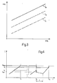
- Figure 3 shows the relationship between the pressure difference ⁇ p2 measured across the venturi device 6 and the pressure difference ⁇ p1 measured across the filter 1 or 2, for three different decreasing clogging levels Ia, Ib, Ic of particulate trapped in the filter 1 or 2.
- the relationship is not linear as shown in Figure 3, in that the straight line segments shown in this figure are obtained by a multiple linear regression operation on a large number of measurements. It is in any event reasonable to consider that the clogging level of each filter 1 or 2 can be evaluated with good approximation simply by measuring the said values ⁇ p1 and ⁇ p2.
- Figure 4 shows the variation in clogging with time for two operating conditions.
- the first condition can be considered as the norm, in that the clogging increases progressively with time to provide a monotone increasing function which intercepts the maximum regeneration threshold Smax at time tr to initiate intentional regeneration at that moment.
- the second condition involves spontaneous regeneration at time t1 which, as specified hereinafter, results in the exhaust gas flow being switched to the other filter for a time T (which terminates when spontaneous regeneration or intentional regeneration takes place in said other filter), the regeneration threshold being reduced to the value S1 (less than Smax), and subsequent intentional regeneration at time tr1, with reinstatement of the value Smax as regeneration threshold.
- the operation starts with a block 60 which reads the data provided by the sensors, 31, 32, 33, 34, after which comes a comparison block 61 which checks if the temperature T measured by the sensor 34 is greater than a predetermined minimum value Tm.
- the program passes to a comparison block 62, which checks if the absolute value of the subtraction of ⁇ p1 and ⁇ p2 from ⁇ p3 is greater than a small predetermined value indicated by A. If the result is positive, this signifies that the data provided by at least one of the sensors 31, 32, 33, is in error, so that the program passes to a block 63 which indicates a fault in the system and lights the lamp 55. If the result is negative, the program passes to the evaluation of clogging (for example of the filter 1) by block 64.
- Block 64 and the next block 65 calculate the clogging of the filter 1 at times N-1 and N to provide two values indicated by IN-1 and IN.
- a block 66 is then reached to check if the last calculated clogging value (IN) is greater than the preceding (IN-1).
- the program passes to a block 70 which sets the counter content K to K+1.
- a plurality of comparison blocks 71, 72, ....79 are traversed to reach a respective command block 81, 82,....89, which progressively lowers the value of the regeneration limit threshold to S1, S2,....Sn respectively.
- the program passes directly to a block 90 for initiating regeneration of the filter 1 in the same manner as described with reference to said block 69, to then pass to a block 90a which reinstates Smax as the regeneration threshold value.
- the program passes from the blocks 81, etc89 and from the block 90a to a block 91, which zeroes the value relative to the clogging of the filter 1.
- the block 91 is also reached from the block 69 after passing through a block 69a which reinstates Smax as the regeneration threshold.
- the program passes from block 91 to a block 92, which causes a signal to he fed to the terminal 15 of the unit 50 to switch over the solenoid valves 13, 14 and consequently deviate the exhaust gas from the engine 3 to the filter 2.
- a comparison block 93 checks whether the filter 2 is connected and remains in a waiting state passing through a timer block 94 to execute the same check periodically.
- the unit 50 also checks constantly whether the time period which has passed from the last regeneration command lies between a minimum value and a maximum value, and if it does not the unit provides a fault signal for example to light the indicator lamp 55.
- the progressive lowering of the intervention threshold eliminates the problems caused by spontaneous regeneration.
- Arranging the sensors in the container 35 and enabling the data provided by them to be used only when the temperature reaches an optimum value means that the sensors can be used over that part of their characteristic curve of greatest accuracy, with undoubted advantages from the point of view of most favourable overall management of regeneration.
- the presence of the third sensor 33 enables any casual or systematic errors in the measurement of the various pressure differences to be identified, so further improving reliability.
- the engine could be configured with a single particulate filter provided with a by-pass, or could comprise several filters connected in parallel, provided the aforesaid concept is respected.
Landscapes
- Engineering & Computer Science (AREA)
- Chemical & Material Sciences (AREA)
- Combustion & Propulsion (AREA)
- Mechanical Engineering (AREA)
- General Engineering & Computer Science (AREA)
- Processes For Solid Components From Exhaust (AREA)
Claims (10)
- Verfahren zur Steuerung der Regeneration wenigstens eines Partikelfilters (1,2), das in einer Dieselmaschine installiert ist, bei dem das Maß der Verstopfung des Filters (1,2), die durch zunehmende Ansammlung von Partikeln im Filter verursacht ist, periodisch berechnet wird, und bei dem eine innere Regeneration (69,90) des Filtes (1,2) verursacht wird, wenn das Maß der Verstopfung einen vorgegebenen oberen Verstopfungsgrenzwert (68) erreicht, gekennzeichnet durch- ein periodisches Vergleichen (66) des zuletzt berechneten Verstopfungsmaßes mit dem zuvor berechneten Verstopfungsmaß nach der beabsichtigen Regeneration (69,90);- und Definieren eines neuen oberen Verstopfungsgrenzwertes (81,89), der zunehmend niedriger ist als der zuvor definierte obere Verstopfungsgrenzwert, jeweils wenn der Vergleich eine Reduktion des Verstopfungsmaßes (81,89) zeigt.
- Verfahren nach Anspruch 1, dadurch gekennzeichnet, daß eine andere beabsichtigte Regeneration (90) verursacht wird, wenn eine vorgegebene Anzahl (n) von aufeinander folgenden Reduktionen im Verstopfungsmaß bei aufeinander folgenden Vergleichen (66) nach der vorhergehenden beabsichtigten Regeneration (69,90) festgestellt worden ist.
- Verfahren nach Anspruch 2, gekennzeichnet durch Wiederherstellen (69a,90a) des vorgegebenen oberen Verstopfungsgrenzwertes und Auf-Null-Setzen (91) des berechneten Maßes der Verstopfung nach jeder beabsichtigten Regeneration (69,90).
- Verfahren nach einem der vorhergehenden Ansprüche, gekennzeichnet durch Prüfen des Zeitintervalls zwischen zwei aufeinander folgenden, beabsichtigten Regenerationen (69,90), Vergleichen des Zeitintervalls mit einem Mindestzeit-Schwellenwert und einem Höchstzeit-Schwellenwert, und Anzeigen eines Fehlers, wenn das Zeitintervall nicht zwischen diesen Zeit-Schwellenwerten liegt.
- Vorrichtung zur Steuerung der Regeneration von wenigstens einem Partikelfilter (1,2), das in einer Dieselmaschine installiert ist, gemäß dem Verfahren des Anspruchs 1, mit einer Einrichtung (31,32,33) zum Messen der Mengen, die die Verstopfung des Filters (1,2) durch Partikel bewirken, einer Einrichtung (50) zum Verarbeiten der Mengen und Berechnen des Maßes der Verstopfung des Filters (1,2) durch zunehmende Ansammlung der Partikel, einer Einrichtung zum Speichern eines vorgegebenen oberen Verstopfungs-Schwellenwertes für das Filter (1,2), und einer Regenerations-Einrichtung (21,22), die für eine beabsichtigte Regeneration des Filters (1,2) angesteuert wird, wenn das Verstopfungsmaß den vorgegebenen Verstopfungs-Schwellenwert überschreitet, gekennzeichnet durch eine Vergleichs-Einrichtung (50) zum periodischen Vergleichen des letzten Verstopfungsmaßes, das durch die Verarbeitungseinrichtung berechnet worden ist, mit dem früheren Verstopfungsmaß nach der beabsichtigten Regeneration, und eine Steuereinrichtung (50), die auf die Vergleichseinrichtung anspricht und bewirkt, daß die Speichereinrichtung den gespeicherten Verstopfungs-Schwellenwert durch einen neuen Verstopfungs-Schwellenwert ersetzt, der zunehmend niedriger als der zuvor gespeicherte Verstopfungs-Schwellenwert ist, und zwar jeweils dann, wenn eine Reduktion des Verstopfungsmaßes entdeckt wird.
- Vorrichtung nach Anspruch 5, dadurch gekennzeichnet, daß die Steuereinrichtung (50) eine Zähleinrichtung zum Zählen der Anzahl der aufeinander folgenden Reduktionen des Zählmaßes, die nicht aus der beabsichtigten Regeneration resultiert sind, umfaßt, welche Steuereinrichtung (5) die Regenerationseinrichtung (21) für eine weitere beabsichtigte Regeneration ansteuert, wenn die Anzahl einen vorgegebenen Wert überschreitet.
- Vorrichtung nach Anspruch 6, dadurch gekennzeichnet, daß die Steuereinrichtung (50) beim Ansteuern einer beabsichtigten Regeneration auch die Speichereinrichtung ansteuert, so daß diese den vorgegebenen Verstopfungs-Schwellenwert wiederherstellt und die Verarbeitungseinrichtung einen Null-Wert für die Verstopfungsmessung anschließend an die beabsichtigte Regeneration liefert.
- Vorrichtung nach einem der Ansprüche 5 bis 7, bei der die Meßeinrichtung (31,32,33) einen ersten Druckdifferenzsensor (31), der zwischen dem Einlaß und dem Auslaß des Filters (1,2) angeordnet ist, umfaßt, wobei eine Venturi-Einrichtung (6) stromabwärts des Filters (1,2) angeordnet ist, dadurch gekennzeichnet, daß die Meßeinrichtung (31,32,33) auch einen zweiten Druckdifferenzsensor (31) aufweist, der zwischen dem Auslaß und der Venturi-Einrichtung (6) liegt, und einen dritten Druckdifferenzsensor (33), der zwischen dem Einlaß und der Venturi-Einrichtung (6) im wesentlichen parallel zu den ersten und zweiten Druckdifferenzsensoren (31,32) liegt, welche Steuereinrichtung prüft, ob wenigstens eine der Messungen der Sensoren (31,32,33) fehlerhaft arbeitet, so daß anschließend eine Fehleranzeige eingeschaltet wird.
- Vorrichtung nach Anspruch 8, gekennzeichnet durch eine Behälter-Einrichtung (35), die im Inneren die Druckdifferenzsensoren (31,32,33) aufnimmt, einen Temperatursensor (34), der in der Behälter-Einrichtung (35) angeordnet ist und dessen Temperatur abtastet, welche Verarbeitungseinrichtung (50) mit dem Temperatursensor (34) verbunden ist und die Daten der Druckdifferenzsensoren (31,32,33) nur dann abliest, wenn die Temperatur eine vorgegebene Mindesttemperatur überschreitet.
- Vorrichtung nach Anspruch 8 oder 9, bei der wenigstens zwei Filter (1,2) parallel zueinander in der Dieselmaschine angeordnet sind, und bei der gesonderte Schließeinrichtungen (13,14) stromaufwärts der Filter (1,2) angeordnet und derart gesteuert sind, daß sie die Filter (1,2) gesondert in Betrieb setzen, dadurch gekennzeichnet, daß die Venturi-Einrichtung (6) stromabwärts der beiden Filter (1,2) angeordnet ist und daß die Meßeinrichtung (31,32,33) jeweils das augenblicklich geltende Verschmutzungsmaß des Filters (1,2) mißt, welche Steuereinrichtung den Betrieb der Schließeinrichtungen (13,14) schaltet und die Filter (1,2) nacheinander bei Störung jeder der beabsichtigten Regenerationen einsetzt.
Applications Claiming Priority (2)
| Application Number | Priority Date | Filing Date | Title |
|---|---|---|---|
| IT6754088 | 1988-06-09 | ||
| IT6754088 | 1988-06-09 |
Publications (2)
| Publication Number | Publication Date |
|---|---|
| EP0349788A1 EP0349788A1 (de) | 1990-01-10 |
| EP0349788B1 true EP0349788B1 (de) | 1992-12-30 |
Family
ID=11303272
Family Applications (1)
| Application Number | Title | Priority Date | Filing Date |
|---|---|---|---|
| EP89110396A Expired - Lifetime EP0349788B1 (de) | 1988-06-09 | 1989-06-08 | Verfahren und Vorrichtung zur Steuerung der Regenerierung, wenigstens eines Partikelfilters, welches in einem Dieselmotor installiert ist |
Country Status (3)
| Country | Link |
|---|---|
| EP (1) | EP0349788B1 (de) |
| DE (1) | DE68904128T2 (de) |
| ES (1) | ES2037909T3 (de) |
Families Citing this family (14)
| Publication number | Priority date | Publication date | Assignee | Title |
|---|---|---|---|---|
| JPH0621551B2 (ja) * | 1989-06-16 | 1994-03-23 | いすゞ自動車株式会社 | パティキュレートトラップの再生装置 |
| US5063736A (en) * | 1989-08-02 | 1991-11-12 | Cummins Engine Company, Inc. | Particulate filter trap load regeneration system |
| GB2239407B (en) * | 1989-12-27 | 1994-10-12 | Nissan Motor | Exhaust gas purifying device for an internal combustion engine |
| DE4226055C1 (de) * | 1992-08-06 | 1994-09-15 | Eberspaecher J | Verfahren und Vorrichtung zur Ermittlung des Beladungszustands von Partikelfiltern |
| FR2701514B1 (fr) * | 1993-02-12 | 1995-03-24 | Renault | Procédé d'épuration par micro-ondes des gaz d'échappement de moteurs à combustion interne et dispositif de mise en Óoeuvre. |
| DE19506388C1 (de) * | 1995-02-23 | 1996-08-22 | Buero Fuer Ca Technik Dipl Ing | Verfahren zum Erkennen von systematischen Fehlern, insbesondere zur automatischen Störungserkennung bei Qualitätskontrollen, mittels mit Meßsensoren ausgestatteten Meßgeräten |
| DE19945372A1 (de) * | 1999-09-22 | 2001-03-29 | Volkswagen Ag | Verfahren zur Steuerung einer Regeneration eines Partikelfilters |
| DE10033160B4 (de) * | 2000-07-07 | 2004-06-24 | Daimlerchrysler Ag | Brennkraftmaschine, insbesondere für Kraftfahrzeuge |
| DE10223427A1 (de) * | 2002-05-25 | 2003-12-18 | Bayerische Motoren Werke Ag | Verfahren zur Regenerierung eines verstopften Partikelfilters |
| JP3985098B2 (ja) * | 2003-03-31 | 2007-10-03 | マツダ株式会社 | エンジンの制御装置 |
| FR2872214B1 (fr) | 2004-06-23 | 2006-11-03 | Peugeot Citroen Automobiles Sa | Systeme de controle de la regeneration de moyens de depollution |
| FR2872202B1 (fr) * | 2004-06-23 | 2006-11-03 | Peugeot Citroen Automobiles Sa | Systeme d'aide a la regeneration de moyens de depollution pour moteur de vehicule automobile |
| FR2872213B1 (fr) | 2004-06-23 | 2006-11-03 | Peugeot Citroen Automobiles Sa | Systeme d'aide a la regeneration de moyens de depollution pour moteur de vehicule automobile |
| CN102165151B (zh) | 2008-08-08 | 2013-06-05 | 倍耐力&C.Eco技术股份公司 | 用于控制微粒过滤器的再生的方法和设备 |
Family Cites Families (1)
| Publication number | Priority date | Publication date | Assignee | Title |
|---|---|---|---|---|
| JPS60187709A (ja) * | 1984-03-08 | 1985-09-25 | Nissan Motor Co Ltd | 内燃機関の排気微粒子処理装置 |
-
1989
- 1989-06-08 EP EP89110396A patent/EP0349788B1/de not_active Expired - Lifetime
- 1989-06-08 DE DE8989110396T patent/DE68904128T2/de not_active Expired - Fee Related
- 1989-06-08 ES ES198989110396T patent/ES2037909T3/es not_active Expired - Lifetime
Also Published As
| Publication number | Publication date |
|---|---|
| DE68904128T2 (de) | 1993-04-29 |
| DE68904128D1 (de) | 1993-02-11 |
| EP0349788A1 (de) | 1990-01-10 |
| ES2037909T3 (es) | 1993-07-01 |
Similar Documents
| Publication | Publication Date | Title |
|---|---|---|
| EP0349788B1 (de) | Verfahren und Vorrichtung zur Steuerung der Regenerierung, wenigstens eines Partikelfilters, welches in einem Dieselmotor installiert ist | |
| EP1529931B1 (de) | Filtersteuervorrichtung | |
| EP0525566B1 (de) | Verfahren und Vorrichtung zur Feststellung der Verstopfung eines Filters, insbesondere eines Filters für ein Auspuffsystem | |
| US9605578B1 (en) | Particulate matter sensing device for controlling and diagnosing diesel particulate filter systems | |
| US7272926B2 (en) | Exhaust emission control device for internal combustion engine | |
| US6176896B1 (en) | Process and device for local and controlled regeneration of a particle filter | |
| US6952953B2 (en) | Method and device for monitoring a sensor | |
| JP2877406B2 (ja) | 失火を識別する方法及び装置 | |
| CN114876618B (zh) | Dpf压差传感器测量值的修正方法、装置及存储介质 | |
| US4986069A (en) | Engine exhaust particle trap captured mass sensor | |
| JPH0318614A (ja) | パティキュレートトラップの再生装置 | |
| JP3598572B2 (ja) | 排気微粒子浄化装置 | |
| JP4226007B2 (ja) | 内燃機関に用いられる排ガス浄化装置および該排ガス浄化装置を運転するための方法 | |
| US4522028A (en) | Regenerative burner control apparatus | |
| EP3390789B1 (de) | Verfahren und anordnung zur korrektur eines fehlers von partikelmaterialsensoren | |
| JPH04325707A (ja) | 内燃機関の排気浄化装置 | |
| CN112443380B (zh) | 用于借助于颗粒传感器来监控颗粒过滤器的方法 | |
| JPS60108520A (ja) | 内燃機関の微粒子捕集量検出装置 | |
| JPH0710017Y2 (ja) | パーティキュレイトフィルタの再生装置 | |
| JPH04272419A (ja) | 内燃機関のフィルタ再生制御装置 | |
| JP4483393B2 (ja) | 排気浄化装置 | |
| JP2842128B2 (ja) | 排気ガス後処理装置の排気ガス漏れ検知装置 | |
| JPS59113232A (ja) | 排気微粒子処理装置の作動制御装置 | |
| JP3557709B2 (ja) | 内燃機関の排気微粒子捕集用トラップの再生装置及びその 再生時期検出方法 | |
| JP2536561B2 (ja) | パティキュレ―トトラップの再燃焼装置 |
Legal Events
| Date | Code | Title | Description |
|---|---|---|---|
| PUAI | Public reference made under article 153(3) epc to a published international application that has entered the european phase |
Free format text: ORIGINAL CODE: 0009012 |
|
| AK | Designated contracting states |
Kind code of ref document: A1 Designated state(s): DE ES FR GB IT NL SE |
|
| 17P | Request for examination filed |
Effective date: 19900620 |
|
| 17Q | First examination report despatched |
Effective date: 19910411 |
|
| GRAA | (expected) grant |
Free format text: ORIGINAL CODE: 0009210 |
|
| AK | Designated contracting states |
Kind code of ref document: B1 Designated state(s): DE ES FR GB IT NL SE |
|
| ITF | It: translation for a ep patent filed | ||
| REF | Corresponds to: |
Ref document number: 68904128 Country of ref document: DE Date of ref document: 19930211 |
|
| ET | Fr: translation filed | ||
| REG | Reference to a national code |
Ref country code: ES Ref legal event code: FG2A Ref document number: 2037909 Country of ref document: ES Kind code of ref document: T3 |
|
| PLBE | No opposition filed within time limit |
Free format text: ORIGINAL CODE: 0009261 |
|
| STAA | Information on the status of an ep patent application or granted ep patent |
Free format text: STATUS: NO OPPOSITION FILED WITHIN TIME LIMIT |
|
| 26N | No opposition filed | ||
| EAL | Se: european patent in force in sweden |
Ref document number: 89110396.2 |
|
| REG | Reference to a national code |
Ref country code: GB Ref legal event code: IF02 |
|
| PGFP | Annual fee paid to national office [announced via postgrant information from national office to epo] |
Ref country code: NL Payment date: 20030528 Year of fee payment: 15 |
|
| PGFP | Annual fee paid to national office [announced via postgrant information from national office to epo] |
Ref country code: SE Payment date: 20030530 Year of fee payment: 15 Ref country code: GB Payment date: 20030530 Year of fee payment: 15 Ref country code: FR Payment date: 20030530 Year of fee payment: 15 |
|
| PGFP | Annual fee paid to national office [announced via postgrant information from national office to epo] |
Ref country code: ES Payment date: 20030616 Year of fee payment: 15 |
|
| PGFP | Annual fee paid to national office [announced via postgrant information from national office to epo] |
Ref country code: DE Payment date: 20030627 Year of fee payment: 15 |
|
| PG25 | Lapsed in a contracting state [announced via postgrant information from national office to epo] |
Ref country code: GB Free format text: LAPSE BECAUSE OF NON-PAYMENT OF DUE FEES Effective date: 20040608 |
|
| PG25 | Lapsed in a contracting state [announced via postgrant information from national office to epo] |
Ref country code: SE Free format text: LAPSE BECAUSE OF NON-PAYMENT OF DUE FEES Effective date: 20040609 Ref country code: ES Free format text: LAPSE BECAUSE OF NON-PAYMENT OF DUE FEES Effective date: 20040609 |
|
| PG25 | Lapsed in a contracting state [announced via postgrant information from national office to epo] |
Ref country code: NL Free format text: LAPSE BECAUSE OF NON-PAYMENT OF DUE FEES Effective date: 20050101 Ref country code: DE Free format text: LAPSE BECAUSE OF NON-PAYMENT OF DUE FEES Effective date: 20050101 |
|
| GBPC | Gb: european patent ceased through non-payment of renewal fee |
Effective date: 20040608 |
|
| EUG | Se: european patent has lapsed | ||
| EUG | Se: european patent has lapsed | ||
| PG25 | Lapsed in a contracting state [announced via postgrant information from national office to epo] |
Ref country code: FR Free format text: LAPSE BECAUSE OF NON-PAYMENT OF DUE FEES Effective date: 20050228 |
|
| NLV4 | Nl: lapsed or anulled due to non-payment of the annual fee |
Effective date: 20050101 |
|
| REG | Reference to a national code |
Ref country code: FR Ref legal event code: ST |
|
| PG25 | Lapsed in a contracting state [announced via postgrant information from national office to epo] |
Ref country code: IT Free format text: LAPSE BECAUSE OF NON-PAYMENT OF DUE FEES Effective date: 20050608 |
|
| REG | Reference to a national code |
Ref country code: ES Ref legal event code: FD2A Effective date: 20040609 |