EP0349788B1 - Method and apparatus for controlling the regeneration of at least one particulate filter installed in a diesel engine - Google Patents
Method and apparatus for controlling the regeneration of at least one particulate filter installed in a diesel engine Download PDFInfo
- Publication number
- EP0349788B1 EP0349788B1 EP89110396A EP89110396A EP0349788B1 EP 0349788 B1 EP0349788 B1 EP 0349788B1 EP 89110396 A EP89110396 A EP 89110396A EP 89110396 A EP89110396 A EP 89110396A EP 0349788 B1 EP0349788 B1 EP 0349788B1
- Authority
- EP
- European Patent Office
- Prior art keywords
- clogging
- regeneration
- filter
- intentional
- level
- Prior art date
- Legal status (The legal status is an assumption and is not a legal conclusion. Google has not performed a legal analysis and makes no representation as to the accuracy of the status listed.)
- Expired - Lifetime
Links
Images


Classifications
-
- F—MECHANICAL ENGINEERING; LIGHTING; HEATING; WEAPONS; BLASTING
- F01—MACHINES OR ENGINES IN GENERAL; ENGINE PLANTS IN GENERAL; STEAM ENGINES
- F01N—GAS-FLOW SILENCERS OR EXHAUST APPARATUS FOR MACHINES OR ENGINES IN GENERAL; GAS-FLOW SILENCERS OR EXHAUST APPARATUS FOR INTERNAL-COMBUSTION ENGINES
- F01N3/00—Exhaust or silencing apparatus having means for purifying, rendering innocuous, or otherwise treating exhaust
- F01N3/02—Exhaust or silencing apparatus having means for purifying, rendering innocuous, or otherwise treating exhaust for cooling, or for removing solid constituents of, exhaust
- F01N3/021—Exhaust or silencing apparatus having means for purifying, rendering innocuous, or otherwise treating exhaust for cooling, or for removing solid constituents of, exhaust by means of filters
- F01N3/031—Exhaust or silencing apparatus having means for purifying, rendering innocuous, or otherwise treating exhaust for cooling, or for removing solid constituents of, exhaust by means of filters having means for by-passing filters, e.g. when clogged or during cold engine start
- F01N3/032—Exhaust or silencing apparatus having means for purifying, rendering innocuous, or otherwise treating exhaust for cooling, or for removing solid constituents of, exhaust by means of filters having means for by-passing filters, e.g. when clogged or during cold engine start during filter regeneration only
-
- F—MECHANICAL ENGINEERING; LIGHTING; HEATING; WEAPONS; BLASTING
- F01—MACHINES OR ENGINES IN GENERAL; ENGINE PLANTS IN GENERAL; STEAM ENGINES
- F01N—GAS-FLOW SILENCERS OR EXHAUST APPARATUS FOR MACHINES OR ENGINES IN GENERAL; GAS-FLOW SILENCERS OR EXHAUST APPARATUS FOR INTERNAL-COMBUSTION ENGINES
- F01N3/00—Exhaust or silencing apparatus having means for purifying, rendering innocuous, or otherwise treating exhaust
- F01N3/02—Exhaust or silencing apparatus having means for purifying, rendering innocuous, or otherwise treating exhaust for cooling, or for removing solid constituents of, exhaust
- F01N3/021—Exhaust or silencing apparatus having means for purifying, rendering innocuous, or otherwise treating exhaust for cooling, or for removing solid constituents of, exhaust by means of filters
- F01N3/023—Exhaust or silencing apparatus having means for purifying, rendering innocuous, or otherwise treating exhaust for cooling, or for removing solid constituents of, exhaust by means of filters using means for regenerating the filters, e.g. by burning trapped particles
-
- F—MECHANICAL ENGINEERING; LIGHTING; HEATING; WEAPONS; BLASTING
- F01—MACHINES OR ENGINES IN GENERAL; ENGINE PLANTS IN GENERAL; STEAM ENGINES
- F01N—GAS-FLOW SILENCERS OR EXHAUST APPARATUS FOR MACHINES OR ENGINES IN GENERAL; GAS-FLOW SILENCERS OR EXHAUST APPARATUS FOR INTERNAL-COMBUSTION ENGINES
- F01N9/00—Electrical control of exhaust gas treating apparatus
- F01N9/002—Electrical control of exhaust gas treating apparatus of filter regeneration
-
- F—MECHANICAL ENGINEERING; LIGHTING; HEATING; WEAPONS; BLASTING
- F01—MACHINES OR ENGINES IN GENERAL; ENGINE PLANTS IN GENERAL; STEAM ENGINES
- F01N—GAS-FLOW SILENCERS OR EXHAUST APPARATUS FOR MACHINES OR ENGINES IN GENERAL; GAS-FLOW SILENCERS OR EXHAUST APPARATUS FOR INTERNAL-COMBUSTION ENGINES
- F01N2390/00—Arrangements for controlling or regulating exhaust apparatus
- F01N2390/02—Arrangements for controlling or regulating exhaust apparatus using electric components only
-
- F—MECHANICAL ENGINEERING; LIGHTING; HEATING; WEAPONS; BLASTING
- F02—COMBUSTION ENGINES; HOT-GAS OR COMBUSTION-PRODUCT ENGINE PLANTS
- F02B—INTERNAL-COMBUSTION PISTON ENGINES; COMBUSTION ENGINES IN GENERAL
- F02B3/00—Engines characterised by air compression and subsequent fuel addition
- F02B3/06—Engines characterised by air compression and subsequent fuel addition with compression ignition
-
- Y—GENERAL TAGGING OF NEW TECHNOLOGICAL DEVELOPMENTS; GENERAL TAGGING OF CROSS-SECTIONAL TECHNOLOGIES SPANNING OVER SEVERAL SECTIONS OF THE IPC; TECHNICAL SUBJECTS COVERED BY FORMER USPC CROSS-REFERENCE ART COLLECTIONS [XRACs] AND DIGESTS
- Y02—TECHNOLOGIES OR APPLICATIONS FOR MITIGATION OR ADAPTATION AGAINST CLIMATE CHANGE
- Y02T—CLIMATE CHANGE MITIGATION TECHNOLOGIES RELATED TO TRANSPORTATION
- Y02T10/00—Road transport of goods or passengers
- Y02T10/10—Internal combustion engine [ICE] based vehicles
- Y02T10/40—Engine management systems
Definitions
- This invention relates to a method and apparatus controlling the regeneration of at least one particulate filter installed in a diesel engine of non-supercharged or supercharged type.
- triggering and controlling the combustion of particles which have accumulated within a particulate filter are still the two major problems to be solved in the development of an efficient filtration system for the exhaust gas of a diesel engine.
- the periodical process of oxidising the trapped carbon particles commonly known by the term regeneration, is necessary in order to maintain the back pressure on the engine exhaust at an acceptable level.
- regeneration control is necessary to prevent excessive temperature being reached during particulate combustion, with possible destruction of the filter.
- Regeneration is effected in various ways, but generally by operating thermal energy generators (burners etc.) when it is considered that the clogging of the filter has reached a suitable level between a maximum and a minimum limit.
- the maximum limit is determined, as stated, by the need to avoid both excessive back pressure on the engine exhaust, with unacceptable deterioration in performance, and too high temperature during regeneration, which could lead to breakage of the filter.
- More critical is the required minimum amount of particulate which has to be accumulated before regeneration can be initiated. If the quantity of particulate trapped in the filter is small there would certainly be no excess temperature, but in this case combustion would not be complete as the propagation of the flame front, for example in the last part of a ceramic filter, is sustained by the thermal energy released by the combustion of the carbon particles of the particulate.
- the object of the present invention is to provide a method and apparatus for controlling the regeneration of particulate filters for diesel engines which obviate the aforesaid drawbacks of the current systems.
- Said object is attained according to the present invention by a method controlling the regeneration of at least one particulate filter installed in a diesel engine, wherein the level of clogging of said filter caused by progressive accumulation therein of the particulate is periodically calculated, and wherein an intentional regeneration of said filter is caused when said clogging level reaches a predetermined upper clogging limit, characterized by
- a device controlling the regeneration of at least one particulate filter installed in a diesel engine comprising means for measuring quantities related to the clogging of said filter by said particulate, means for processing said quantities and calculating the level of clogging of said filter caused by the progressive accumulation of said particulate, means for memorizing a predetermined upper clogging threshold for said filter, and regeneration means adapted to be controlled for an intentional regeneration of said filter when said level of clogging exceeds said predetermined clogging threshold, characterized by comparing means for periodically comparing the last clogging level calculated by said processing means with the previous calculated clogging level after said intentional regeneration, and control means responsive to said comparing means for causing said memorizing means to replace the memorized clogging threshold with a new clogging threshold progressively lower than the previously memorized clogging threshold each time a reduction of said clogging level is revealed.
- the reference numeral 10 indicates overall an apparatus for controlling the regeneration of two filters 1 and 2 for the particulate present in the exhaust gas of a diesel engine 3.
- the filters 1 and 2 are substantially connected in parallel and are interposed between an exhaust gas collection pipe 5 disposed immediately downstream of the engine 3 and a venturi device 6 which is connected to a further pipe 7 carrying the exhaust gas.
- the pipe 5 comprises two branches 11 and 12 which lead respectively to the filters 1 and 2 and into which there are connected solenoid valves 13 and 14 activated in opposition by an an electrical signal reaching a terminal 15 and which, in the case only of the solenoid valve 13, is negated by an inverting gate 16.
- each filter 1, 2 (consisting for example of a monolithic ceramic element) is provided with a respective burner (with its control system) 21, 22 of conventional type.
- Each burner 21, 22 is connected both to a first terminal 23, 24 from which it receives a corresponding activation signal, and to a second terminal 25, 26, to which it transmits a corresponding control signal usable to indicate whether the burner and relative control system are active or not.
- a first pressure difference sensor 31 is installed across the filters 1 and 2
- a second pressure difference sensor 32 is installed between the outlets of the filters and the venturi device 6
- a third pressure difference sensor 33 is installed between the inlets to the filters 1 and 2 (upstream of the solenoid valves 13 and 14) and the venturi device 6.
- the sensors 31, 32, 33 are enclosed, together with a temperature sensor 34, within a container 35 to keep them all at the same temperature (read by the sensor 34).
- the sensors 31, 32, 33, 34 generate respective signals which are fed to corresponding terminals 41, 42, 43, 44.
- the apparatus 10 also comprises a processing and computing unit 50 (conveniently provided with a microprocessor) having a plurality of input and output terminals indicated by the same reference numerals as said terminals, to which they are connected in a manner not shown.
- a processing and computing unit 50 (conveniently provided with a microprocessor) having a plurality of input and output terminals indicated by the same reference numerals as said terminals, to which they are connected in a manner not shown.
- the unit 50 comprises a further five outputs connected to respective indicator lamps 51, 52, 53, 54, 55 which are activated respectively in the following case: lamp 51: filter 1 connected lamp 52: filter 2 connected lamp 53: filter 1 undergoing regeneration lamp 54: filter 2 undergoing regeneration lamp 55: fault situation.
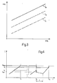
- Figure 3 shows the relationship between the pressure difference ⁇ p2 measured across the venturi device 6 and the pressure difference ⁇ p1 measured across the filter 1 or 2, for three different decreasing clogging levels Ia, Ib, Ic of particulate trapped in the filter 1 or 2.
- the relationship is not linear as shown in Figure 3, in that the straight line segments shown in this figure are obtained by a multiple linear regression operation on a large number of measurements. It is in any event reasonable to consider that the clogging level of each filter 1 or 2 can be evaluated with good approximation simply by measuring the said values ⁇ p1 and ⁇ p2.
- Figure 4 shows the variation in clogging with time for two operating conditions.
- the first condition can be considered as the norm, in that the clogging increases progressively with time to provide a monotone increasing function which intercepts the maximum regeneration threshold Smax at time tr to initiate intentional regeneration at that moment.
- the second condition involves spontaneous regeneration at time t1 which, as specified hereinafter, results in the exhaust gas flow being switched to the other filter for a time T (which terminates when spontaneous regeneration or intentional regeneration takes place in said other filter), the regeneration threshold being reduced to the value S1 (less than Smax), and subsequent intentional regeneration at time tr1, with reinstatement of the value Smax as regeneration threshold.
- the operation starts with a block 60 which reads the data provided by the sensors, 31, 32, 33, 34, after which comes a comparison block 61 which checks if the temperature T measured by the sensor 34 is greater than a predetermined minimum value Tm.
- the program passes to a comparison block 62, which checks if the absolute value of the subtraction of ⁇ p1 and ⁇ p2 from ⁇ p3 is greater than a small predetermined value indicated by A. If the result is positive, this signifies that the data provided by at least one of the sensors 31, 32, 33, is in error, so that the program passes to a block 63 which indicates a fault in the system and lights the lamp 55. If the result is negative, the program passes to the evaluation of clogging (for example of the filter 1) by block 64.
- Block 64 and the next block 65 calculate the clogging of the filter 1 at times N-1 and N to provide two values indicated by IN-1 and IN.
- a block 66 is then reached to check if the last calculated clogging value (IN) is greater than the preceding (IN-1).
- the program passes to a block 70 which sets the counter content K to K+1.
- a plurality of comparison blocks 71, 72, ....79 are traversed to reach a respective command block 81, 82,....89, which progressively lowers the value of the regeneration limit threshold to S1, S2,....Sn respectively.
- the program passes directly to a block 90 for initiating regeneration of the filter 1 in the same manner as described with reference to said block 69, to then pass to a block 90a which reinstates Smax as the regeneration threshold value.
- the program passes from the blocks 81, etc89 and from the block 90a to a block 91, which zeroes the value relative to the clogging of the filter 1.
- the block 91 is also reached from the block 69 after passing through a block 69a which reinstates Smax as the regeneration threshold.
- the program passes from block 91 to a block 92, which causes a signal to he fed to the terminal 15 of the unit 50 to switch over the solenoid valves 13, 14 and consequently deviate the exhaust gas from the engine 3 to the filter 2.
- a comparison block 93 checks whether the filter 2 is connected and remains in a waiting state passing through a timer block 94 to execute the same check periodically.
- the unit 50 also checks constantly whether the time period which has passed from the last regeneration command lies between a minimum value and a maximum value, and if it does not the unit provides a fault signal for example to light the indicator lamp 55.
- the progressive lowering of the intervention threshold eliminates the problems caused by spontaneous regeneration.
- Arranging the sensors in the container 35 and enabling the data provided by them to be used only when the temperature reaches an optimum value means that the sensors can be used over that part of their characteristic curve of greatest accuracy, with undoubted advantages from the point of view of most favourable overall management of regeneration.
- the presence of the third sensor 33 enables any casual or systematic errors in the measurement of the various pressure differences to be identified, so further improving reliability.
- the engine could be configured with a single particulate filter provided with a by-pass, or could comprise several filters connected in parallel, provided the aforesaid concept is respected.
Landscapes
- Engineering & Computer Science (AREA)
- Chemical & Material Sciences (AREA)
- Combustion & Propulsion (AREA)
- Mechanical Engineering (AREA)
- General Engineering & Computer Science (AREA)
- Processes For Solid Components From Exhaust (AREA)
Description
- This invention relates to a method and apparatus controlling the regeneration of at least one particulate filter installed in a diesel engine of non-supercharged or supercharged type.
- As is well known, triggering and controlling the combustion of particles which have accumulated within a particulate filter (also known familiarly as a trap) are still the two major problems to be solved in the development of an efficient filtration system for the exhaust gas of a diesel engine. In this respect, the periodical process of oxidising the trapped carbon particles, commonly known by the term regeneration, is necessary in order to maintain the back pressure on the engine exhaust at an acceptable level. In the same manner, regeneration control is necessary to prevent excessive temperature being reached during particulate combustion, with possible destruction of the filter.
- Regeneration is effected in various ways, but generally by operating thermal energy generators (burners etc.) when it is considered that the clogging of the filter has reached a suitable level between a maximum and a minimum limit.
- The maximum limit is determined, as stated, by the need to avoid both excessive back pressure on the engine exhaust, with unacceptable deterioration in performance, and too high temperature during regeneration, which could lead to breakage of the filter.
- More critical is the required minimum amount of particulate which has to be accumulated before regeneration can be initiated. If the quantity of particulate trapped in the filter is small there would certainly be no excess temperature, but in this case combustion would not be complete as the propagation of the flame front, for example in the last part of a ceramic filter, is sustained by the thermal energy released by the combustion of the carbon particles of the particulate.
- It often happens that regeneration is triggered spontaneously when the quantity of particulate has not yet reached the aforesaid minimum level, so that combustion is not sustained. Thus at the end of regeneration there still remains particulate in the last part of the filter, this particulate then being added to that which collects during the next accumulation period. The initiation of the next regeneration on the basis of an average clogging evaluation could lead to irreversible damage to the filter. This is because the particulate will have accumulated to a larger extent in certain zones of the filter, with consequent greater development of thermal energy deriving from the combustion of the particulate.
- A further drawback of current regeneration control systems is that the evaluation of the filter clogging is done by instruments the measurements of which could be affected by systematic errors or by errors consequent on particular environmental conditions such as the temperature at which the reading is taken. It is apparent that this situation can lead to the regeneration being initiated either early or late, leading to all the aforementioned consequences.
- From the US-A-4 603 550, it is also known an exhaust particilate removing system, wherein the regeneration of the filter is effected by operating a burner controlled by a control unit in response of a signal corresponding to the difference of pressure between the inlet and the outlet, a signal of the temperature within the burner, and other signals of the operating conditions of the engine.
- The object of the present invention is to provide a method and apparatus for controlling the regeneration of particulate filters for diesel engines which obviate the aforesaid drawbacks of the current systems.
- Said object is attained according to the present invention by a method controlling the regeneration of at least one particulate filter installed in a diesel engine, wherein the level of clogging of said filter caused by progressive accumulation therein of the particulate is periodically calculated, and wherein an intentional regeneration of said filter is caused when said clogging level reaches a predetermined upper clogging limit, characterized by
- periodically comparing the last calculated clogging level with the previous calculated clogging level after said intentional regeneration;
- and defining a new upper clogging limit progressively lower than the previously defined upper clogging limit each time said comparison reveals a reduction of said clogging level.
- Said object is further attained according to the present invention by a device controlling the regeneration of at least one particulate filter installed in a diesel engine, according to the above method, comprising means for measuring quantities related to the clogging of said filter by said particulate, means for processing said quantities and calculating the level of clogging of said filter caused by the progressive accumulation of said particulate, means for memorizing a predetermined upper clogging threshold for said filter, and regeneration means adapted to be controlled for an intentional regeneration of said filter when said level of clogging exceeds said predetermined clogging threshold, characterized by comparing means for periodically comparing the last clogging level calculated by said processing means with the previous calculated clogging level after said intentional regeneration, and control means responsive to said comparing means for causing said memorizing means to replace the memorized clogging threshold with a new clogging threshold progressively lower than the previously memorized clogging threshold each time a reduction of said clogging level is revealed.
- The present invention will be more apparent from the description of a preferred embodiment thereof given hereinafter by way of non-limiting example with reference to the accompanying drawings in which:
- Figure 1 is a simplified block diagram of an apparatus constructed in accordance with the present invention and shown in one example of application;
- Figure 2 is a flow diagram representing a sequence of operations effected by the apparatus of Figure 1 under the control of a processing unit of the apparatus;
- Figure 3 shows the relationship between two quantities measured by respective instruments of the apparatus of Figure 1 under different conditions; and
- Figure 4 shows two examples of the action of the apparatus of Figure 1 under two different operating conditions.
- In Figure 1, the
reference numeral 10 indicates overall an apparatus for controlling the regeneration of twofilters diesel engine 3. Thefilters engine 3 and a venturi device 6 which is connected to afurther pipe 7 carrying the exhaust gas. - The pipe 5 comprises two
branches filters solenoid valves 13 and 14 activated in opposition by an an electrical signal reaching aterminal 15 and which, in the case only of the solenoid valve 13, is negated by an inverting gate 16. eachfilter 1, 2 (consisting for example of a monolithic ceramic element) is provided with a respective burner (with its control system) 21, 22 of conventional type. - Each burner 21, 22 is connected both to a
first terminal second terminal - A first pressure difference sensor 31 is installed across the
filters pressure difference sensor 32 is installed between the outlets of the filters and the venturi device 6, and a thirdpressure difference sensor 33 is installed between the inlets to thefilters 1 and 2 (upstream of the solenoid valves 13 and 14) and the venturi device 6. - The
sensors temperature sensor 34, within acontainer 35 to keep them all at the same temperature (read by the sensor 34). Thesensors corresponding terminals - The
apparatus 10 also comprises a processing and computing unit 50 (conveniently provided with a microprocessor) having a plurality of input and output terminals indicated by the same reference numerals as said terminals, to which they are connected in a manner not shown. - The
unit 50 comprises a further five outputs connected torespective indicator lamps
lamp 51:filter 1 connected
lamp 52:filter 2 connected
lamp 53:filter 1 undergoing regeneration
lamp 54:filter 2 undergoing regeneration
lamp 55: fault situation. - Figure 3 shows the relationship between the pressure difference Δp2 measured across the venturi device 6 and the pressure difference Δp1 measured across the
filter filter filter - Figure 4 shows the variation in clogging with time for two operating conditions.
- The first condition can be considered as the norm, in that the clogging increases progressively with time to provide a monotone increasing function which intercepts the maximum regeneration threshold Smax at time tr to initiate intentional regeneration at that moment.
- The second condition involves spontaneous regeneration at time t1 which, as specified hereinafter, results in the exhaust gas flow being switched to the other filter for a time T (which terminates when spontaneous regeneration or intentional regeneration takes place in said other filter), the regeneration threshold being reduced to the value S1 (less than Smax), and subsequent intentional regeneration at time tr1, with reinstatement of the value Smax as regeneration threshold.
- The operation of the
apparatus 10 is described hereinafter in detail with reference to Figure 2. - The operation starts with a
block 60 which reads the data provided by the sensors, 31, 32, 33, 34, after which comes acomparison block 61 which checks if the temperature T measured by thesensor 34 is greater than a predetermined minimum value Tm. - If the result is negative, the procedure returns to the input of
block 60 to prevent processing of the data provided by the other sensors, which are not accurate for low temperatures. - If the result is positive, the program passes to a
comparison block 62, which checks if the absolute value of the subtraction of Δp1 and Δp2 from Δp3 is greater than a small predetermined value indicated by A. If the result is positive, this signifies that the data provided by at least one of thesensors block 63 which indicates a fault in the system and lights thelamp 55. If the result is negative, the program passes to the evaluation of clogging (for example of the filter 1) byblock 64. -
Block 64 and thenext block 65 calculate the clogging of thefilter 1 at times N-1 and N to provide two values indicated by IN-1 and IN. Ablock 66 is then reached to check if the last calculated clogging value (IN) is greater than the preceding (IN-1). - If the result is positive, this signifies that there has been a further accumulation of particles between the two calculation times, and it is therefore necessary to check whether the maximum clogging value (Smax) has been exceeded, and thus initiate regeneration, or to again execute the clogging calculation as described heretofore. This is done by passing from
block 66 toblock 67, in which N is put equal to N+1 and setting a counter K to 0, to then pass to ablock 68 for comparing IN with Imax, and then to ablock 69 for initiating regeneration of the filter 1 (by activating the burner 21 and lighting the indicator lamp 53), or again to the input ofblock 64. - If the result is negative, this signifies that partial spontaneous regeneration of the
filter 1 has occurred, and the program passes to a block 70 which sets the counter content K to K+1. Depending on the effective value assumed by the parameter K (variable for example from 1 to n), a plurality ofcomparison blocks respective command block block 90 for initiating regeneration of thefilter 1 in the same manner as described with reference to saidblock 69, to then pass to a block 90a which reinstates Smax as the regeneration threshold value. - The program passes from the
blocks 81,.....89 and from the block 90a to ablock 91, which zeroes the value relative to the clogging of thefilter 1. Theblock 91 is also reached from theblock 69 after passing through ablock 69a which reinstates Smax as the regeneration threshold. - The program passes from
block 91 to a block 92, which causes a signal to he fed to theterminal 15 of theunit 50 to switch over thesolenoid valves 13, 14 and consequently deviate the exhaust gas from theengine 3 to thefilter 2. - At this point, a
comparison block 93 checks whether thefilter 2 is connected and remains in a waiting state passing through a timer block 94 to execute the same check periodically. - If the result of the check is negative, the program returns to the input of the
computing block 64 to repeat the aforesaid cycle. - In a manner not illustrated but parallel to the aforesaid, the
unit 50 also checks constantly whether the time period which has passed from the last regeneration command lies between a minimum value and a maximum value, and if it does not the unit provides a fault signal for example to light theindicator lamp 55. - The advantages of the method and apparatus of the present invention are apparent from an examination of their characteristics.
- Firstly, the progressive lowering of the intervention threshold eliminates the problems caused by spontaneous regeneration.
- Arranging the sensors in the
container 35 and enabling the data provided by them to be used only when the temperature reaches an optimum value means that the sensors can be used over that part of their characteristic curve of greatest accuracy, with undoubted advantages from the point of view of most favourable overall management of regeneration. In addition the presence of thethird sensor 33 enables any casual or systematic errors in the measurement of the various pressure differences to be identified, so further improving reliability. - Connecting the
filters - Finally, checking the time period which has passed since the last regeneration enables operating faults which may have escaped the previous checks to be detected. For example, a too frequent request for regeneration could not be realistic as it is not possible for the particulate to accumulate in the filter in such quantity in a short time. It could instead be the case that the filter is really clogged but the apparatus is unable to detect this because the clogging calculation can give results which are lower than the true results if the
engine 3 operates at low r.p.m., the measurement across the venturi device 6 then possibly being in considerable error. - Finally, it is apparent that modifications can be made to the aforesaid method and apparatus but without leaving the scope of the claims.
- For example the engine could be configured with a single particulate filter provided with a by-pass, or could comprise several filters connected in parallel, provided the aforesaid concept is respected.
Claims (10)
- A method controlling the regeneration of at least one particulate filter (1, 2) installed in a diesel engine, wherein the level of clogging of said filter (1, 2) caused by progressive accumulation therein of the particulate is periodically calculated, and wherein an intentional regeneration (69, 90) of said filter (1, 2) is caused when said clogging level reaches a predetermined upper clogging limit (68), characterized by- periodically comparing (66) the last calculated clogging level with the previous calculated clogging level after said intentional regeneration (69, 90);- and defining a new upper clogging limit (81, 89) progressively lower than the previously defined upper clogging limit each time said comparison reveals a reduction of said clogging level (81, 89).
- A method as claimed in claim 1, characterized by causing another intentional regeneration (90) if a predetermined number (n) of consecutive reductions in said clogging level are revealed in consecutive comparisons (66) after the previous intentional regeneration (69, 90).
- A method according to claim 2, characterized by restating (69a, 90a) said predetermined upper clogging limit and zeroing (91) said calculated level of clogging after each one of said intentional regenerations (69, 90).
- A method according to any previous claim, characterized by checking the time interval passed between two consecutive intentional regenerations (69, 90), comparing said time interval with a minimum time threshold and with a maximum time threshold, and providing a fault indication if said time interval does not lies between said time thresholds.
- A device controlling the regeneration of at least one particulate filter (1, 2) installed in a diesel engine, according to the method of claim 1, comprising means (31, 32, 33) for measuring quantities related to the clogging of said filter (1, 2) by said particulate, means (50) for processing said quantities and calculating the level of clogging of said filter (1, 2) caused by the progressive accumulation of said particulate, means (50) for memorizing a predetermined upper clogging threshold for said filter (1, 2), and regeneration means (21, 22) adapted to be controlled for an intentional regeneration of said filter (1, 2) when said level of clogging exceeds said predetermined clogging threshold, characterized by comparing means (50) for periodically comparing the last clogging level calculated by said processing means with the previous calculated clogging level after said intentional regeneration, and control means (50) responsive to said comparing means for causing said memorizing means to replace the memorized clogging threshold with a new clogging threshold progressively lower than the previously memorized clogging threshold each time a reduction of said clogging level is revealed.
- A device as claimed in claim 5, characterized in that said control means (50) include counting means for counting the number of consecutive reductions in the counting level which have not resulted from said intentional regeneration, said control means (5) being adapted to control said regeneration means (21, 22) for another intentional regeneration when said number exceeds a predetermined value.
- A device as in claimed in claim 6, characterized in that said control means (50) upon controlling an intentional regeneration are also adapted to control said memorizing means to restate said predetermined clogging threshold and to cause said processing means to provide a zero value for the clogging measurement subsequent to said intentional regeneration.
- A device as claimed in any claim from 5 to 7, wherein said measuring means (31, 32, 33) include a first pressure difference sensor (31) connected between an inlet and an outlet of said filter (1, 2), and wherein a venturi device (6) is connected downstream of said filter (1, 2), characterized in that said measuring means (31, 32, 33) include also a second pressure difference sensor (31) connected between said outlet and said venturi device (6) and a third pressure difference sensor (33) connected between said inlet and said venturi device (6) substantially in parallel with said first and second pressure difference sensors (31, 32), said control means (50) being adapted to check whether at least one of the measurements supplied by said sensors (31, 32, 33) is in error and to enable consequently a fault indicator.
- A device as claimed in claim 8, characterized by container means (35) internally housing said pressure difference sensors (31, 32, 33), a temperature sensor (34) being housed in said container means (35) to sense the temperature thereof, said processing means (50) being connected with said temperature sensor (34) and being adapted for reading the data provided by said pressure difference sensors (31, 31, 33) only if said temperature exceeds a predetermined minimum temperature.
- A device as claimed in 8 or 9, wherein at least two filters (1 and 2) are installed in parallel in said diesel machine, and wherein individual shutoff means (13, 14) are installed upstream of said filters (1, 2) and are controlled for rendering said filters (1, 2) individually effective, characterized in that said venturi device (6) is connected downstream of both said filters (1, 2), and said measuring means (31, 32, 33) are adapted to measure each time the level of clogging of the filter (1, 2) presently effective, said control means (50) being adapted to switch the operation of said shutoff means (13, 14) to sequentially render said filters (1, 2) upon controlling each one of said intentional regenerations.
Applications Claiming Priority (2)
| Application Number | Priority Date | Filing Date | Title |
|---|---|---|---|
| IT6754088 | 1988-06-09 | ||
| IT6754088 | 1988-06-09 |
Publications (2)
| Publication Number | Publication Date |
|---|---|
| EP0349788A1 EP0349788A1 (en) | 1990-01-10 |
| EP0349788B1 true EP0349788B1 (en) | 1992-12-30 |
Family
ID=11303272
Family Applications (1)
| Application Number | Title | Priority Date | Filing Date |
|---|---|---|---|
| EP89110396A Expired - Lifetime EP0349788B1 (en) | 1988-06-09 | 1989-06-08 | Method and apparatus for controlling the regeneration of at least one particulate filter installed in a diesel engine |
Country Status (3)
| Country | Link |
|---|---|
| EP (1) | EP0349788B1 (en) |
| DE (1) | DE68904128T2 (en) |
| ES (1) | ES2037909T3 (en) |
Families Citing this family (14)
| Publication number | Priority date | Publication date | Assignee | Title |
|---|---|---|---|---|
| JPH0621551B2 (en) * | 1989-06-16 | 1994-03-23 | いすゞ自動車株式会社 | Particulate trap regeneration device |
| US5063736A (en) * | 1989-08-02 | 1991-11-12 | Cummins Engine Company, Inc. | Particulate filter trap load regeneration system |
| US5195316A (en) * | 1989-12-27 | 1993-03-23 | Nissan Motor Co., Ltd. | Exhaust gas purifying device for an internal combustion engine |
| DE4226055C1 (en) * | 1992-08-06 | 1994-09-15 | Eberspaecher J | Method and device for determining the loading status of particle filters |
| FR2701514B1 (en) * | 1993-02-12 | 1995-03-24 | Renault | Process for the purification by microwaves of exhaust gases from internal combustion engines and device for implementing it. |
| DE19506388C1 (en) * | 1995-02-23 | 1996-08-22 | Buero Fuer Ca Technik Dipl Ing | Method for recognizing systematic errors, in particular for the automatic detection of malfunctions in quality controls, by means of measuring devices equipped with measuring sensors |
| DE19945372A1 (en) * | 1999-09-22 | 2001-03-29 | Volkswagen Ag | Method for controlling regeneration of a particle filter |
| DE10033160B4 (en) * | 2000-07-07 | 2004-06-24 | Daimlerchrysler Ag | Internal combustion engine, in particular for motor vehicles |
| DE10223427A1 (en) * | 2002-05-25 | 2003-12-18 | Bayerische Motoren Werke Ag | Process for the regeneration of a clogged particle filter |
| JP3985098B2 (en) * | 2003-03-31 | 2007-10-03 | マツダ株式会社 | Engine control device |
| FR2872214B1 (en) | 2004-06-23 | 2006-11-03 | Peugeot Citroen Automobiles Sa | SYSTEM FOR MONITORING THE REGENERATION OF MEANS OF DEPOLLUTION |
| FR2872202B1 (en) * | 2004-06-23 | 2006-11-03 | Peugeot Citroen Automobiles Sa | EMERGENCY MEANS REGENERATION SYSTEM FOR MOTOR VEHICLE ENGINE |
| FR2872213B1 (en) | 2004-06-23 | 2006-11-03 | Peugeot Citroen Automobiles Sa | EMERGENCY MEANS REGENERATION SYSTEM FOR MOTOR VEHICLE ENGINE |
| WO2010016077A1 (en) * | 2008-08-08 | 2010-02-11 | Pirelli & C. Eco Technology S.P.A. | Method and device for controlling the regeneration of a particulate filter |
Family Cites Families (1)
| Publication number | Priority date | Publication date | Assignee | Title |
|---|---|---|---|---|
| JPS60187709A (en) * | 1984-03-08 | 1985-09-25 | Nissan Motor Co Ltd | Treater for fine particle in exhaust from internal-combustion engine |
-
1989
- 1989-06-08 ES ES198989110396T patent/ES2037909T3/en not_active Expired - Lifetime
- 1989-06-08 DE DE8989110396T patent/DE68904128T2/en not_active Expired - Fee Related
- 1989-06-08 EP EP89110396A patent/EP0349788B1/en not_active Expired - Lifetime
Also Published As
| Publication number | Publication date |
|---|---|
| ES2037909T3 (en) | 1993-07-01 |
| DE68904128T2 (en) | 1993-04-29 |
| DE68904128D1 (en) | 1993-02-11 |
| EP0349788A1 (en) | 1990-01-10 |
Similar Documents
| Publication | Publication Date | Title |
|---|---|---|
| EP0349788B1 (en) | Method and apparatus for controlling the regeneration of at least one particulate filter installed in a diesel engine | |
| EP1529931B1 (en) | Filter control device | |
| EP0525566B1 (en) | A method and apparatus for determining the clogging of a filter, in particular a filter for an exhaust system | |
| US9605578B1 (en) | Particulate matter sensing device for controlling and diagnosing diesel particulate filter systems | |
| US7272926B2 (en) | Exhaust emission control device for internal combustion engine | |
| US6176896B1 (en) | Process and device for local and controlled regeneration of a particle filter | |
| US6952953B2 (en) | Method and device for monitoring a sensor | |
| US20100180669A1 (en) | Monitoring of a particle limit value in the exhaust gas of an internal combustion engine | |
| US4986069A (en) | Engine exhaust particle trap captured mass sensor | |
| JPH04501157A (en) | Method and apparatus for identifying misfires | |
| JP3598572B2 (en) | Exhaust particulate purification equipment | |
| JP4226007B2 (en) | Exhaust gas purification device used for internal combustion engine and method for operating the exhaust gas purification device | |
| US4522028A (en) | Regenerative burner control apparatus | |
| JPH1077826A (en) | Black smoke purification device for diesel engine | |
| JPH08284644A (en) | Exhaust particulate purifying device | |
| EP3390789B1 (en) | Method and arrangement for correcting for error of particulate matter sensors | |
| JPH04325707A (en) | Exhaust gas purifying device for engine | |
| CN112443380B (en) | Method for monitoring a particle filter by means of a particle sensor | |
| JPS60108520A (en) | Device for detecting trapping amount of fine particles in internal-combustion engine | |
| JPH0710017Y2 (en) | Particulate filter playback device | |
| JPH04272419A (en) | Filter regeneration controlling device for internal combustion engine | |
| JP4483393B2 (en) | Exhaust purification device | |
| JP2842128B2 (en) | Exhaust gas leak detection device of exhaust gas aftertreatment device | |
| JPS59113232A (en) | Apparatus for controlling operation of device for treating fine particles contained in exhaust gas | |
| JP3557709B2 (en) | Apparatus for regenerating trap for collecting exhaust particulates of internal combustion engine and method for detecting regeneration time |
Legal Events
| Date | Code | Title | Description |
|---|---|---|---|
| PUAI | Public reference made under article 153(3) epc to a published international application that has entered the european phase |
Free format text: ORIGINAL CODE: 0009012 |
|
| AK | Designated contracting states |
Kind code of ref document: A1 Designated state(s): DE ES FR GB IT NL SE |
|
| 17P | Request for examination filed |
Effective date: 19900620 |
|
| 17Q | First examination report despatched |
Effective date: 19910411 |
|
| GRAA | (expected) grant |
Free format text: ORIGINAL CODE: 0009210 |
|
| AK | Designated contracting states |
Kind code of ref document: B1 Designated state(s): DE ES FR GB IT NL SE |
|
| ITF | It: translation for a ep patent filed | ||
| REF | Corresponds to: |
Ref document number: 68904128 Country of ref document: DE Date of ref document: 19930211 |
|
| ET | Fr: translation filed | ||
| REG | Reference to a national code |
Ref country code: ES Ref legal event code: FG2A Ref document number: 2037909 Country of ref document: ES Kind code of ref document: T3 |
|
| PLBE | No opposition filed within time limit |
Free format text: ORIGINAL CODE: 0009261 |
|
| STAA | Information on the status of an ep patent application or granted ep patent |
Free format text: STATUS: NO OPPOSITION FILED WITHIN TIME LIMIT |
|
| 26N | No opposition filed | ||
| EAL | Se: european patent in force in sweden |
Ref document number: 89110396.2 |
|
| REG | Reference to a national code |
Ref country code: GB Ref legal event code: IF02 |
|
| PGFP | Annual fee paid to national office [announced via postgrant information from national office to epo] |
Ref country code: NL Payment date: 20030528 Year of fee payment: 15 |
|
| PGFP | Annual fee paid to national office [announced via postgrant information from national office to epo] |
Ref country code: SE Payment date: 20030530 Year of fee payment: 15 Ref country code: GB Payment date: 20030530 Year of fee payment: 15 Ref country code: FR Payment date: 20030530 Year of fee payment: 15 |
|
| PGFP | Annual fee paid to national office [announced via postgrant information from national office to epo] |
Ref country code: ES Payment date: 20030616 Year of fee payment: 15 |
|
| PGFP | Annual fee paid to national office [announced via postgrant information from national office to epo] |
Ref country code: DE Payment date: 20030627 Year of fee payment: 15 |
|
| PG25 | Lapsed in a contracting state [announced via postgrant information from national office to epo] |
Ref country code: GB Free format text: LAPSE BECAUSE OF NON-PAYMENT OF DUE FEES Effective date: 20040608 |
|
| PG25 | Lapsed in a contracting state [announced via postgrant information from national office to epo] |
Ref country code: SE Free format text: LAPSE BECAUSE OF NON-PAYMENT OF DUE FEES Effective date: 20040609 Ref country code: ES Free format text: LAPSE BECAUSE OF NON-PAYMENT OF DUE FEES Effective date: 20040609 |
|
| PG25 | Lapsed in a contracting state [announced via postgrant information from national office to epo] |
Ref country code: NL Free format text: LAPSE BECAUSE OF NON-PAYMENT OF DUE FEES Effective date: 20050101 Ref country code: DE Free format text: LAPSE BECAUSE OF NON-PAYMENT OF DUE FEES Effective date: 20050101 |
|
| GBPC | Gb: european patent ceased through non-payment of renewal fee |
Effective date: 20040608 |
|
| EUG | Se: european patent has lapsed | ||
| EUG | Se: european patent has lapsed | ||
| PG25 | Lapsed in a contracting state [announced via postgrant information from national office to epo] |
Ref country code: FR Free format text: LAPSE BECAUSE OF NON-PAYMENT OF DUE FEES Effective date: 20050228 |
|
| NLV4 | Nl: lapsed or anulled due to non-payment of the annual fee |
Effective date: 20050101 |
|
| REG | Reference to a national code |
Ref country code: FR Ref legal event code: ST |
|
| PG25 | Lapsed in a contracting state [announced via postgrant information from national office to epo] |
Ref country code: IT Free format text: LAPSE BECAUSE OF NON-PAYMENT OF DUE FEES Effective date: 20050608 |
|
| REG | Reference to a national code |
Ref country code: ES Ref legal event code: FD2A Effective date: 20040609 |