EP0349009B1 - Behälter, Schneidverfahren und Vorrichtung zur seiner Herstellung - Google Patents
Behälter, Schneidverfahren und Vorrichtung zur seiner Herstellung Download PDFInfo
- Publication number
- EP0349009B1 EP0349009B1 EP89112010A EP89112010A EP0349009B1 EP 0349009 B1 EP0349009 B1 EP 0349009B1 EP 89112010 A EP89112010 A EP 89112010A EP 89112010 A EP89112010 A EP 89112010A EP 0349009 B1 EP0349009 B1 EP 0349009B1
- Authority
- EP
- European Patent Office
- Prior art keywords
- container
- layer
- flange portion
- inner layer
- container body
- Prior art date
- Legal status (The legal status is an assumption and is not a legal conclusion. Google has not performed a legal analysis and makes no representation as to the accuracy of the status listed.)
- Expired - Lifetime
Links
- 238000000034 method Methods 0.000 title claims abstract description 29
- 238000007789 sealing Methods 0.000 claims abstract description 96
- 230000003313 weakening effect Effects 0.000 claims abstract description 21
- 238000001179 sorption measurement Methods 0.000 claims description 23
- 239000004840 adhesive resin Substances 0.000 claims description 4
- 229920006223 adhesive resin Polymers 0.000 claims description 4
- 238000005520 cutting process Methods 0.000 abstract description 39
- 239000010410 layer Substances 0.000 description 130
- 229920005989 resin Polymers 0.000 description 37
- 239000011347 resin Substances 0.000 description 37
- 239000000463 material Substances 0.000 description 19
- -1 polypropylene Polymers 0.000 description 18
- 229920001155 polypropylene Polymers 0.000 description 15
- 239000004743 Polypropylene Substances 0.000 description 14
- 238000003825 pressing Methods 0.000 description 9
- 238000007639 printing Methods 0.000 description 9
- 238000000926 separation method Methods 0.000 description 9
- 230000000694 effects Effects 0.000 description 8
- 230000002093 peripheral effect Effects 0.000 description 7
- 229920013716 polyethylene resin Polymers 0.000 description 7
- 229910052782 aluminium Inorganic materials 0.000 description 6
- XAGFODPZIPBFFR-UHFFFAOYSA-N aluminium Chemical compound [Al] XAGFODPZIPBFFR-UHFFFAOYSA-N 0.000 description 6
- 238000010030 laminating Methods 0.000 description 6
- 239000005038 ethylene vinyl acetate Substances 0.000 description 5
- 238000010438 heat treatment Methods 0.000 description 5
- 229920001903 high density polyethylene Polymers 0.000 description 5
- 239000004700 high-density polyethylene Substances 0.000 description 5
- 239000011256 inorganic filler Substances 0.000 description 5
- 229910003475 inorganic filler Inorganic materials 0.000 description 5
- 238000002844 melting Methods 0.000 description 5
- 230000008018 melting Effects 0.000 description 5
- 229920001200 poly(ethylene-vinyl acetate) Polymers 0.000 description 5
- 239000000853 adhesive Substances 0.000 description 4
- 230000001747 exhibiting effect Effects 0.000 description 4
- 229920001684 low density polyethylene Polymers 0.000 description 4
- 239000004702 low-density polyethylene Substances 0.000 description 4
- 229910052751 metal Inorganic materials 0.000 description 4
- 239000002184 metal Substances 0.000 description 4
- 238000000465 moulding Methods 0.000 description 4
- 239000004698 Polyethylene Substances 0.000 description 3
- 230000001070 adhesive effect Effects 0.000 description 3
- 230000008901 benefit Effects 0.000 description 3
- 239000011888 foil Substances 0.000 description 3
- 238000012856 packing Methods 0.000 description 3
- 229920000573 polyethylene Polymers 0.000 description 3
- 239000000565 sealant Substances 0.000 description 3
- 238000003466 welding Methods 0.000 description 3
- XEEYBQQBJWHFJM-UHFFFAOYSA-N Iron Chemical compound [Fe] XEEYBQQBJWHFJM-UHFFFAOYSA-N 0.000 description 2
- 239000004677 Nylon Substances 0.000 description 2
- 239000004952 Polyamide Substances 0.000 description 2
- 238000000748 compression moulding Methods 0.000 description 2
- 238000009826 distribution Methods 0.000 description 2
- 235000013305 food Nutrition 0.000 description 2
- 238000004519 manufacturing process Methods 0.000 description 2
- 239000000203 mixture Substances 0.000 description 2
- 229920001778 nylon Polymers 0.000 description 2
- 229920002647 polyamide Polymers 0.000 description 2
- 230000008569 process Effects 0.000 description 2
- 229920001187 thermosetting polymer Polymers 0.000 description 2
- 229920000089 Cyclic olefin copolymer Polymers 0.000 description 1
- VGGSQFUCUMXWEO-UHFFFAOYSA-N Ethene Chemical compound C=C VGGSQFUCUMXWEO-UHFFFAOYSA-N 0.000 description 1
- 239000005977 Ethylene Substances 0.000 description 1
- 229920000219 Ethylene vinyl alcohol Polymers 0.000 description 1
- 239000000020 Nitrocellulose Substances 0.000 description 1
- 229920001328 Polyvinylidene chloride Polymers 0.000 description 1
- XUIMIQQOPSSXEZ-UHFFFAOYSA-N Silicon Chemical compound [Si] XUIMIQQOPSSXEZ-UHFFFAOYSA-N 0.000 description 1
- PBZHKWVYRQRZQC-UHFFFAOYSA-N [Si+4].[O-][N+]([O-])=O.[O-][N+]([O-])=O.[O-][N+]([O-])=O.[O-][N+]([O-])=O Chemical compound [Si+4].[O-][N+]([O-])=O.[O-][N+]([O-])=O.[O-][N+]([O-])=O.[O-][N+]([O-])=O PBZHKWVYRQRZQC-UHFFFAOYSA-N 0.000 description 1
- 239000000654 additive Substances 0.000 description 1
- 239000012790 adhesive layer Substances 0.000 description 1
- 230000002411 adverse Effects 0.000 description 1
- 230000004888 barrier function Effects 0.000 description 1
- 238000000071 blow moulding Methods 0.000 description 1
- 238000007664 blowing Methods 0.000 description 1
- 150000001732 carboxylic acid derivatives Chemical class 0.000 description 1
- 229920002678 cellulose Polymers 0.000 description 1
- 239000001913 cellulose Substances 0.000 description 1
- 230000008859 change Effects 0.000 description 1
- 239000003795 chemical substances by application Substances 0.000 description 1
- 229920005674 ethylene-propylene random copolymer Polymers 0.000 description 1
- 238000001125 extrusion Methods 0.000 description 1
- 239000000945 filler Substances 0.000 description 1
- 238000007667 floating Methods 0.000 description 1
- 239000012943 hotmelt Substances 0.000 description 1
- 239000012535 impurity Substances 0.000 description 1
- 238000010102 injection blow moulding Methods 0.000 description 1
- 238000001746 injection moulding Methods 0.000 description 1
- 229910052742 iron Inorganic materials 0.000 description 1
- FPYJFEHAWHCUMM-UHFFFAOYSA-N maleic anhydride Chemical compound O=C1OC(=O)C=C1 FPYJFEHAWHCUMM-UHFFFAOYSA-N 0.000 description 1
- 238000012986 modification Methods 0.000 description 1
- 230000004048 modification Effects 0.000 description 1
- 229920001220 nitrocellulos Polymers 0.000 description 1
- 238000000053 physical method Methods 0.000 description 1
- 229920003023 plastic Polymers 0.000 description 1
- 239000004033 plastic Substances 0.000 description 1
- 229920006122 polyamide resin Polymers 0.000 description 1
- 229920005668 polycarbonate resin Polymers 0.000 description 1
- 239000004431 polycarbonate resin Substances 0.000 description 1
- 229920000728 polyester Polymers 0.000 description 1
- 229920001225 polyester resin Polymers 0.000 description 1
- 239000004645 polyester resin Substances 0.000 description 1
- 229920000139 polyethylene terephthalate Polymers 0.000 description 1
- 239000005020 polyethylene terephthalate Substances 0.000 description 1
- 229920005672 polyolefin resin Polymers 0.000 description 1
- 229920005990 polystyrene resin Polymers 0.000 description 1
- 229920000131 polyvinylidene Polymers 0.000 description 1
- 239000005033 polyvinylidene chloride Substances 0.000 description 1
- 229910052710 silicon Inorganic materials 0.000 description 1
- 239000010703 silicon Substances 0.000 description 1
- 239000002356 single layer Substances 0.000 description 1
- 238000004659 sterilization and disinfection Methods 0.000 description 1
- 239000000126 substance Substances 0.000 description 1
- 239000000725 suspension Substances 0.000 description 1
- 229920002725 thermoplastic elastomer Polymers 0.000 description 1
- 229920002803 thermoplastic polyurethane Polymers 0.000 description 1
- 229920005992 thermoplastic resin Polymers 0.000 description 1
- 239000004711 α-olefin Substances 0.000 description 1
Images


Classifications
-
- B—PERFORMING OPERATIONS; TRANSPORTING
- B65—CONVEYING; PACKING; STORING; HANDLING THIN OR FILAMENTARY MATERIAL
- B65D—CONTAINERS FOR STORAGE OR TRANSPORT OF ARTICLES OR MATERIALS, e.g. BAGS, BARRELS, BOTTLES, BOXES, CANS, CARTONS, CRATES, DRUMS, JARS, TANKS, HOPPERS, FORWARDING CONTAINERS; ACCESSORIES, CLOSURES, OR FITTINGS THEREFOR; PACKAGING ELEMENTS; PACKAGES
- B65D77/00—Packages formed by enclosing articles or materials in preformed containers, e.g. boxes, cartons, sacks or bags
- B65D77/22—Details
- B65D77/30—Opening or contents-removing devices added or incorporated during filling or closing of containers
- B65D77/40—Rigid cutting or tearing devices
-
- B—PERFORMING OPERATIONS; TRANSPORTING
- B65—CONVEYING; PACKING; STORING; HANDLING THIN OR FILAMENTARY MATERIAL
- B65D—CONTAINERS FOR STORAGE OR TRANSPORT OF ARTICLES OR MATERIALS, e.g. BAGS, BARRELS, BOTTLES, BOXES, CANS, CARTONS, CRATES, DRUMS, JARS, TANKS, HOPPERS, FORWARDING CONTAINERS; ACCESSORIES, CLOSURES, OR FITTINGS THEREFOR; PACKAGING ELEMENTS; PACKAGES
- B65D77/00—Packages formed by enclosing articles or materials in preformed containers, e.g. boxes, cartons, sacks or bags
- B65D77/10—Container closures formed after filling
- B65D77/20—Container closures formed after filling by applying separate lids or covers, i.e. flexible membrane or foil-like covers
- B65D77/2024—Container closures formed after filling by applying separate lids or covers, i.e. flexible membrane or foil-like covers the cover being welded or adhered to the container
- B65D77/2028—Means for opening the cover other than, or in addition to, a pull tab
- B65D77/2032—Means for opening the cover other than, or in addition to, a pull tab by peeling or tearing the cover from the container
- B65D77/2044—Means for opening the cover other than, or in addition to, a pull tab by peeling or tearing the cover from the container whereby a layer of the container or cover fails, e.g. cohesive failure
- B65D77/2048—Means for opening the cover other than, or in addition to, a pull tab by peeling or tearing the cover from the container whereby a layer of the container or cover fails, e.g. cohesive failure whereby part of the container or cover has been weakened, e.g. perforated or precut
- B65D77/2056—Means for opening the cover other than, or in addition to, a pull tab by peeling or tearing the cover from the container whereby a layer of the container or cover fails, e.g. cohesive failure whereby part of the container or cover has been weakened, e.g. perforated or precut the cover being weakened
-
- B—PERFORMING OPERATIONS; TRANSPORTING
- B65—CONVEYING; PACKING; STORING; HANDLING THIN OR FILAMENTARY MATERIAL
- B65D—CONTAINERS FOR STORAGE OR TRANSPORT OF ARTICLES OR MATERIALS, e.g. BAGS, BARRELS, BOTTLES, BOXES, CANS, CARTONS, CRATES, DRUMS, JARS, TANKS, HOPPERS, FORWARDING CONTAINERS; ACCESSORIES, CLOSURES, OR FITTINGS THEREFOR; PACKAGING ELEMENTS; PACKAGES
- B65D47/00—Closures with filling and discharging, or with discharging, devices
- B65D47/36—Closures with frangible parts adapted to be pierced, torn or removed, to provide discharge openings
-
- B—PERFORMING OPERATIONS; TRANSPORTING
- B65—CONVEYING; PACKING; STORING; HANDLING THIN OR FILAMENTARY MATERIAL
- B65D—CONTAINERS FOR STORAGE OR TRANSPORT OF ARTICLES OR MATERIALS, e.g. BAGS, BARRELS, BOTTLES, BOXES, CANS, CARTONS, CRATES, DRUMS, JARS, TANKS, HOPPERS, FORWARDING CONTAINERS; ACCESSORIES, CLOSURES, OR FITTINGS THEREFOR; PACKAGING ELEMENTS; PACKAGES
- B65D2577/00—Packages formed by enclosing articles or materials in preformed containers, e.g. boxes, cartons, sacks, bags
- B65D2577/10—Container closures formed after filling
- B65D2577/20—Container closures formed after filling by applying separate lids or covers
- B65D2577/2025—Multi-layered container, e.g. laminated, coated
- B65D2577/2033—Multi-layered container, e.g. laminated, coated with one or more layers of container being torn off upon initial opening
-
- B—PERFORMING OPERATIONS; TRANSPORTING
- B65—CONVEYING; PACKING; STORING; HANDLING THIN OR FILAMENTARY MATERIAL
- B65D—CONTAINERS FOR STORAGE OR TRANSPORT OF ARTICLES OR MATERIALS, e.g. BAGS, BARRELS, BOTTLES, BOXES, CANS, CARTONS, CRATES, DRUMS, JARS, TANKS, HOPPERS, FORWARDING CONTAINERS; ACCESSORIES, CLOSURES, OR FITTINGS THEREFOR; PACKAGING ELEMENTS; PACKAGES
- B65D2577/00—Packages formed by enclosing articles or materials in preformed containers, e.g. boxes, cartons, sacks, bags
- B65D2577/10—Container closures formed after filling
- B65D2577/20—Container closures formed after filling by applying separate lids or covers
- B65D2577/2041—Pull tabs
- B65D2577/205—Pull tabs integral with the closure
-
- B—PERFORMING OPERATIONS; TRANSPORTING
- B65—CONVEYING; PACKING; STORING; HANDLING THIN OR FILAMENTARY MATERIAL
- B65D—CONTAINERS FOR STORAGE OR TRANSPORT OF ARTICLES OR MATERIALS, e.g. BAGS, BARRELS, BOTTLES, BOXES, CANS, CARTONS, CRATES, DRUMS, JARS, TANKS, HOPPERS, FORWARDING CONTAINERS; ACCESSORIES, CLOSURES, OR FITTINGS THEREFOR; PACKAGING ELEMENTS; PACKAGES
- B65D2577/00—Packages formed by enclosing articles or materials in preformed containers, e.g. boxes, cartons, sacks, bags
- B65D2577/10—Container closures formed after filling
- B65D2577/20—Container closures formed after filling by applying separate lids or covers
- B65D2577/2066—Means on, or attached to, container flange facilitating opening, e.g. non-bonding region, cut-out
-
- B—PERFORMING OPERATIONS; TRANSPORTING
- B65—CONVEYING; PACKING; STORING; HANDLING THIN OR FILAMENTARY MATERIAL
- B65D—CONTAINERS FOR STORAGE OR TRANSPORT OF ARTICLES OR MATERIALS, e.g. BAGS, BARRELS, BOTTLES, BOXES, CANS, CARTONS, CRATES, DRUMS, JARS, TANKS, HOPPERS, FORWARDING CONTAINERS; ACCESSORIES, CLOSURES, OR FITTINGS THEREFOR; PACKAGING ELEMENTS; PACKAGES
- B65D2577/00—Packages formed by enclosing articles or materials in preformed containers, e.g. boxes, cartons, sacks, bags
- B65D2577/10—Container closures formed after filling
- B65D2577/20—Container closures formed after filling by applying separate lids or covers
- B65D2577/2075—Lines of weakness or apertures
- B65D2577/2083—Lines of weakness or apertures in container flange
-
- B—PERFORMING OPERATIONS; TRANSPORTING
- B65—CONVEYING; PACKING; STORING; HANDLING THIN OR FILAMENTARY MATERIAL
- B65D—CONTAINERS FOR STORAGE OR TRANSPORT OF ARTICLES OR MATERIALS, e.g. BAGS, BARRELS, BOTTLES, BOXES, CANS, CARTONS, CRATES, DRUMS, JARS, TANKS, HOPPERS, FORWARDING CONTAINERS; ACCESSORIES, CLOSURES, OR FITTINGS THEREFOR; PACKAGING ELEMENTS; PACKAGES
- B65D2577/00—Packages formed by enclosing articles or materials in preformed containers, e.g. boxes, cartons, sacks, bags
- B65D2577/10—Container closures formed after filling
- B65D2577/20—Container closures formed after filling by applying separate lids or covers
- B65D2577/2075—Lines of weakness or apertures
- B65D2577/2091—Lines of weakness or apertures in cover
Definitions
- the present invention relates to a container exhibiting an excellent sealing performance and capable of being easily opened and sealed and a method of and apparatus for notching the same.
- containers of the following type for packing food which comprises a main container body having a flange portion and a cover, this flange portion being welded to the cover for sealing.
- a main container body having a flange portion and a cover, this flange portion being welded to the cover for sealing.
- they are designed in such a manner that the adhesive force acting between layers of the container which is formed to be a multilayered structure is arranged to be smaller than the adhesive force acting between the flange portion and the cover.
- a non-sealing portion is formed inside this sealing portion and a notch which serves as a weakening line is formed in this non-sealing portion so that the layers forming the main container body are separated from each other from the outer periphery thereof to the notch when this container is intended to be opened.
- containers of the type having a flange portion in which a bent portion such as a rib, a skirt, a curl or the like is formed.
- a cutting line is formed as to serve as an weakening line on the outer periphery of the sealing portion in order to improve the capability of being readily opened so that the layers forming the main container body are separated from each other starting from the thus-formed cutting line.
- the applicant of the present invention has disclosed a structure (Japanese patent Publication No. 61-229591) arranged such that the container is designed to be a multilayered structure comprising a cover, an inner layer (a first layer) to be sealed to the cover, and an outer layer (a second layer) to overlap the inner layer, and the inner layer can be separated from the outer layer. Furthermore, a notch is formed in the inner layer of a non-sealing portion in the flange portion so that the container is opened by separating the inner layer from the outer layer starting from this notch.
- the container of the type described above needs to be provided with the notch in the inner layer of the flange portion thereof.
- the following method and apparatus can be employed for forming a notch of the type described above:
- the notch can be formed only in the flat portion of the flange. It is difficult to apply these arts to a flange having a bent portion such as a rib or a curling. In addition, the formed notches become non-uniform if the thickness of the flange is not uniform. Furthermore, in the Art I, the cost for manufacturing the annular notching blade is expensive, the notch cannot be formed in the flange position cheaply.
- An object of the present invention is to provide a container which can be readily opened and the work efficiency can be improved.
- the container according to the present invention is formed of a a main container body (10) having a flange portion (13) and a cover (15) welded to said flange portion for the purpose of sealing, said container comprising an inner layer (11) which covers the inside portion of said main container body and an outer layer (12) laminated to said inner layer such that it can separate from said inner layer which layers are present in at least one of said main container body (10) and said cover (15) when said main container body and said cover are molded, wherein the adhesion force between said inner layer and said outer layer is adjusted to be smaller than that between said flange portion (13) of the main container body (10) and said cover (15), an inner weakening line (18), which is formed at a position located inward from the sealing portion (16) either in the flange portion (13) including said inner and said outer layer or in the cover including said inner and said outer layer where the flange portion (13) and the cover overlap, an outer weakening line (19), which is formed at a position located outside the sealing portion (16)
- the main container body and the cover are welded to each other for sealing by a proper sealing means such as heat sealing.
- a non-sealing portion is formed in the cover, and the flange portion and the cover are welded to each other for sealing such that and the outer periphery of the portion to be welded for sealing overlaps the non-sealing portion. It needs for the outer periphery of the sealing to overlap the non-sealing portion, and the outer periphery of the sealing portion does not necessarily need to meet the outer weakening line.
- the layers of the flange portion start separation at the end portion or the like of the non-sealing portion which meets the outer periphery of the sealing when the cover is pulled from the end thereof toward to the central portion of the container.
- the main container body comprises: an inner layer which confronts the inside portion of the main container body and an outer layer which overlaps the inner layer such that it can separate from the inner layer which are included in the main container body formed, wherein the adhesion force between the inner layer and the outer layer is arranged to be smaller than that between the flange portion and a cover, an inner weakening line is formed on inside of said flange portion while a cutting line is formed outer than the inner weakening line, and a non-sealing region for preventing the cover from being welded for sealing to the inner layer is formed in the flange portion at the portion which includes a portion which corresponds to a part of the cutting line.
- the outer periphery of the portion to be sealed is arranged to overlap the non-sealing portion. Also in this case, the outer periphery of the sealing needs to overlap the non-sealing portion, and the outer periphery of the sealing portion does not necessarily meet the cutting line.
- a further object of the present invention is to provide a container having a rib or a curled portion in the flange at the end of the flange portion thereof and capable of making the layers forming the main body of the multilayered container readily open by arranging the structure of the corners of the outer periphery of the flange portion.
- the present invention comprises a rib or curled portion; and an annular notch formed in the adjacent to the inner periphery of a flange portion of a flange-provided multilayered container in which the inner layer thereof and a layer which is positioned in contact with this inner layer can be separated from each other; wherein a boundary surface between an innermost layer and a layer which is positioned in contact with the innermost layer is allowed to appear at the corners of the outer periphery of the flange portion.
- a still further object of the present invention is to provide a method of and an apparatus for notching the above container capable of forming a flange whose shape is not limited at any desired position.
- the method according to the present invention for notching a container with which the container having a flange at the opening thereof is cut by a notching blade comprising: relatively moving the container and the notching blade in the circumferential direction of the opening of the container, the container being arranged such that it include an inner layer which confronts the inside portion of the container and an outer layer which overlaps the inner layer and the inner layer can be separated from the outer layer, whereby notches are formed in the inner layer of the container.
- the apparatus for notching the container comprises: holding means for holding the container, a notching blade for forming the notch in the container, and a rotational means, the holding means for holding a container which has a circular opening, in which a flange is formed, which includes an inner layer which confronts the inside portion of the container and an outer layer which overlaps the inner layer and the inner layer is capable of being separated from the outer layer; the notching blade for forming a notch in the inner layer of the container; and the rotational means for rotating at least one of the holding means and the notching blade relative to the center of the opening of the container for the purpose of making the container and the notching blade move relatively in the circumferential direction of the opening of the container.
- the container and the notching blade when at least either of the container held by the holding means or the notching blade is rotated relative to the opening of the container by the rotating means, the container and the notching blade can be relatively moved in the circumferential direction of the opening so that the notch is formed in the container.
- the notch can be formed in the flange of the flat type or a flange having a rib, curling or the like.
- the notch can be formed at any desired position in the flange.
- a relatively cheap notching blade can be used as an alternative to an expensive annular notching blade. Therefore, the cost required for forming the notch can be significantly reduced.
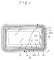
- Figs. 1 to 3 are views which illustrate a first embodiment of the present invention.
- a main container body 10 is formed in a substantially rectangular plate-like shape having a flange portion 13 at the top thereof.
- An outer peripheral 13B of this flange portion 13 is provided with a skirt portion 14 facing the bottom portion of the main container body 10, this skirt portion 14 serving as a portion to be bent.
- a cover 15 is welded to the above-described flange portion 13 so that an elongated sealing portion 16 is formed between the cover 15 and the flange portion 13.
- the main container body 10 is formed to be a multilayered structure which includes at least two layers consisting of an inner layer (a first layer) 11 confronting an inside portion 10B of the main container body 10 and an outer layer 12 (a second layer) which is so polymerized with this inner layer 11 as to be able to be separated from it.
- the peel strength between the inner layer 11 and the outer layer 12 is 300 to 2000g/15mm (tension speed 300mm/min to be identical hereinafter), preferably 400 to 1500g/15mm, this strength being required to be at least smaller than the sealing strength between the flange portion 13 and the cover 15.
- a notch 18 serving as an inner weakening line is formed at the position inner than a seal inner periphery 16A at a predetermined distance preferably T, while a cutting line 19 serving as an outer weakening line is formed outer than the seal outer periphery 16B. It is preferable that the depth of the notch 18 and the cutting line 19 reaches the boundary between the inner layer 11 and the outer layer 12. It is necessary for the structure to be arranged such that when the cover 15 is intended to be opened, the inner layer 11 and the outer layer 12 can be separated from each other from the cutting line 19 to the notch 18, causing the container to be opened.
- a hole portion 20 which serves as a non-sealing portion is formed, this hole portion 20 including a portion which corresponds to a portion of the cutting line 19, and the outer peripheral of this hole portion 20 with respect to the central portion of the container is arranged to be the seal outer peripheral 16B.
- This hole portion 20 is, as shown in Fig. 1, arranged such that the shape is formed to be circular and the number of it is one according to this embodiment.
- the position at which this hole portion is formed is not particularly limited and a plurality of holes may be formed there.
- the material for the main container body 10 is not limited particularly, it being exemplified by: polyolefin resin, polystyrene resin, polyamide resin, polyester resin, polycarbonate resin, a mixtures consisting of the above-described substances, a resin prepared by adding thermoplastic elastomer, various additives, or inorganic fillers in an amount of 5 to 70wt%, and metal foil.
- a suitable material needs to be selected from a combination of the layers each of which is formed by the above-described materials.
- the main container body 10 is formed to be a double-layered structure made of the above-described materials . However, it may be formed to be a multilayered structure consisting of triple or more layers manufactured by laminating layers made of the other material for the purpose of improving a gas-barrier performance or preventing any deformation occurred in the state of the completed container.
- the layer made of "the other material” is exemplified by a layer made of the material exhibiting an excellent gas barrier performance such as: a resin layer made of ethylene-vinyl alcohol copolymer, polyvinylidene chloride, nylon (polyamide), and polyethylene terephthalate; and a metal layer such as an aluminum evaporated layer or a layer made of aluminum or iron.
- the above-described layer made of the other material may be a single layer or a multilayered structure consisting of two or more layers. It may as well be a resin layer containing an inorganic filler in an amount of 10 to 80wt%.
- a suitable structure of the layers forming the main container body 10 is selected on the basis of the resin forming the sealant layer of the cover 15.
- the cover 15 is formed by a polyethylene sealant layers
- a structure is selected from the above-described group of combinations of the resin layers, this structure being arranged in such a manner that the high density polyethylene layer is employed to form the inner layer 11 of the main container body 10.
- the main container body 10 may be, if necessary, provided with the other layer such as a sealing layer, a heat resisting layer, or an oil-proof layer at the position inner than the innermost layer (inner layer 11) of the multilayered container if the characteristics of the present invention is satisfied such that a peeling layer is provided inside of the multilayered container.
- the thus-structured main container body 10 can be obtained by means of vacuum molding-compression molding, drawing, multilayer injection molding, multilayer injection blow molding, or multi layer blow molding, by using the above-described combination of resin, the laminate resin of the thus-obtained co-excluded multilayered sheet or resin sheet or film and the metal laminate. Alternatively, it can be obtained by heat forming a multilayered film on the inside of the main container body 10 made of paper or the like.
- the laminate working method is exemplified by extrusion laminating, hot melt laminating, dry laminating, and an wet laminating.
- a multilayered material having a suitable peel strength can be obtained by the above-described laminating in a pressure sensitive agent or an adhesive agent is used.
- cover 15 is structured to be a single-layered film, it is not limited as described above. It is not limited to this description. For example, it may be structured to be a multilayered film consisting of two or more layers.
- a structure is prefered which comprises: a base formed by a plastic single layered film, multilayered film, paper, aluminum foil, or a material manufactured by combining the above-described materials; and a sealant layer made of resin which can be readily heat sealed to the innermost layer (inner layer 11) of the main container body 10 such as polyethylene, polypropylene, ethylene- ⁇ -olefin copolymer, ethylenevinyl acetate copolymer, and the like.
- the container of the type described above is manufactured as follows: first the multilayered sheet is heated, and the above-described main container body 10 is formed from the thus-heated multilayered sheet by vacuum molding or compression molding. Then, the above-described notch 18 and the cutting line 19 are formed in prior to or after enclosing the content in the main container body 10.
- the notch 18 and the cutting line 19 can be formed by a physical method using a notching blade or cutting edge, a heating method such as heating ray melting (impulse) or melting in which a hot blade is used, a mechanically oscillating method by using ultrasonic wave, or an inner heating method by using high frequency. As described above, the depth of the formed notch 18 and the cutting line 19 needs to reach the inner layer 11 if it cannot reach the outer layer 12. It is reached the outer layer 12, the inner layer 11 can be assuredly separated from the outer layer 12.
- the flange portion 13 of the main container body 10 and the cover 15 are welded for sealing.
- a proper means such as heat sealing or ultrasonic sealing or the like can be employed.
- the flange portion 13 and the cover 15 are together punched such that the outer peripheral of the sealing portion 16 overlaps, and then the hole portion 20 is formed.
- this outer peripheral 16B of the sealing portion needs to overlap the hole portion 20. It is not of critical that the outer peripheral of the sealing portion 16 meets the cutting line 19.
- the hole portion 20 is formed in both the flange portion 13 and the cover 15 while corresponding to the cutting line 19 and the cover 15 is not welded, for sealing, to the flange portion 13 in this hole portion 20, the inner end of this hole portion 20 and the seal outer end 16B meet each other if the seal outer periphery 16B overlaps the hole portion 20. Therefore, when the container is intended to be opened, it can be readily opened by pulling the cover 15 at the end portion thereof towards the central portion of the container since the peeling of the layers of the flange portion 13 starts at the hole portion 20 which meets the seal outer periphery 16B.
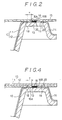
- a container according to a second embodiment of the present invention is structured as shown in Fig. 4, such that: the case 15 is formed to comprise the above-described inner layer 11 and the outer layer 12; the above-described notch 18 is formed inner than the sealing portion 16 of the cover 15 and the above-described cutting line 19 is formed outer than the sealing portion 16; and the hole portion 20 which serves as the non-sealing portion is formed at the position which corresponds to a portion of this cutting line 19. Furthermore, according to the second embodiment, the main container body 10 is not provided with the notch, the cutting line and the hole portion. In addition, the material for the main container body 10 is arranged to be the same resin as that for the inner layer 12 of the case 15 as to be tight-sealed to the latter.
- This main container body 10 may be formed, as shown in Fig. 4, to be a multilayered structure or a single layered structure. The other factors according to the second embodiment except for the structure above are the same as those according to the first embodiment.
- the container according to the second embodiment is manufactured as follows: the above-described notch 18, the cutting line 19, and the hole portion 20 are formed in the case 15; and this cover 15 is welded to the flange portion 13 of the main container body 10 in which the contents are enclosed for sealing. Also in this case, it needs for the seal outer periphery 16B to overlap the hole portion 20, but does not need to be positioned along the cutting line 19.
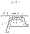
- a third embodiment of the present invention is structured as shown in Fig. 5 such that the hole portion 20 serving as the non-sealing portion is also formed in the cover 15 at the position thereof which includes a portion which corresponds to a portion of the above-described cutting line 19.
- the other structure is the same as that of the second embodiment.
- the container according to the third embodiment is structured as follows: the above-described notch 18 and the cutting line 19 are formed in the cover 15; this cover 15 is welded, for sealing, to the flange portion 13 of the main container body 10 in which the contents are enclosed; and the flange portion 13 and the cover 15 are together punched such that the outer periphery of the seal 16 overlaps before forming the hole portion 20. Also in this case, it needs for the seal outer periphery 16B to overlap the hole portion 20, but does not need to be positioned along the cutting line 19. According also to this third embodiment, a similar effect to that obtained-in the first and second embodiment can be obtained.
- the shape of the hole portion 20 serving as the non-sealing portion is formed to be circular, the present invention is not limited to this description.
- it may, as shown in Fig. 6(A), be a circular arc-like shape and the like.
- a structure may be employed arranged such that the hole portion 20 may be formed only in the flange portion 13 of the main container body 10.
- the bent portion formed in the flange portion 13 of the main container body 10 is arranged to be the skirt portion 14, the bent portion according to the present invention is not limited to this.
- it may be formed to be a shape of rib or a curl.
- it may be structured such that tabs 17A are extended over the ribs 17 formed in the flange portion 13.
- the sealing portion 16 when the sealing portion 16 is formed by heat sealing, a structure may be employed arranged such that the non-sealing portion is, as shown in Figs. 8 to 10, formed by a non-heat adhesive resin layer 21 or a heat-resisting label (omitted from illustration) made of an aluminum foil, paper, or the like is applied to the flange portion 13 in the outside portion including the above-described cutting line 19.
- the non-sealing portion may be formed by using both the above-described hole portion 20 and the non-heat adhesive resin layer 21.
- This non-heat adhesive layer 21 comprises a high melting point thermoplastic resin layer or a thermosetting resin layer applied to or printed on the surface of the flange portion 13 as to have the thickness of 1 to 5»m.
- This thermosetting resin is exemplified by: polyamide, polyester, polyamide-cellulose nitrate copolymer, cellulose nitrate-silicon resin copolymer, silicon resin, urethane resin, and aminoalkyd resin.
- the container shown in Figs. 8 and 9 is arranged such that the hole portion 20 is formed in the cover 15, while the container shown in Fig. 10 is arranged such that the hole portion 20 is formed in the cover 15 and the flange portion 13.
- the cover 15 can be readily separated from the inner end of the hole portion 20. Furthermore, even if the seal outer periphery 16B passed outward, as designated by an arrow Q, the cutting line 19 and the hole portion 20, the cover 15 can be readily separated at the cutting line 19 since the portion to which the non-heat adhesive resin layer 21 is not applied is not heat sealed.
- a structure may be employed such that the same comprises a recessed portion (omitted from illustration).
- This recessed portion can be formed by an edge of a sealing member when the cover 15 is welded to the flange portion 13 for sealing by using this sealing member.
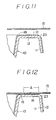
- FIG. 11 A forth embodiment of the present invention is shown in Fig. 11.
- This embodiment is characterized in that the outer corners of the flange portion 13 are cut and a boundary surface 23 of the inner layer 11 and the outer layer 12 which are positioned in contact with each other is allowed to appear.
- any method may be employed if the boundary surface 23 is allowed to appear for the purpose of causing the separation between the inner layer 11 and the outer layer 12 which is positioned in contact with the former layer to start.
- the outer corners of the flange portion 13 are formed by grinding, cutting in, cutting, melting on their periphery thereof.
- the container having the outer corners in the flange portion 13 can be molded by a special method.
- boundary surface 23 is allowed to appear is the most preferable method for the separation to start at this linear portion.
- another structure may be employed, for example, which is arranged such that it is allowed to appear partially if separation can start and the effect of the present invention is substantially achieved.
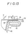
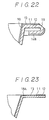
- Fig. 12 is a partial cross-sectional view which illustrates a state where the cover 15 is heat sealed to the main container body 10 according to the above-described fourth embodiment.
- This heat seal portion 16 is formed in a region A.
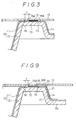
- Fig. 13 is a partial cross-sectional view which illustrates a portion in the vicinity of the flange portion 13 in the case where the cover 15 is heat sealed to the main curled-container body 10 according to another example of the fourth embodiment.
- the notch 18 is formed in the inner layer 11 at the inner wall of the main container body 10.
- This notch 18 may be, in the form of a circle, triangle, rectangular or the like, disposed all round of the flange portion 13 in the vicinity of the inner edge of this flange portion 13. Alternately, it may be provided partially with a portion remained. In the case where the cover 15 is separated with a portion thereof remained, it needs for the structure to be arranged in such a manner that any cutting is not provided in this portion. It is preferable that this heat sealing portion 16 is provided in the region designated by the symbol A shown in Fig. 13. The separation can be conducted if the same were provided in the region C. However, in the region B, the separation cannot be performed.
- length T from the inner end of the heat sealed portion to the notch is 0.5mm to 10mm in general, preferably 1.5mm to 5mm. If it is difficult to make the T to be within the above-described region when the heat sealing is performed, it is preferable that a slanted surface is provided in the inner surface of the flange portion as to make it a non-sealing region to be provided with a cutting.
- the non-sealing portion may be formed in a stepped shape, or a portion which cannot be fused by heat may be provided in the inner layer of the main container body so as to be a non-sealing region.
- the shape of the main body 10 of the multilayered container according to the present invention is not limited specifically. It is preferable that it is formed to be of circular in general, and a polygon such as a rectangular can be employed. Thus, the cover is angularly heat sealed along the flange portion of the shape described above.
- the shape may be arranged to be in the form of a cup-like shape or a tray-like shape. The notching of the outer periphery of the flange portion 13 of the circular shape of the main body of the multilayered container and the notching of the inner end portion can be readily performed by rotating at least either the container or the notching tool.
- the thus-obtained container was able to be separated from the outer end of the sealed portion of the flange portion between the layers of the container similarly to the separation realized in the flat flange provided container. Furthermore, the container stably displayed a peel strength of 1200g/15mm and clear separation surface.
- the main container body 10 is formed in the cylindrical shape, and the flange 13 to be welded for sealing to the cover 15 is formed all around in a circular opening 10A.
- the outer periphery 13B of this flange 13 is formed with a rib 14A serving as the bent portion is so forward as to face the bottom surface of the container.
- This main container body 10 is formed in a multilayered structure consisting of at least two layers stacked to each other in such a manner that the inner layer 11 can be separated from the outer layer 12.
- the peel strength between the inner layer 11 and the outer layer 12 is arranged to be substantially the same as that realized in the above-described embodiments.
- the notch 17 and the cutting line 18 are formed in the inner layer 17 disposed on both sides of the sealing portion 16 of the flange portion 11.
- the material, the combination of the layers and the like in the main container body 10 are the same as the above-described embodiments.
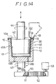
- a notching apparatus 30 comprises: holding means 40 for holding the main container body 10; rotating means 50 for rotating this holding means 40 relative to the center of the opening 10A in the container; first and second notching blades 61 and 62 for forming the above-described cut 17 and the cutting line 18 in the main container body 10.
- the above-described holding means 40 comprises: a container retainer 41 having a recessed portion 41A in which the main container body 10 is received; and a pressing member 42 for pressing the inner surface of the main container body 10 received in the above-described container retainer 41.
- the above-described container retainer 41 and the pressing member 42 are rotatably supported by rotational shafts 43 and 44 fastened coaxially.
- the pressing member 42 is arranged to be able to move forward and retracted in the axial direction. When this pressing member 42 is retracted, the main container body 10 is arranged to be transported to and drawn out from the container retainer 41 by means (omitted from illustration).
- an air outlet hole 41B is formed in the bottom portion of the container retainer 41 so that the main container body 10 can be smoothly transported to and drawn out from the container retainer 41. Furthermore, by blowing out of air through the air outlet hole 41B, the main container body 10 can be taken out from the container retainer 41.
- the above-described rotational means 50 comprises: a gear 51 connected to the container retainer 41 with a rotational shaft 43; and a motor 53 with a gear for rotating the gear 51 by using a timing belt 52.
- This motor 53 is arranged such that it intermittently rotates and stops so that when the same is being rotated, the cut is formed by the rotation of the container retainer 41 at the position which corresponds to at least the portion of the main container body 10 and the cover 15 in which the sealing therebetween is opened.
- the cut may be formed with a part thereof remained intact as an alternative to forming it all around.
- the above-described first notching blade 61 is disposed in such a manner that the front end portion thereof can be brought into contact with the position at which the cut 19 is formed, for example, the same can be brought into contact with the outer periphery 13B of the flange 13.
- the notching blade 62 is disposed in such a manner that the front end portion thereof can be brought into contact with the position at which the cut 18 is formed, for example, the same can be brought into contact with the inner periphery 13A of the flange 13.
- These notching blades 61 and 62 are arranged to move forward and retract by a means (omitted from illustration) so that the front end thereof can reach the inner layer 11 of the main container body 10 when the same moves forward.
- notching blades 61 and 62 are retracted, they are arranged to retract diagonally above the container retainer 41 as shown in Fig. 14 so as not to interrupt the transportation and drawing out of the main container body 10.
- These notching blades 61 and 62 are secured so as not to be moved due to the contact with the main container body 10 when they are moved forward so that the above-described cuts 18 and 19 are assuredly formed in the main container body 10.
- These notching blades 61 and 62 may be, if necessary, heated as to readily form the cuts 18 and 19.
- the shape of these notching blades 61 and 62 may be formed in any shape which can form the cut such as in a V-shape having a cut at the end thereof.
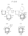
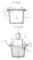
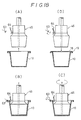
- FIG. 15 A method of notching the main container body 10 by using the apparatus which is thus-structured will be described with reference to Fig. 15.
- the rotational means is omitted from illustration and the main container body 10 is illustrated to be a single-layered body for making the description simple.
- the pressing member 42 and the notching blades 61 and 62 are respectively at the retracted positions, the pressing member 42 is moved forward after the main container body 10 in which the cuts have not been formed as yet has been received by the recessed portion 41A in the container retainer 41 so that the main container body 10 with the container retainer 41 are held.
- the notching blades 61 and 62 are moved forward, and simultaneously, the rotational means 50 (see Fig. 1) is rotated as shown in Fig. 15C as to rotate the container retainer 41 by a predetermined angular extent, for example, at least one rotation.
- the cuts 18 and 19 are simultaneously formed in the main container body 10.
- the pressing member 42 is simply and rotatably supported by the rotational shaft 44, the same with the container retainer 41 holds the main container body 10 strongly enough. Therefore, it rotates with the container retainer 41. Furthermore, as shown in Fig. 15D, the pressing member 42 is retracted after the notching blades 61 and 62 have been retracted, and the main container body 10 in which the cuts 18 and 19 have been formed is drawn out.
- the cuts 18 and 19 can be assuredly formed in the flange portion 13 regardless of the non-uniform thickness of the flange portion 13, in particular, regardless of the non-uniform thickness of the outer layer 12 even if the flange portion 13 has the rib 14A thereon. Furthermore, by using a proper type of blades as the notching blades 61 and 62, the cuts 18 and 19 can be formed regardless of the material for the inner layer 11, that is even if the material were high melting point or high strength resin, or metal such as aluminum, the cuts 18 and 19 can be formed.
- the above-described cuts 18 and 19 can be formed at any desired positions in the flange portion 13.
- the width to be sealed does not need to be strictly set when the cover 15 is welded for sealing on the flange portion 13 of the main container body 10.
- the sealing work for the main container body 10 can be readily conducted.
- expensive annular notching blades can be replaced by relatively cheap notching blades 61 and 62 above, the cost required to form the cuts can be reduced.
- This embodiment is arranged such that the structure of the means for holding the main container body 10 and the notching blade are different from those of the above-described embodiments.
- the structure of the main container body and the rotational means 50 are the same as those of the above-described embodiments.
- the rotational means 50 is omitted from illustration in Figs. 17 and 18.
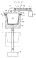
- the holding means comprises a vacuum adsorption means 45 for adsorbing, by its negative pressure, the inside of the main container body 10 which has been brought adjacent by a lifting means (omitted from illustration).
- This vacuum adsorption means 45 is formed in a substantially circular cylinder having a recessed portion at the base portion thereof, this vacuum adsorption means 45 comprising, in the shaft thereof, an inlet/outlet hole 45A which is connected to a pressure reducing system and/or high pressure system (omitted from illustration).
- This vacuum adsorption (blowing-out attaching/detaching) means 45 is arranged to be rotated with connected to the above-described rotational means 50 (see Fig. 14) and the main container body 10 thereby held.
- the notching blade comprises: a rotary type notching blade 63 for forming the cut 19 (see Fig. 19) by diagonally notching the outer periphery 13B of the flange portion 13; and a notching blade 64 for forming the above-described cut 18 in the inner periphery 13A of the flange portion 13.
- the above-described notching blade 63 is arranged to be capable of moving forward and retracting so that when the same is moved forward, the cut 19 can reach the inner wall 11 of the main container body 10.
- the above-described notching blade 64 formed in a hook shape and capable of rotating relative to the base end portion thereof, the notching edge formed at the front end thereof being always abutted under a predetermined urging force against the inner periphery 13A of the flange portion 13 by means of a spring (omitted from illustration), while the same being capable of retracting against the above-described urging force when this notching edge does not form the cut. Thanks to the thus-formed method, the cut can be formed in the inner layer 11 by means of a press molding, causing an advantage in that the cuts exhibiting a predetermined depth can be formed even if the portion of the main container body 10 at which the cut is formed were not of uniform.
- FIG. 18 A method of forming the cut in the main container body 10 by using the notching apparatus according to this embodiment and structured as described above will be described with reference to Fig. 18.
- the main container body 10 is formed in a single-layered structure for the purpose of making the description simple.
- the notching blades 63 and 64 are positioned at their retracted positions, the main container body 10 in which the cuts have not as yet been formed is brought to a position adjacent to the vacuum adsorption means 45 by the lifting means (omitted from illustration). Then, this vacuum adsorption means 45 is actuated so that the main container body 10 is held. As shown in Fig. 18B, the notching blades 63 and 64 are then moved forward, and the rotational means 50 (see Fig. 14) is rotated as shown in Fig. 18C for the purpose of rotating the vacuum adsorption means 45 by a predetermined angular extent, in general one rotation.
- the cut 18A designated by an imaginary line shown in Fig. 19 can be formed by adjusting the relative positions of the notching blades 63 and 64.
- the holding means is arranged to comprise the vacuum adsorption means 45, the number of necessary parts can be reduced with respect to the above-described embodiments; since the notching blade 63 is arranged to be of a rotary type, the cut 19 can be smoothly and assuredly formed.
- This embodiment is structured such that the notching apparatus 30 is included in the container printing apparatus and characterized in that the structure of the rotational means and the position of the notching blade are different from the those of the above-described embodiments.
- the structures of the holding means and the container are the same.
- the notching blade is omitted from illustration.
- the vacuum adsorption means 45 serving as the holding means according to this embodiment is rotatably fitted to the front end of the rod-like shaped support member 71A formed radially over the rotational center of the container floating means 71.
- the notching blades 61 to 64 according to this embodiment are formed in similar shape as that of the above-described embodiments (see Figs. 14, 15, 17, and 18), and is fastened to the above-described support member 71A.
- the notching blades are, similarly to those in the above-described embodiments, arranged such that the front ends thereof can reach the inner layer 11.
- the rotary means comprises a printing roll 55 for printing the outer surface of the main container body 10 held by the above-described vacuum adsorption means 45.
- this printing roll 55 is rotated, the main container body 10 is also rotated due to the friction with the printing roll 55.
- the rotation of this main container body 10 may be arranged to be performed in the other zones such as the dry portion as an alternative to the printing portion.
- the cut can be, in general, formed in the main container body 10 during the printing process. That is, the main container body 10 held by the vacuum adsorption means 45 is also rotated in correspondence with the rotation of the printing roll 55. During this rotation, the cuts can be formed in the main container body 10 by the notching blades fastened to the support member 71A.
- the flange portion 13 formed in the main container body 10 to be formed with the cuts is provided with a curling 14B serving as the bent portion in the outer periphery 13B thereof.
- the holding means comprises a recessed portion 46A for accommodating the main container body 10, and this holding means is arranged to be the vacuum adsorption means 46 for adsorbing the main container body 10 by its negative pressure.
- This vacuum adsorption means 46 is arranged to be capable of moving forward and retracting by a cylinder 47. When the vacuum adsorption means 46 is moved forward, it adsorbs the main container body 10, while it releases its pressure as to cause the main container body to be taken out or taken in by a means (omitted from illustration) when it is retracted.
- the notching blade 65 has its notching edge at the side edge of the bent front end portion thereof so that the cut 19 (see Fig. 22) is formed diagonally in the outer periphery of the flange portion 13.
- the notching blade 66 is arranged to have the similar shape as that of the above-described embodiments so that the cut 18 is formed.
- These notching blades 65 and 66 are fastened to the front end of a plate member 67 having the base end thereof which is connected, with the rotational shaft 44, to the above-described rotational means 50 according to the above-described embodiments.
- the above-described plate. member 67 is arranged to be of elastic for the purpose of making the above-described notching blades 65 and 66 against the main container body 10 with a predetermined urging force when the vacuum adsorption means 46 is moved forward.
- the vacuum adsorption means 46 is moved forward. Then, the notching blades 65 and 66 are rotated by the rotational means. As a result, the cuts 18 and 19 (see Fig. 22) are formed. After the above-described cuts 18 and 19 have been formed, the vacuum adsorption means 46 is retracted and the main container body 10 is transported.
- the cuts 18 and 19 can be assuredly formed in the flange portion 13 having the curling 14B of the main container body 10.
- the vacuum adsorption means 46 does not need to be rotated, the structure of this vacuum adsorption means 46 can be simplified.
- the shape of the flange portion 13 to be applied to the present invention may be, as shown in Fig. 23, formed flat as an alternative to the shape having the rib or the like.
- the number of the same may be, as shown in Fig. 23, one or three or more.
- the two cuts may be formed by one notching blade.
- the cuts may be formed in the main container body 10 by moving both the holding means 40 (vacuum adsorption means 45 and 46) and the notching blade.
- the above-described rotational means formed by the gears, the timing belt and the motor according to the above-described embodiments may be formed any means comprising a pulley, a belt, and a motor, or means comprising a plurality of gears and a motor if the same can rotate at least either of the holding means and the notching blade.
- a container exhibiting an excellent sealing performance and capable of being readily opened can be provided.
- an effect that the cuts can be formed at any positions in the flange can be obtained.
- the cuts can be readily formed in the inner wall on the inside of the flange portion of the container, the overall portion of the flange surface can be tightly sealed when the cover of the container is tightly sealed to the main container body as well as the effect of forming the cuts. Consequently, a great advantage can be obtained in the field of the packing.
Landscapes
- Engineering & Computer Science (AREA)
- Mechanical Engineering (AREA)
- Packages (AREA)
- Auxiliary Devices For And Details Of Packaging Control (AREA)
- Perforating, Stamping-Out Or Severing By Means Other Than Cutting (AREA)
- Paper (AREA)
- Glass Compositions (AREA)
- Adornments (AREA)
Claims (11)
- Behälter aus einem Behälter-Hauptkörper (10) mit einem umgebogenen Randbereich (13) und einem zum Versiegeln mit dem umgebogenen Rand verschweißten Deckel (15), welcher umfaßt:
eine innere Schicht (11), die das Innere des Behälter-Hauptkörpers auskleidet und eine äußere Schicht (12), die so an die innere Schicht laminiert ist, daß sie sich von der inneren Schicht ablösen kann, wobei die Schichten in mindestens dem Behälter-Hauptkörper (10) oder dem Deckel (15) vorhanden sind, wenn der Behälter-Hauptkörper und der Deckel geformt werden, wobei die Haftfestigkeit zwischen der inneren Schicht und der äußeren Schicht so eingestellt ist, daß sie kleiner ist als die zwischen dem umgebogenen Randbereich (13) des Behälter-Hauptkörpers (10) und dem Deckel (15),
eine innere Sollbruchlinie (18), die in dem umgebogenen Randbereich (13), der die innere und die äußere Schicht enthält oder an der Überlappungsstelle von Deckel und umgebogenem Randbereich (13) in dem Deckel, der die innere und die äußere Schicht enthält, an einer bezüglich des Versiegelungsbereichs (16) innen liegenden Stelle ausgebildet ist,
eine äußere Sollbruchlinie (19), die an einer bezüglich des Versiegelungsbereichs (16) außen liegenden Stelle in dem umgebogenen Randbereich ausgebildet ist, und
mindestens einen Nicht-Siegelungsbereich (20), welcher in dem Deckel und/oder dem umgebogenen Randbereich an der Stelle ausgebildet ist, die mit dem Bereich zusammenfällt, der einem Teil der äußeren Sollbruchlinie entspricht. - Behälter nach Anspruch 1, worin der Nicht-Siegelungsbereich einen Hohlraum (20) darstellt.
- Behälter nach Anspruch 1, worin der Nicht-Siegelungsbereich durch eine nicht heißsiegelbare Harzschicht gebildet ist.
- Behälter nach Anspruch 1, worin in dem umgebogenen Randbereich (13) des Behälter-Hauptkörpers (10) ein gebogener Teil (14) ausgebildet ist.
- Behälter nach Anspruch 1, worin der Behälter-Hauptkörper (10) an dessen umgebogenem Randbereich (13) mit dem Deckel (15) zum Versiegeln verschweißt ist, wobei der Behälter-Hauptkörper umfaßt:
eine innere Schicht (11), die das Innere des Behälter-Hauptkörpers auskleidet und eine äußere Schicht (12), die so an die innere Schicht laminiert ist, daß sie sich von der inneren Schicht ablösen kann, wobei die Haftfestigkeit zwischen der inneren Schicht (11) und der äußeren Schicht (12) so eingestellt ist, daß sie kleiner ist als die zwischen dem umgebogenen Randbereich (13) und dem Deckel (15),
eine innere Sollbruchlinie (18), die im inneren Bereich des umgebogenen Randes ausgebildet ist,
eine äußere Sollbruchlinie, die an einer bezüglich der inneren Sollbruchlinie außerhalb liegenden Stelle ausgebildet ist, und
einen Nicht-Siegelungsbereich, der in dem umgebogenen Randbereich an einer Stelle ausgebildet ist, die einen Bereich umfaßt, der einem Teil der äußeren Sollbruchlinie entspricht. - Behälter nach Anspruch 1, welcher umfaßt :
eine Rippe oder einen eingerollten Bereich; und
einen ringförmigen Schnitt, der in der Nähe des inneren Umfangs des umgebogenen Randbereichs (13) eines mit einem umgebogenen Rand versehenen mehrschichtigen Behälters ausgebildet ist, wobei dessen innere Schicht (11) und eine Schicht (12), die mit der inneren Schicht in Kontakt ist, voneinander getrennt werden können, worin
an den Ecken des äußeren Umfangs des umgebogenen Randbereichs eine Grenzfläche zwischen einer innersten Schicht und einer Schicht, die mit der innersten Schicht in Kontakt ist, vorgesehen ist. - Behälter nach Anspruch 6, worin der umgebogene Randbereich (13) ringförmig ausgebildet ist.
- Verfahren zum Kerben eines Behälters nach einem der Ansprüche 1 bis 7, wobei der Behälter, der an seiner Öffnung einen umgebogenen Randbereich (13) hat, mit einem Kerbmesser geschnitten wird, welches darin besteht, daß
der Behälter und das Kerbmesser relativ zueinander in Umfangsrichtung um die Öffnung des Behälters bewegt werden, wobei der Behälter so ausgestaltet ist, daß er eine innere Schicht (11), die das Innere des Behälters auskleidet, und eine äußere Schicht (12), welche die innere Schicht überdeckt, enthält und wobei die innere Schicht von der äußeren Schicht getrennt werden kann, wodurch in der inneren Schicht des Behälters Schnitte ausgebildet werden. - Verfahren zum Kerben eines Behälters nach Anspruch 8, wobei
der äußere Umfang des Behälters einschließlich eines gebogenen Teils, der in dem äußeren Umfang des umgebogenen Randes (13) des Basisteils des Behälters gebildet ist,
der innere Umfang des umgebogenen Randes, und
das Kerbmesser relativ zueinander in Umfangsrichtung um die Öffnung des Behälters herum bewegt werden. - Vorrichtung zum Kerben eines Behälters nach einem der Ansprüche 1 bis 7, welche umfaßt:
eine Haltevorrichtung (40) zum Festhalten eines mit einer ringförmigen Öffnung, in der ein umgebogener Rand ausgebildet ist, versehenen Behälters, der eine innere Schicht (11), die das Innere des Behälters auskleidet, und eine äußere Schicht (12), die die innere Schicht überdeckt, enthält, wobei die innere Schicht von der äußeren Schicht getrennt werden kann,
ein Kerbmesser (61, 62) zum Ausbilden eines Schnitts in der inneren Schicht des Behälters und
eine Drehvorrichtung (50) zum Drehen von mindestens der Haltevorrichtung (40) und des Kerbmessers relativ zu dem Zentrum der Öffnung (10A) des Behälters, um den Behälter und das Kerbmesser relativ zueinander in Umfangsrichtung um die Öffnung des Behälters herum zu bewegen. - Vorrichtung nach Anspruch 10, worin die Haltevorrichtung (40) eine Vakuum-Ansaugeinrichtung umfaßt, die den Behälter mittels Unterdruck festhalten kann.
Applications Claiming Priority (4)
| Application Number | Priority Date | Filing Date | Title |
|---|---|---|---|
| JP165580/88 | 1988-07-01 | ||
| JP63165580A JP2552176B2 (ja) | 1988-07-01 | 1988-07-01 | 容 器 |
| JP245562/88 | 1988-09-28 | ||
| JP63245562A JPH0298560A (ja) | 1988-09-28 | 1988-09-28 | 容器 |
Publications (3)
| Publication Number | Publication Date |
|---|---|
| EP0349009A2 EP0349009A2 (de) | 1990-01-03 |
| EP0349009A3 EP0349009A3 (en) | 1990-11-22 |
| EP0349009B1 true EP0349009B1 (de) | 1995-05-03 |
Family
ID=26490263
Family Applications (1)
| Application Number | Title | Priority Date | Filing Date |
|---|---|---|---|
| EP89112010A Expired - Lifetime EP0349009B1 (de) | 1988-07-01 | 1989-06-30 | Behälter, Schneidverfahren und Vorrichtung zur seiner Herstellung |
Country Status (9)
| Country | Link |
|---|---|
| US (1) | US5141126A (de) |
| EP (1) | EP0349009B1 (de) |
| KR (1) | KR930008921B1 (de) |
| AT (1) | ATE122016T1 (de) |
| AU (3) | AU628352B2 (de) |
| BR (1) | BR8903244A (de) |
| CA (1) | CA1334524C (de) |
| DE (1) | DE68922441T2 (de) |
| NZ (1) | NZ229781A (de) |
Families Citing this family (17)
| Publication number | Priority date | Publication date | Assignee | Title |
|---|---|---|---|---|
| JP2724355B2 (ja) * | 1990-06-15 | 1998-03-09 | 出光石油化学株式会社 | 易開封性容器及びその製造方法 |
| US5447236A (en) * | 1994-03-22 | 1995-09-05 | The Pillsbury Company | Multiple compartment package |
| EP0788979B1 (de) * | 1995-09-13 | 2004-12-01 | Dai Nippon Printing Co., Ltd. | Verpackung |
| USH1857H (en) * | 1995-12-21 | 2000-09-05 | Eastman Chemical Company | Method for reducing peel defects in adhesive bonded plastics |
| FR2759975B1 (fr) * | 1997-02-25 | 1999-07-09 | Michel Bras | Procede d'assemblage de deux contenants de deux substances destinees a etre melangees puis consommees |
| JP4133436B2 (ja) * | 2003-02-26 | 2008-08-13 | 出光ユニテック株式会社 | 易開封性包装体および易開封性包装体の製造方法 |
| AT500536B8 (de) * | 2004-02-02 | 2007-02-15 | Teich Ag | Zweilagiges, deckelförmig ausgestanztes verschlusselement |
| US20090114650A1 (en) * | 2007-11-01 | 2009-05-07 | Houston Jr Michael Roderick | Compartment container |
| US20110174819A1 (en) * | 2010-01-18 | 2011-07-21 | John Murphy | Tamper evident container |
| JP2015093703A (ja) * | 2013-11-12 | 2015-05-18 | 出光ユニテック株式会社 | 容器の製造方法および容器 |
| DE102015205221A1 (de) * | 2015-03-23 | 2016-09-29 | Multivac Sepp Haggenmüller Se & Co. Kg | Tiefziehverpackungsmaschine, Verfahren und Verpackung |
| JP6530997B2 (ja) * | 2015-07-31 | 2019-06-12 | 昭和電工パッケージング株式会社 | ノッチ形成刃 |
| USD804300S1 (en) | 2015-11-12 | 2017-12-05 | The J. M. Smucker Company | Container |
| US11203189B2 (en) | 2016-06-15 | 2021-12-21 | Bemis Company, Inc. | Heat-seal lid with non-heat sealing layer and hydrophobic overcoat |
| US12103283B2 (en) * | 2017-11-21 | 2024-10-01 | Smilesys S.P.A. | Closure member for a food container and method of manufacturing of said closure member |
| DK3747786T3 (da) * | 2019-06-04 | 2022-07-11 | Silver Plastics Gmbh & Co Kg | Emballagebakke med profileret tætningsrand |
| EP3766684B1 (de) * | 2019-07-16 | 2022-11-09 | Constantia Teich GmbH | Verbundmaterial zur herstellung von platinen und daraus hergestellte platinen |
Family Cites Families (11)
| Publication number | Priority date | Publication date | Assignee | Title |
|---|---|---|---|---|
| US4044941A (en) * | 1976-04-12 | 1977-08-30 | Knudsen David S | Container closed by a membrane type seal |
| SE423218B (sv) * | 1977-11-17 | 1982-04-26 | Haustrup Plastic As | Anordning vid originalforsluten och aterforslutbar behallare |
| US4280653A (en) * | 1979-10-01 | 1981-07-28 | Boise Cascade Corporation | Composite container including a peelable membrane closure member, and method |
| FR2516052A1 (fr) * | 1981-11-06 | 1983-05-13 | Plastigord Plastiques Perigord | Boite a fermeture etanche formant conteneur pour produits divers |
| US4450614A (en) * | 1982-02-19 | 1984-05-29 | Microdot Inc. | Method of making a polytetrafluoroethylene hydrodynamic seal |
| CA1303522C (en) * | 1986-04-08 | 1992-06-16 | Takanori Suzuki | Easily-openable packaging container |
| KR910002152B1 (ko) * | 1986-09-30 | 1991-04-06 | 이데미쓰세끼유가가꾸 가부시끼가이샤 | 용이 개봉성 포장용기 및 그의 리드 |
| US4913307A (en) * | 1986-09-30 | 1990-04-03 | Idemitsu Petrochemical Co., Ltd. | Easily openable packaging container and method for producing the same |
| US4693390A (en) * | 1986-10-15 | 1987-09-15 | Continental Can Company, Inc. | Lid for a plastic container |
| US4865217A (en) * | 1987-08-31 | 1989-09-12 | Sumitomo Bakelite Company, Limited | Easily openable sealed container |
| NZ226028A (en) * | 1987-09-09 | 1990-06-26 | Idemitsu Petrochemical Co | Hermetically sealed package which can be resealed after opening |
-
1989
- 1989-06-30 NZ NZ229781A patent/NZ229781A/en unknown
- 1989-06-30 CA CA000604625A patent/CA1334524C/en not_active Expired - Lifetime
- 1989-06-30 AU AU37258/89A patent/AU628352B2/en not_active Ceased
- 1989-06-30 DE DE68922441T patent/DE68922441T2/de not_active Expired - Fee Related
- 1989-06-30 AT AT89112010T patent/ATE122016T1/de not_active IP Right Cessation
- 1989-06-30 US US07/374,134 patent/US5141126A/en not_active Expired - Lifetime
- 1989-06-30 EP EP89112010A patent/EP0349009B1/de not_active Expired - Lifetime
- 1989-06-30 BR BR898903244A patent/BR8903244A/pt not_active IP Right Cessation
- 1989-07-01 KR KR1019890009365A patent/KR930008921B1/ko not_active Expired - Fee Related
-
1992
- 1992-12-07 AU AU29928/92A patent/AU660343B2/en not_active Ceased
- 1992-12-07 AU AU29927/92A patent/AU655341B2/en not_active Ceased
Also Published As
| Publication number | Publication date |
|---|---|
| NZ229781A (en) | 1992-03-26 |
| KR930008921B1 (ko) | 1993-09-17 |
| DE68922441T2 (de) | 1996-02-01 |
| BR8903244A (pt) | 1990-02-13 |
| AU655341B2 (en) | 1994-12-15 |
| AU628352B2 (en) | 1992-09-17 |
| ATE122016T1 (de) | 1995-05-15 |
| AU2992792A (en) | 1993-02-11 |
| EP0349009A3 (en) | 1990-11-22 |
| KR900001579A (ko) | 1990-02-27 |
| DE68922441D1 (de) | 1995-06-08 |
| AU3725889A (en) | 1990-01-04 |
| AU2992892A (en) | 1993-02-11 |
| EP0349009A2 (de) | 1990-01-03 |
| AU660343B2 (en) | 1995-06-22 |
| US5141126A (en) | 1992-08-25 |
| CA1334524C (en) | 1995-02-21 |
Similar Documents
| Publication | Publication Date | Title |
|---|---|---|
| EP0349009B1 (de) | Behälter, Schneidverfahren und Vorrichtung zur seiner Herstellung | |
| EP0461640B1 (de) | Leicht zu öffnender Behälter und Verfahren zu seiner Herstellung | |
| EP0282773B1 (de) | Mehrlagige Platte zur Herstellung eines mehrlagigen Behälters | |
| US5178293A (en) | Easily-openable packaging container | |
| EP1616811B1 (de) | Behälter, verpackungskörper und verfahren zur herstellung des behälters | |
| US20100172604A1 (en) | Reclosable Container with Resealable Flexible Cover and Method for Manufacturing the Same | |
| EP1526090A2 (de) | Behälter mit leicht abnehmbarer Membranabdeckung | |
| JP3208007B2 (ja) | 易開封性密封容器 | |
| JP2698486B2 (ja) | 密閉容器 | |
| JPH08295367A (ja) | 易開封性包装体およびその製造方法 | |
| NZ238978A (en) | Multi-layered container with weakening line and break in the first layer | |
| JP7324431B1 (ja) | 蓋材付き紙製容器、ブランク材及び紙製容器 | |
| JP4489515B2 (ja) | ミシン目 | |
| JP3546940B2 (ja) | 密封包装体 | |
| JP3126092B2 (ja) | 密封容器とその製造方法 | |
| JPH08151041A (ja) | 巻締容器 | |
| JP2630363B2 (ja) | 容器の切り欠き方法及びその切欠装置 | |
| JPH0539086Y2 (de) | ||
| JP2984464B2 (ja) | 易開封性密封容器 | |
| JP6088888B2 (ja) | 容器本体、容器、包装容器、シール方法、および、容器本体の製造方法 | |
| JPH0575636B2 (de) | ||
| JPH08198250A (ja) | 包装容器の開口構造及びその製造方法 |
Legal Events
| Date | Code | Title | Description |
|---|---|---|---|
| PUAI | Public reference made under article 153(3) epc to a published international application that has entered the european phase |
Free format text: ORIGINAL CODE: 0009012 |
|
| AK | Designated contracting states |
Kind code of ref document: A2 Designated state(s): AT BE CH DE FR GB IT LI NL SE |
|
| PUAL | Search report despatched |
Free format text: ORIGINAL CODE: 0009013 |
|
| AK | Designated contracting states |
Kind code of ref document: A3 Designated state(s): AT BE CH DE FR GB IT LI NL SE |
|
| 17P | Request for examination filed |
Effective date: 19901219 |
|
| 17Q | First examination report despatched |
Effective date: 19920825 |
|
| GRAA | (expected) grant |
Free format text: ORIGINAL CODE: 0009210 |
|
| ITF | It: translation for a ep patent filed | ||
| AK | Designated contracting states |
Kind code of ref document: B1 Designated state(s): AT BE CH DE FR GB IT LI NL SE |
|
| PG25 | Lapsed in a contracting state [announced via postgrant information from national office to epo] |
Ref country code: NL Free format text: LAPSE BECAUSE OF FAILURE TO SUBMIT A TRANSLATION OF THE DESCRIPTION OR TO PAY THE FEE WITHIN THE PRESCRIBED TIME-LIMIT Effective date: 19950503 Ref country code: LI Effective date: 19950503 Ref country code: CH Effective date: 19950503 Ref country code: BE Effective date: 19950503 Ref country code: AT Effective date: 19950503 |
|
| REF | Corresponds to: |
Ref document number: 122016 Country of ref document: AT Date of ref document: 19950515 Kind code of ref document: T |
|
| REF | Corresponds to: |
Ref document number: 68922441 Country of ref document: DE Date of ref document: 19950608 |
|
| ET | Fr: translation filed | ||
| PG25 | Lapsed in a contracting state [announced via postgrant information from national office to epo] |
Ref country code: SE Effective date: 19950803 |
|
| REG | Reference to a national code |
Ref country code: CH Ref legal event code: PL |
|
| NLV1 | Nl: lapsed or annulled due to failure to fulfill the requirements of art. 29p and 29m of the patents act | ||
| PLBE | No opposition filed within time limit |
Free format text: ORIGINAL CODE: 0009261 |
|
| STAA | Information on the status of an ep patent application or granted ep patent |
Free format text: STATUS: NO OPPOSITION FILED WITHIN TIME LIMIT |
|
| 26N | No opposition filed | ||
| REG | Reference to a national code |
Ref country code: GB Ref legal event code: IF02 |
|
| REG | Reference to a national code |
Ref country code: GB Ref legal event code: 732E |
|
| PGFP | Annual fee paid to national office [announced via postgrant information from national office to epo] |
Ref country code: FR Payment date: 20050608 Year of fee payment: 17 |
|
| PGFP | Annual fee paid to national office [announced via postgrant information from national office to epo] |
Ref country code: DE Payment date: 20050623 Year of fee payment: 17 |
|
| PGFP | Annual fee paid to national office [announced via postgrant information from national office to epo] |
Ref country code: GB Payment date: 20050629 Year of fee payment: 17 |
|
| REG | Reference to a national code |
Ref country code: FR Ref legal event code: TP |
|
| PG25 | Lapsed in a contracting state [announced via postgrant information from national office to epo] |
Ref country code: GB Free format text: LAPSE BECAUSE OF NON-PAYMENT OF DUE FEES Effective date: 20060630 |
|
| PGFP | Annual fee paid to national office [announced via postgrant information from national office to epo] |
Ref country code: IT Payment date: 20060630 Year of fee payment: 18 |
|
| PG25 | Lapsed in a contracting state [announced via postgrant information from national office to epo] |
Ref country code: DE Free format text: LAPSE BECAUSE OF NON-PAYMENT OF DUE FEES Effective date: 20070103 |
|
| GBPC | Gb: european patent ceased through non-payment of renewal fee |
Effective date: 20060630 |
|
| REG | Reference to a national code |
Ref country code: FR Ref legal event code: ST Effective date: 20070228 |
|
| PG25 | Lapsed in a contracting state [announced via postgrant information from national office to epo] |
Ref country code: FR Free format text: LAPSE BECAUSE OF NON-PAYMENT OF DUE FEES Effective date: 20060630 |
|
| PG25 | Lapsed in a contracting state [announced via postgrant information from national office to epo] |
Ref country code: IT Free format text: LAPSE BECAUSE OF NON-PAYMENT OF DUE FEES Effective date: 20070630 |