EP0348931B1 - Pompe turbomoléculaire - Google Patents
Pompe turbomoléculaire Download PDFInfo
- Publication number
- EP0348931B1 EP0348931B1 EP89111755A EP89111755A EP0348931B1 EP 0348931 B1 EP0348931 B1 EP 0348931B1 EP 89111755 A EP89111755 A EP 89111755A EP 89111755 A EP89111755 A EP 89111755A EP 0348931 B1 EP0348931 B1 EP 0348931B1
- Authority
- EP
- European Patent Office
- Prior art keywords
- piston
- bore
- rotor
- bearings
- stator
- Prior art date
- Legal status (The legal status is an assumption and is not a legal conclusion. Google has not performed a legal analysis and makes no representation as to the accuracy of the status listed.)
- Expired - Lifetime
Links
- 239000004519 grease Substances 0.000 claims abstract description 19
- 238000007789 sealing Methods 0.000 claims description 4
- 238000005461 lubrication Methods 0.000 description 12
- 238000012423 maintenance Methods 0.000 description 2
- 230000000737 periodic effect Effects 0.000 description 2
- 230000001419 dependent effect Effects 0.000 description 1
- 238000006073 displacement reaction Methods 0.000 description 1
- 230000002349 favourable effect Effects 0.000 description 1
- 238000003780 insertion Methods 0.000 description 1
- 230000037431 insertion Effects 0.000 description 1
Images

Classifications
-
- F—MECHANICAL ENGINEERING; LIGHTING; HEATING; WEAPONS; BLASTING
- F04—POSITIVE - DISPLACEMENT MACHINES FOR LIQUIDS; PUMPS FOR LIQUIDS OR ELASTIC FLUIDS
- F04D—NON-POSITIVE-DISPLACEMENT PUMPS
- F04D29/00—Details, component parts, or accessories
- F04D29/06—Lubrication
- F04D29/063—Lubrication specially adapted for elastic fluid pumps
-
- F—MECHANICAL ENGINEERING; LIGHTING; HEATING; WEAPONS; BLASTING
- F04—POSITIVE - DISPLACEMENT MACHINES FOR LIQUIDS; PUMPS FOR LIQUIDS OR ELASTIC FLUIDS
- F04D—NON-POSITIVE-DISPLACEMENT PUMPS
- F04D19/00—Axial-flow pumps
- F04D19/02—Multi-stage pumps
- F04D19/04—Multi-stage pumps specially adapted to the production of a high vacuum, e.g. molecular pumps
- F04D19/042—Turbomolecular vacuum pumps
Definitions
- the present invention relates to a turbomolecular pump.
- Grease-lubricated turbomolecular, vane, or Ga ⁇ de channel pumps should be closely monitored. Indeed, the maximum time interval between two consecutive lubrication depends on the operating temperature of the pump and the actual time of use. This manual maintenance operation requires vigilance on the part of the user, which is not always possible to obtain.
- This lubrication operation is carried out with the pump stopped and returned to atmospheric pressure. Lubrication is carried out after removing the inlet plugs, introducing the strictly necessary quantity of new grease using a syringe allowing this quantity to be dosed.
- the German document DE-A-2,853,742 describes a lubrication system for a turbomolecular vacuum pump.
- the system comprises in the central shaft of the pump a bore in which are provided grease reserve chambers from which radially leave channels leading to the ball bearings, directly on the ball cage and radially, the bearings not comprising inner ring.
- the internal raceway of the balls is directly produced on the shaft on which the bearings are mounted.
- a central piston makes it possible to push the grease from time to time. The end of this piston is threaded and the piston is pushed by rotating the piston using a screwdriver.
- the central shaft is rotary, in another, the central shaft is fixed carrying the stator of a drive motor, the rotor of which, integral with the pump rotor, is located around the stator of the engine.
- the present invention aims to overcome all these drawbacks and to allow automatic and metered lubrication of the pump during its operation.
- the invention thus relates to a turbomolecular pump comprising a rotor and a stator, the rotor being supported in the stator by bearings, the stator, in its part carrying said bearings, being pierced with a bore equipped with a delimiting piston with said bore of the chambers constituting grease reserves, at least one radial channel extending from each of these chambers, said piston comprising, on the side of its external end, means for allowing its insertion into said bore, characterized in that each channel ends in front of a threaded cylindrical seat, integral with the rotor and immediately adjacent to a rotor support bearing, supplying the grease axially to said bearing according to a circular crown, said piston being fitted with a seal located between the chambers and its outer end, said means allowing the piston to be pushed into the bore comprising a motor means started periodically.
- said rotor is integral with a rotor support shaft on which said bearings are mounted, said bore being drilled parallel to the axis of said shaft, said cylindrical threaded surfaces being located on said rotor support shaft.
- said stator is integral with a fixed central shaft on which are mounted said bearings and around which rotates said rotor, said bore being drilled in the axis of said fixed central shaft.
- said bore is tapped at its beginning and cooperates with the end, external side, of the piston carrying a threaded seat, a rotary drive motor being coupled with said piston.
- the periodic start-up of said motor means is carried out by a command as a function of the effective time of operation of the pump.
- the control can also take into account the temperature of the pump and also possibly the internal pressure of the machine at the bearings.
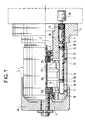
- FIG. 1 represents a part 1 of a stator of a turbomolecular pump of the Ga ⁇ de channel type whose rotor 40, partially shown, is in the shape of a bell which covers the represented part of the stator.
- the rotor is integral with a rotor support shaft 30 which penetrates into the central bore 2 of part 1 of the stator, and rests in this part 1 of stator on two bearings, for example ball bearings 3 and 4.
- the stator comprises a second part, not shown, which covers the rotor 40 and comes to rest and fix itself against the bottom 5 of part 1 of the stator.
- This second part has an intake opening located on the side opposite the bottom 5.
- part 1 of the stator is pierced with a bore 6 parallel to the axis of the shaft 30.
- This bore 6 comprises a thread 7 at its start and its bottom 8 is blind.
- the radial channels 9 and 10 open into the bore 6 respectively in these chambers 16 and 17.
- These chambers 16 and 17 constitute grease reserves and are made so that their volume be equal.
- the piston 13 is equipped with an O-ring seal 25 located between the chamber 17 and the external end 26 of the piston. Likewise, a seal 50 is disposed at the end of the piston 13.
- the rotation is periodic, so as to periodically provide the necessary supply of grease to the bearings, and this during the rotation of the machine.
- the control takes place automatically according to a certain function of the pump temperature, measured by a thermocouple and / or of the pump operating time. It is also possible to take into account the pressure at the bearings.
- FIG. 2 represents a variant of the invention.
- the elements equivalent to figure 1 bear the same references.
- the rotor 40 partially shown, rotates around a fixed central shaft 41 secured to a stator 42 partially shown, enveloping the rotor and having an opening intake located on the left side of the figure and an exhaust outlet located on the right side of the figure.
- the ball bearings 3 and 4 are mounted on the fixed central shaft 41.
- the stator 43 of the electric motor driving the rotor 40 fixed on the fixed central shaft 41 as well as the rotor 44 of the electric drive motor which therefore surrounds its stator 43 and is fixed to the rotor 40 of the pump in a cavity 45.
- the central shaft 41 being fixed and integral with the pump stator 42, the bore 6 is drilled in the axis of this fixed central shaft 41.
- the lubrication device of the invention applies to any turbomolecular pump, whether it be a vane or of the Ga ⁇ de or Siegbahn channel type and whether the rotor is bell-shaped or not.
Landscapes
- Engineering & Computer Science (AREA)
- Mechanical Engineering (AREA)
- General Engineering & Computer Science (AREA)
- Non-Positive Displacement Air Blowers (AREA)
- Structures Of Non-Positive Displacement Pumps (AREA)
- Steroid Compounds (AREA)
Priority Applications (1)
| Application Number | Priority Date | Filing Date | Title |
|---|---|---|---|
| AT89111755T ATE69088T1 (de) | 1988-06-29 | 1989-06-28 | Turbomolekularpumpe. |
Applications Claiming Priority (2)
| Application Number | Priority Date | Filing Date | Title |
|---|---|---|---|
| FR8808738 | 1988-06-29 | ||
| FR8808738A FR2633675B1 (fr) | 1988-06-29 | 1988-06-29 | Pompe turbomoleculaire |
Publications (2)
| Publication Number | Publication Date |
|---|---|
| EP0348931A1 EP0348931A1 (fr) | 1990-01-03 |
| EP0348931B1 true EP0348931B1 (fr) | 1991-10-30 |
Family
ID=9367850
Family Applications (1)
| Application Number | Title | Priority Date | Filing Date |
|---|---|---|---|
| EP89111755A Expired - Lifetime EP0348931B1 (fr) | 1988-06-29 | 1989-06-28 | Pompe turbomoléculaire |
Country Status (6)
| Country | Link |
|---|---|
| EP (1) | EP0348931B1 (fi) |
| JP (1) | JPH0278798A (fi) |
| AT (1) | ATE69088T1 (fi) |
| DE (1) | DE68900380D1 (fi) |
| FI (1) | FI893103A (fi) |
| FR (1) | FR2633675B1 (fi) |
Families Citing this family (4)
| Publication number | Priority date | Publication date | Assignee | Title |
|---|---|---|---|---|
| GB0508013D0 (en) * | 2005-04-20 | 2005-05-25 | Boc Group Plc | Vacuum pump |
| JP6079052B2 (ja) * | 2012-08-24 | 2017-02-15 | 株式会社島津製作所 | 真空ポンプ |
| DE102012220040A1 (de) * | 2012-11-02 | 2014-05-08 | Pfeiffer Vacuum Gmbh | Vakuumpumpe |
| US10022531B2 (en) | 2016-01-21 | 2018-07-17 | Teva Medical Ltd. | Luer lock adaptor |
Family Cites Families (4)
| Publication number | Priority date | Publication date | Assignee | Title |
|---|---|---|---|---|
| US2954845A (en) * | 1957-06-11 | 1960-10-04 | Salvador A Minera | Temperature actuated lubricating device |
| GB1487268A (en) * | 1976-02-25 | 1977-09-28 | Telehoist Ltd | Methods of lubricating |
| DE2853742A1 (de) * | 1978-12-13 | 1980-10-02 | Leybold Heraeus Gmbh & Co Kg | Turbomolekularvakuumpumpe |
| NL8601666A (nl) * | 1986-06-25 | 1988-01-18 | Skf Ind Trading & Dev | Smeerinrichting. |
-
1988
- 1988-06-29 FR FR8808738A patent/FR2633675B1/fr not_active Expired - Fee Related
-
1989
- 1989-06-26 FI FI893103A patent/FI893103A/fi not_active Application Discontinuation
- 1989-06-26 JP JP1163624A patent/JPH0278798A/ja active Pending
- 1989-06-28 DE DE8989111755T patent/DE68900380D1/de not_active Expired - Fee Related
- 1989-06-28 EP EP89111755A patent/EP0348931B1/fr not_active Expired - Lifetime
- 1989-06-28 AT AT89111755T patent/ATE69088T1/de active
Also Published As
| Publication number | Publication date |
|---|---|
| ATE69088T1 (de) | 1991-11-15 |
| FR2633675B1 (fr) | 1991-02-15 |
| JPH0278798A (ja) | 1990-03-19 |
| FI893103A (fi) | 1989-12-30 |
| FI893103A0 (fi) | 1989-06-26 |
| FR2633675A1 (fr) | 1990-01-05 |
| EP0348931A1 (fr) | 1990-01-03 |
| DE68900380D1 (de) | 1991-12-05 |
Similar Documents
| Publication | Publication Date | Title |
|---|---|---|
| EP1077522B1 (fr) | Dispositif d'entraínement comportant un moteur électrique refroidi par liquide et un engrenage planétaire | |
| EP3864299B1 (fr) | Turbomachine comprenant un rotor portant des pales a calage variable | |
| EP0399323A1 (fr) | Dispositif pour l'alimentation en graisse de plusieurs paliers | |
| FR2911930A1 (fr) | Turbopropulseur a helice a pas reglable | |
| FR2476222A1 (fr) | Pompe a carburant rotative a moteur electrique incorpore | |
| EP0578538B1 (fr) | Vanne à commande électrique et à boisseau distributeur totalement étanche | |
| EP1280996B1 (fr) | Pompe de dosage pour produits liquides | |
| FR2476223A1 (fr) | Motopompe rotative a carburant, a centrage automatique sur l'arbre de son moteur | |
| FR1464360A (fr) | Pompe à débit variable | |
| EP0348931B1 (fr) | Pompe turbomoléculaire | |
| FR3031786A1 (fr) | Integration d'une pompe en fut de pignon | |
| EP1891305A2 (fr) | Dispositif d'accouplement d'une pompe a vide avec un arbre a cames comprenant des moyens d'alimentation en fluide lubrifiant | |
| FR2690483A1 (fr) | Pompe à pistons radiaux, notamment pompe de carburant pour moteur à combustion interne. | |
| WO2015049437A2 (fr) | Actionneur pour systeme de transmission | |
| EP0693319A1 (fr) | Dispositif de projection comprenant un réservoir de produit de revêtement et procédé de nettoyage ou de remplissage d'un tel réservoir | |
| FR2899219A1 (fr) | Dispositif pour injecter un fluide dans des recipients en mouvement | |
| FR2466000A1 (fr) | Compteur rotatif de fluide | |
| FR2813652A1 (fr) | Dispositif d'entrainement comprenant un moteur hydraulique et un reducteur | |
| FR2549177A1 (fr) | Systeme pneumatique d'embrayage | |
| FR2568973A1 (fr) | Clapet d'echappement pour pompe rotative a engrenage et moteur immerge pour carburant | |
| FR2557944A1 (fr) | Dispositif d'accouplement pour ventilateur de refroidissement d'un moteur a combustion interne et procede associe | |
| CH641073A5 (en) | Feed mechanism for an automatic lathe | |
| EP0612135A1 (fr) | Dispositif de pivotement pour rotor noye | |
| FR2681107A1 (fr) | Pompe pour liquides visqueux. | |
| FR2487011A1 (fr) | Pompe a injection de carburant liquide |
Legal Events
| Date | Code | Title | Description |
|---|---|---|---|
| PUAI | Public reference made under article 153(3) epc to a published international application that has entered the european phase |
Free format text: ORIGINAL CODE: 0009012 |
|
| AK | Designated contracting states |
Kind code of ref document: A1 Designated state(s): AT BE CH DE FR GB IT LI LU NL SE |
|
| RAP1 | Party data changed (applicant data changed or rights of an application transferred) |
Owner name: ALCATEL CIT |
|
| 17P | Request for examination filed |
Effective date: 19900627 |
|
| 17Q | First examination report despatched |
Effective date: 19901210 |
|
| GRAA | (expected) grant |
Free format text: ORIGINAL CODE: 0009210 |
|
| AK | Designated contracting states |
Kind code of ref document: B1 Designated state(s): AT BE CH DE FR GB IT LI LU NL SE |
|
| REF | Corresponds to: |
Ref document number: 69088 Country of ref document: AT Date of ref document: 19911115 Kind code of ref document: T |
|
| REF | Corresponds to: |
Ref document number: 68900380 Country of ref document: DE Date of ref document: 19911205 |
|
| GBT | Gb: translation of ep patent filed (gb section 77(6)(a)/1977) | ||
| ITF | It: translation for a ep patent filed | ||
| PG25 | Lapsed in a contracting state [announced via postgrant information from national office to epo] |
Ref country code: AT Effective date: 19920628 |
|
| PG25 | Lapsed in a contracting state [announced via postgrant information from national office to epo] |
Ref country code: SE Effective date: 19920629 |
|
| PG25 | Lapsed in a contracting state [announced via postgrant information from national office to epo] |
Ref country code: LU Free format text: LAPSE BECAUSE OF NON-PAYMENT OF DUE FEES Effective date: 19920630 Ref country code: LI Effective date: 19920630 Ref country code: CH Effective date: 19920630 Ref country code: BE Effective date: 19920630 |
|
| PLBE | No opposition filed within time limit |
Free format text: ORIGINAL CODE: 0009261 |
|
| STAA | Information on the status of an ep patent application or granted ep patent |
Free format text: STATUS: NO OPPOSITION FILED WITHIN TIME LIMIT |
|
| 26N | No opposition filed | ||
| BERE | Be: lapsed |
Owner name: ALCATEL CIT Effective date: 19920630 |
|
| PG25 | Lapsed in a contracting state [announced via postgrant information from national office to epo] |
Ref country code: NL Effective date: 19930101 |
|
| NLV4 | Nl: lapsed or anulled due to non-payment of the annual fee | ||
| PG25 | Lapsed in a contracting state [announced via postgrant information from national office to epo] |
Ref country code: FR Effective date: 19930226 |
|
| REG | Reference to a national code |
Ref country code: CH Ref legal event code: PL |
|
| PG25 | Lapsed in a contracting state [announced via postgrant information from national office to epo] |
Ref country code: DE Effective date: 19930302 |
|
| REG | Reference to a national code |
Ref country code: FR Ref legal event code: ST |
|
| PG25 | Lapsed in a contracting state [announced via postgrant information from national office to epo] |
Ref country code: GB Effective date: 19930628 |
|
| GBPC | Gb: european patent ceased through non-payment of renewal fee |
Effective date: 19930628 |
|
| EUG | Se: european patent has lapsed |
Ref document number: 89111755.8 Effective date: 19930109 |
|
| PG25 | Lapsed in a contracting state [announced via postgrant information from national office to epo] |
Ref country code: IT Free format text: LAPSE BECAUSE OF NON-PAYMENT OF DUE FEES;WARNING: LAPSES OF ITALIAN PATENTS WITH EFFECTIVE DATE BEFORE 2007 MAY HAVE OCCURRED AT ANY TIME BEFORE 2007. THE CORRECT EFFECTIVE DATE MAY BE DIFFERENT FROM THE ONE RECORDED. Effective date: 20050628 |