EP0348912A2 - Tube à rayons cathodiques couleur - Google Patents
Tube à rayons cathodiques couleur Download PDFInfo
- Publication number
- EP0348912A2 EP0348912A2 EP89111701A EP89111701A EP0348912A2 EP 0348912 A2 EP0348912 A2 EP 0348912A2 EP 89111701 A EP89111701 A EP 89111701A EP 89111701 A EP89111701 A EP 89111701A EP 0348912 A2 EP0348912 A2 EP 0348912A2
- Authority
- EP
- European Patent Office
- Prior art keywords
- deflection
- electron
- permanent magnets
- electron beams
- gun assembly
- Prior art date
- Legal status (The legal status is an assumption and is not a legal conclusion. Google has not performed a legal analysis and makes no representation as to the accuracy of the status listed.)
- Granted
Links
Images


Classifications
-
- H—ELECTRICITY
- H01—ELECTRIC ELEMENTS
- H01J—ELECTRIC DISCHARGE TUBES OR DISCHARGE LAMPS
- H01J29/00—Details of cathode-ray tubes or of electron-beam tubes of the types covered by group H01J31/00
- H01J29/46—Arrangements of electrodes and associated parts for generating or controlling the ray or beam, e.g. electron-optical arrangement
- H01J29/56—Arrangements for controlling cross-section of ray or beam; Arrangements for correcting aberration of beam, e.g. due to lenses
- H01J29/566—Arrangements for controlling cross-section of ray or beam; Arrangements for correcting aberration of beam, e.g. due to lenses for correcting aberration
-
- H—ELECTRICITY
- H01—ELECTRIC ELEMENTS
- H01J—ELECTRIC DISCHARGE TUBES OR DISCHARGE LAMPS
- H01J29/00—Details of cathode-ray tubes or of electron-beam tubes of the types covered by group H01J31/00
- H01J29/46—Arrangements of electrodes and associated parts for generating or controlling the ray or beam, e.g. electron-optical arrangement
- H01J29/70—Arrangements for deflecting ray or beam
- H01J29/72—Arrangements for deflecting ray or beam along one straight line or along two perpendicular straight lines
- H01J29/76—Deflecting by magnetic fields only
Definitions
- This invention relates to a color cathode ray tube apparatus, and particularly to a color cathode ray tube apparatus which provides a high focusing characteristic and in which the deflection aberrations of electron-beams are reduced which are caused by the deflection magnetic field produced by a deflection device for use in the color cathode ray tube apparatus, and also relates to a deflection device for use therein.
- a color cathode ray tube apparatus of shadow mask type comprises a panel section having a generally rectangular face plate and a skirt extending from a lateral edge of the face plate, a funnel section connected to the panel section, and a neck section continuously formed with the funnel section.
- the interior of the cathode ray tube is maintained in a vacuum state by the panel section, the funnel section and the neck section.
- an electron gun assembly which generates three electron beams (R), (G) and (B).
- R electron beams
- G electron beams
- B At the outer lateral side of the portion of the apparatus between the funnel section and the neck section is disposed a deflection device for generating magnetic fields which deflect electron beams vertically and horizontally.
- a phosphor screen is formed on the inner face of the face plate of the panel.
- a generally rectangular shadow mask is opposed to the face plate at a predetermined spacing.
- the shadow mask is made of a thin metal plate and provided with a lot of slit apertures.
- the deflection device for use in the color cathode ray tube apparatus of shadow mask type has a horizontal deflection coil and a vertical deflection coil which produce magnetic fields for respectively horizontally and vertically deflecting the three electron beams (R), (G), (B) emitted from the electron gun assembly. After deflected by the horizontal and vertical deflection coils, the three electron beams (R), (G) and (B) are converged towards the corresponding slit. The electron beams (R), (G) and (B) converged at the vicinity of the slit are landed on the phosphor screen which has three kinds of phosphor stripes alternately arranged to each other.
- the three electron beams (R), (G) and (B) pass the slit and are incident on the phosphor screen, whereby the red light, green light and blue light are emitted from the phosphor stripes. In other words, the three beams are landed on the corresponding phosphor stripes which emit the red, green and blue light.
- the electron beam (G) which causes green light to be emitted is radiated from the electron gun so as to coincide with the tube axis.
- the electron beams (B) and (R) which cause blue light and red light to be emitted, respectively, are radiated, with the electron beam (G) disposed therebetween.
- the color cathode ray tube apparatus which employs the characteristic of the inline type electron gun to produce specific non-uniform magnetic fields by means of deflection yokes, is a self-convergence type color cathode ray tube apparatus.
- a horizontal deflection magnetic field of mainly pincushion type and a vertical deflection magnetic field of mainly barrel type are applied.
- the impression of these magnetic fields enables the three electron beams radiated on the same horizontal plane to be converged on the phosphor screen.
- Sho 57-45748 discloses another apparatus in which an auxiliary coil is provided at the side of the electron gun of a deflection device and is adapted to render an electrical current to flow in synchronism with the deflection current flowing in a vertical deflection coil, thereby generating a strong pincushion type magnetic field.
- the beam spots formed on a screen by the beams are distorted, because a non-uniform magnetic filed is employed as the deflection magnetic field.
- the beam spots assume a substantially truly circular shape over the whole surface of the screen.
- the beam spots 4 formed on the X-axis by the electron beams at the horizontal side end portions of the screen receive, by means of a pincushion type horizontal magnetic field, Lorentz's forces which press the electron beams above the X-axis downward and the electron beams below the X-axis upward, and the beam spots 4 are distorted to take an elliptical shape whose major axis extends horizontally.
- the beam spots 6 on the vertical axis receive, by means of a barrel type vertical deflection magnetic field 12, Lorentz's forces which press the electron beams at the right side rightwards and press the electron beams at the left side leftwards.
- the beam spots 4 are distorted to assume an elliptical shape whose major axis extends horizontally.
- the side beams receive Lorentz's forces whose magnitudes are different from each other at the right side and at the left side.
- the directions of the Lorentz's forces exerted on the electron beam (B) and the electron beam (R) are reversed to each other. Therefore, the beam spots formed by the two side beams at the vertical end sides at the vicinity of the vertical axis assume elliptical shapes whose major axes are crossed each other.
- the focusing characteristic at the peripheral portion of the screen is remarkably deteriorated due to the deformation and inclination of the beam spots caused by the horizontal and vertical deflection magnetic fields.
- the deterioration of the focusing characteristic is a serious cause that prevents the electron gun assembly from being highly efficient.
- auxiliary coils As described in Japanese Utility Model Publication No. Sho 57-45748, the following defects are developed. Since an electrical current flows in synchronism with the deflection current flowing in the vertical deflection coil, a magnetic field for directing the beams vertically is produced, which is directed in the horizontal direction on the horizontal axis. The beams are excessively deflected by the magnetic filed at the side of the electron gun assembly of the deflection device and likely collide with the inner wall of the neck section. This causes on the shadow a so-called neck shadow which is a portion on which no beams arrive (that is, a non-luminous portion).
- the auxiliary coil comprises a magnetic substance and a coil wound therearound in which an electrical current flows. Thus, it is expensive as a correction element.
- the impedances of the deflection devices are changed according to the requests of set makers which manufacture TV sets using color cathode ray tube apparatuses.
- the impedance is changed, the current flowing in the deflection coil is also changed. Therefore it is necessary to modify the specification of the auxiliary coil according to the impedance of the deflection coil, in order to produce a proper effect of the auxiliary coil on the deflection device. This hinders the mass production of the color cathode ray tube apparatuses.
- the object of this invention is to provide a color cathode ray tube apparatus which renders small the distortions of the beam spots of electron beams which are caused by the deflection magnetic field produced by a deflection device thereby to reduce the deflection aberrations and which prevents the deterioration of the focusing characteristic of the peripheral portion of a screen to obtain a good focusing characteristic over the screen, and to provide a deflection device for use therein.
- a color cathode ray tube apparatus comprises: a vacuum envelope including an axis, a panel section, a funnel section and a neck portion, the panel section having a face plate with a substantially rectangular front face and an inner face and a skirt extending from the peripheral edge of the face plate, the funnel section being formed continuous to the skirt of the panel section, and the neck section being formed substantially cylindrical and continuous to the funnel section; a phosphor screen formed on the inner face of the face plate; a shadow mask arranged in the panel section to face the phosphor screen on the face plate; an electron gun assembly provided in the neck portion and comprising an electron beam generator for producing three electron beams constituting a center beam and two side beams and an electron lens unit for focusing the three electron beams, the electron gun assembly being of inline type which emits the three electron beams in parallel to each other so as to travel on a plane; a deflection device arranged on the outer peripheral portion of the boundary between the funnel section and the neck section and comprising two deflection means
- a color cathode ray tube apparatus comprises a vacuum envelope including an axis, a panel section, a funnel section and a neck section, the panel section having a front plate with a substantially rectangular front face and a inner face and a skirt extending from the peripheral edge of the face plate, the funnel section being continuous to the skirt of the pane section, and the neck section being formed substantially cylindrical and continuous to the funnel section; a phosphor screen formed on the inner face of the face plate; a shadow mask arranged in the panel section so as to face the phosphor screen on the face plate; an electron gun assembly comprising an electron beam generator for producing three electron beams constituting a center beam and two side beams and an electron lens unit for focusing the three electron beams, the electron gun assembly being of inline type which emits the three electron beams in parallel to each other so as to travel on a plane; a deflection device arranged on the outer peripheral portion of the boundary between the funnel section and the neck section and comprising two deflection means,
- a deflection device is provided on the outer peripheral portion of the boundary between a funnel section and a neck section and comprises the first deflection means used for producing mainly a pincushion type magnetic field to deflect three electron beams emitted from an electron gun assembly in a first direction in which they are arranged, the second deflection means for producing mainly a barrel type deflection magnetic field to deflect the three electron beams in a second direction perpendicular to the first direction, and at least one pair of permanent magnets arranged symmetrical with respect to an central axis at the deflection device such that their facing magnetic polarities are reversed to each other.
- the provision of the magnetic field controlling elements improves the electron-beam converging characteristic of the overall area of the screen and enhances the focusing characteristic at the peripheral portion of the screen.
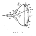
- a color cathode ray tube apparatus of self-convergence type 30 which comprises a panel section 36 having a substantially rectangular face plate 32 and a skirt 34 extending from the peripheral edge of the face plate 32, a funnel section 38 connected to the skirt 34 and a neck section 40 formed continuous to the funnel section 38.
- the interior of the color cathode ray tube 30 is held in a vacuum state by means of the panel section 36, the funnel section 38 and the neck section 40.
- an inline type electron gun assembly 42 which generates three electron beams (R), (G) and (B) such that they fall on the same horizontal plane.
- a deflection device 44 which generates deflection magnetic fields.
- a phosphor screen 46 is formed on the inner face of the face plate 32 of the panel section 36.
- the phosphor screen 46 comprises three phosphor layers which are arranged alternately in a stripe fashion and are excited by three electron beams to emit red light, green light and blue light, respectively.
- Within the tube 30 is disposed a rectangular shadow mask 48 so as to face the phosphor screen 46.
- the shadow mask 48 is formed from a thin metal plate and is provided with a great number of slit apertures.
- the shadow mask 48 is used to land the three electron beams from the electron gun assembly 42 on the predetermined phosphor layers.
- a metallic mask frame 50 surrounds the shadow mask 48.
- To the mask frame 50 is welded a plurality of elastic supporting members 52 which are elastically deformable.
- Within the skirt 34 are provided a plurality of panel pins 54 which engage the supporting members 52.
- the deflection device 44 After deflected horizontally and vertically by the non-uniform magnetic field produced by the deflection device 44, the three electron beams (R), (G) and (B) radiated from the electron gun assembly 42 converge towards the slits of the shadow mask 48.
- the color cathode ray tube 30 is of self-convergence type.
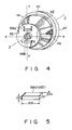
- the deflection device 44 comprises, for example, a pair of horizontal deflection coils 49 wound in a saddle form and mounted in a separator 47 symmetrically with respect to the horizontal axis (X-axis) and a pair of vertical deflection coils 53 wound around the core 51 and mounted on the outer face of a separator 47.
- the horizontal deflection coils 49 of the deflection device 44 mainly produce pincushion type deflection magnetic field which deflects the three electron beams radiated from the electron gun assembly 42 horizontally (that is, in the X directions).
- the vertical deflection coils 53 mainly generates a barrel type deflection magnetic field which deflects the three electron beams vertically (that is, Y directions).
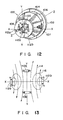
- the color cathode ray tube 30 is provided with a pair of permanent magnets 56a and 56b on an end portion of electron gun side 55 of the deflection device 44 and which are symmetrical with respect to the central axis of the deflection device 44 (which coincides with the Z-axis) and parallel to the XY plane.
- the permanent magnets 56a and 56b are arranged such that their facing poles exhibit reverse magnetic polarities. Each of these magnets assumes a regular parallelepiped shape as shown in Fig. 5 and is made of oxide magnetic substance.
- the magnetic flux density at the central portion of the pole surface of the magnets 56a and 56b is approximately 1500 Gauss/square centimeter.
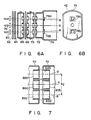
- the electron beam assembly 42 used in the color cathode ray tube 30.
- the electron beam assembly 42 comprises three independent cathodes 60 serially and horizontally arranged, a first grid 62 and a second grid 63 both used for controlling the emitted electrons to form electron beams, a third grid 66, a fourth grid 68 and a fifth grid 70 and a sixth grid 72, the grids 66, 68, 70 and 72 comprising an electron lens unit and being used for accelerating three electron beams (R), (G) and (B) and enabling them to focus, and a convergence cup 74 fixed to the grid 72.
- Heaters 76 are provided for heating the cathodes 60.
- the grids 62, 64 and 68 are formed in a plate form and have electron beam passing holes.
- the grids 66, 70 and 72 are formed in a hollow cylindrical electrodes of a unitary construction and have also electron beam passing holes.
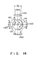
- Fig. 7 shows the grids 70 and 72 of the electron gun assembly 42.
- Center beam passing holes 80a and 80b and side beam passing holes 82a, 82b, 82c and 82d are formed in the grids 70 and 72 so as to be aligned with each other, respectively.
- the space between the side beam passing holes or the distance Sg between a pair of side beams passing the main lens portion is approximately 6.6 mm when the length Sm of the magnet 56 is 6 mm.
- magnetic field controlling elements 78a and 78b made of magnetic substance for correcting comas and which have been changed the after-leakage of the magnetic field of the deflection device 44.
- the permanent magnets 56a and 56b are arranged with their reverse magnetic polarities facing each other.
- the distance between the poles of the magnets 56a and 56b is smaller than the distance between the paired side beams.
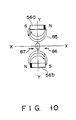
- the vertical deflection coils 52 generate a barrel type vertical deflection magnetic field 83, and the magnets 56a and 56b produce a pincushion type strong magnetic field 84 in the area in which the three electron beams pass.
- the magnets 56a and 56b are not used, therefore, the spots of the three electron beams on the phosphor screen assume an elliptical form with the major axis extending horizontally by Lorentz's forces due to the barrel type vertical deflection magnetic field, and the spots of the side beams are inclined.
- the magnets 56a and 56b are used, however, the electron beams are exerted by vertical Lorentz's forces due to the pincushion type magnetic field, whereby the elliptical deformation and inclination of the spots are corrected.
- the magnetic correcting elements mounted on the bottom of the convergence cup 74 enables to correct the convergence in accordance with the deflection current of the deflection device and also enables the convergence or comas at the periphery of the screen to be corrected such that an improved converging characteristic obtained over the whole screen.
- uniform focusing and converging characteristics are required over the whole area of the screen.
- auxiliary coils are used with which the adjustment of such characteristics over the whole area of the screen is difficult, it is not easy to obtain the uniform focusing and converging characteristics throughout the screen.
- the use of the permanent magnets 56a and 56b facilitates this adjustment.
- a pincushion type magnetic field generated by the paired permanent magnets 56a and 56b is applied to the paired side beams.
- the side beams are exerted by Lorentz's forces in directions as indicated by arrows 86 and 87, respectively.
- the three electron beams (R), (G) and (B) are converged on a point at the center of the screen.
- the static convergence characteristic is improved.
- the conventional electron gun assembly has the following structure: Two adjacent grids constituting the principal lens are arranged such that the side beam passing holes formed in one grid at the side of the screen are separated from the center beam more than those of the other grid at the side of the cathode.
- the electrostatic lens is of asymmetrical type.
- a static electric lens formed between adjacent two grids is disposed so as to be inclined with respect to a pair of side beams.
- the electron gun assembly having such a structure requires electrodes of two kinds of different shapes.
- the electron beam assembly according to this invention does not have a static convergence function and is constructed, for example, such that the three electrons are emitted in parallel to each other.
- the electron gun assembly constructed as described above can be manufactured at a low cost and its assembling accuracies are enhanced.
- a pair of permanent magnets 56a and 56b can be used for controlling not only parallel electron beams but inclined beams when the size, the arrangement and the intensity of magnetic fields of the permanent magnets are properly selected.
- an electron beam is applied to by a pincushion type strong magnetic field 85 produced by a pair of permanent magnets 56a and 56b. Then, the beam spot is exerted by Lorentz's forces and is deformed into an elliptical shape with its major axis extending vertically (that is, in the Y directions).
- these permanent magnets function as an irrotational symmetrical lens which deforms the electron beams into an elliptical form. Therefore, the electron gun assembly should not use an irrotational symmetrical type lens but a rotational symmetrical type lens, whereby it is manufactured at a low cost and has an improved reliability.
- the distance between the poles, the intensity of magnetization, the shape and the like of the paired permanent magnets are arbitrarily selected. Then, the permanent magnets are rendered small and disposed at more places than the auxiliary coils. For example, the permanent magnets can be placed between the electron gun side portion of the deflection device and the core. A deflection device having these permanent magnets is shown in Fig. 11. The permanent magnets 56a and 56b are arranged between the deflection device 44 and the electron gun assembly 42.
- a deflection device 100 of the second embodiment comprises a pair of horizontal deflection coils 107, for example, wound in a saddle form and mounted in a separator 102 symmetrically with respect the X-axis, and a pair of vertical deflection coils 106 wound around the core 104 and mounted on the outer face of the separator 102.
- the horizontal deflection coil 107 mainly generates a pincushion type deflection field for deflecting horizontally (in the X direction) the three electron beams emitted from the electron gun assembly.
- the vertical deflection coil 106 produces mainly a barrel type deflection magnetic field for deflecting the three electron beams in the direction (the Y direction) perpendicular to the direction in which the three electron beams are arranged.
- a pair of permanent magnets 110a and 110b are mounted symmetrically with respect to the central axis (that is, the Z-axis) and are disposed in parallel to the XZ plane with their middle portions located on the Y-axis; and, similarly, a pair of permanent magnets 112a and 112b are mounted symmetrically with respect to the central axis and are disposed in parallel to the YZ plane with their middle portions located on the X-axis).
- the permanent magnets 110a, 110b, 112a and 112b are rectangular and are made of oxide magnetic substance.
- the magnetic flux density at the central portion of the pole surfaces of the permanent magnets 110a and 110b is 1500 Gauss/square centimeter, while those of the permanent magnets 112a and 112b is 1300 Gauss/square centimeter.
- the permanent magnets 110a and 110b arranged as described above generates a pincushion type strong magnetic field, in addition to a barrel type vertical deflection magnetic field generated by the vertical deflection coils.
- the electron beams are exerted not only by the Lorentz's forces due to the barrel type magnetic field but also by the Lorentz's forces which deform the spots of the electron beams into an elliptical shape with their major axis extending vertically.
- the beam spots are prevented from being deformed on the screen into an elliptical form with their major axis extending horizontally, and the inclination of the spots of the paired side beams is also avoided.
- the pair of the permanent magnets 112a and 112b generate a pincushion type magnetic field 116 directed in the same direction of the horizontal deflection magnetic field 114 produced by the horizontal deflection coils 107.
- magnetic field 118 is generated between the magnets 112a and 112b as one party and the magnets 110a and 110b as the other party.
- the magnetic field 118 exerts Lorentz's forces in the directions opposite to those in which the paired side beams are inclined due to the vertical deflection magnetic field, so as to effectively compensate the inclination of the spots.
- the length Sm of the permanent magnets 110a and 110b should be shorter than the distance Sg between the side beams in order to effectively act the magnetic field 118 on the paired side beams.
- a pair of side beams approach the center beam by the pincushion type magnetic field generated by the permanent magnets 110a and 110b, while the side beams are separated from the center beam by the pincushion type magnetic field generated by the permanent magnets 112a and 112b. Therefore, the deflection device 100 cooperates with an electron gun assembly which is different from the first embodiment of the electron gun assembly and is inclined so that the side beams are directed to the center of the phosphor screen 46.
- comas are reduced by correcting the converging characteristic at the periphery of the screen by means of the electron gun assembly. Further, the distances of the permanent magnets, the intensities of magnetization and shapes of the magnets are selected without any limitations. In other words, since the magnets can be set at various places, the deflection device can be made small.
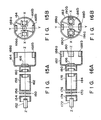
- Figs. 15A and 15B show a third embodiment of this invention in which an electron gun assembly is provided with permanent magnets.
- the electron gun assembly 150 of this invention comprises three independent cathodes 152 arranged in parallel to each other on a horizontal plane including the X-axis, an electron beam generator having a first grid 154 and a second grid 156 both for controlling electrons emitted from the cathodes 152, and a lens unit having a third grid 158 and a fourth grid 160 both for accelerating and focusing three electron beams emitted from the electron beam generator.
- the electron gun assembly 150 is of bipotential type and has a convergence cup 164 connected to the fourth grid 160.
- Magnetic field control elements 166a and 166b made of magnetic substance surround side beam passing holes formed in the bottom of the convergence cup 164.
- a pair of permanent magnets 168a and 168b symmetrically with respect the central axis 162 (Z-axis) of the electron gun assembly 150 such that their facing poles have opposite polarities.
- the distance between the poles of each permanent magnet is smaller than the distance between the side beams.
- Figs. 16A and 16B show a fourth embodiment of this invention in which a bipotential type electron gun assembly similar to that used in the third embodiment is employed.
- the electron gun assembly 170 comprises cathodes 172, a first grid 174, a second grid 176, a third grid 178, a fourth grid 180 and a convergence cup 182.
- On the bottom of the convergence cup 182 are mounted magnetic field control elements 186a and 186b made of magnetic substance.
- Two pairs of permanent magnets 188a and 188b and 190a and 190b are arranged symmetrically with respect to the central axis 184 (Z-axis) of the electron gun assembly 180 within the convergence cup 182 such that the facing poles of each pair of the permanent magnets have reverse polarities.
- the magnets 188a and 188b are arranged in parallel to the XZ plane, whereas the magnets 190a and 190b are arranged in parallel to the YZ plane.
- the length of the vertical permanent magnets 188a and 188b is smaller than the distance between a pair of side beams which have passed the electron lens unit.
- the magnetic flux density of the pole surface of the permanent magnets 188a and 188b is larger than that of the permanent magnets 190a and 190b.
- the magnets 188a and 188b generate a strong pincushion magnetic field than the magnets 190a and 190b.
- the permanent magnets are mounted on the inner periphery of the convergence cup in the third and fourth embodiments. However, they can be arranged on the grids which form the lens unit of the electron gun assembly. When, however, the pincushion type magnetic field produced by the permanent magnets are subject to the lens unit of the electron gun assembly, the side beams do not pass the center of the lens unit, and coma aberration occur. Therefore, it is necessary to provide permanent magnets on the lens unit in order to eliminate the effect of the pincushion type magnetic field produced by the permanent magnets.
- This invention is not limited to the above-mentioned embodiments but is applicable to color cathode ray tubes or color cathode ray tube apparatuses having electron gun assemblies.
- the magnetic control elements are not limited to those of the embodiments and can assume various shapes according to the kinds of the color cathode tubes and/or the deflection devices.
Applications Claiming Priority (2)
| Application Number | Priority Date | Filing Date | Title |
|---|---|---|---|
| JP15697488 | 1988-06-27 | ||
| JP156974/88 | 1988-06-27 |
Publications (3)
| Publication Number | Publication Date |
|---|---|
| EP0348912A2 true EP0348912A2 (fr) | 1990-01-03 |
| EP0348912A3 EP0348912A3 (fr) | 1991-07-10 |
| EP0348912B1 EP0348912B1 (fr) | 1997-03-05 |
Family
ID=15639400
Family Applications (1)
| Application Number | Title | Priority Date | Filing Date |
|---|---|---|---|
| EP89111701A Expired - Lifetime EP0348912B1 (fr) | 1988-06-27 | 1989-06-27 | Tube à rayons cathodiques couleur |
Country Status (4)
| Country | Link |
|---|---|
| EP (1) | EP0348912B1 (fr) |
| KR (1) | KR920000940B1 (fr) |
| CN (1) | CN1017483B (fr) |
| DE (1) | DE68927809T2 (fr) |
Cited By (2)
| Publication number | Priority date | Publication date | Assignee | Title |
|---|---|---|---|---|
| EP0456224A2 (fr) * | 1990-05-10 | 1991-11-13 | Kabushiki Kaisha Toshiba | Dispositif de tube à rayons cathodiques en couleurs |
| EP1231625A1 (fr) * | 1998-11-10 | 2002-08-14 | Matsushita Electric Industrial Co., Ltd. | Collet de deviation et tube cathodique couleurs comprenant ledit collet de deviation |
Citations (5)
| Publication number | Priority date | Publication date | Assignee | Title |
|---|---|---|---|---|
| DE1199891B (de) * | 1960-03-31 | 1965-09-02 | Telefunken Patent | Anordnung zur magnetischen Ablenkung von Kathodenstrahlen in Kathodenstrahlroehren |
| DE3146441A1 (de) * | 1980-12-05 | 1982-07-01 | Naamloze Vennootschap Philips' Gloeilampenfabrieken, 5621 Eindhoven | "kathodenstrahlroehre mit einer ablenkeinheit mit einem gefuege aus dauermagneten, das ein statisches mehrpolfeld zum simulieren einer modulation des dynamischen ablenkfeldes erzeugt" |
| JPS59101745A (ja) * | 1982-12-02 | 1984-06-12 | Toshiba Corp | カラ−受像管 |
| EP0243541A2 (fr) * | 1986-04-29 | 1987-11-04 | Koninklijke Philips Electronics N.V. | Tube d'affichage pour télévision en couleurs avec correction de coma |
| EP0310242A1 (fr) * | 1987-08-28 | 1989-04-05 | RCA Thomson Licensing Corporation | Système d'affichage en couleurs comprenant une culasse de déviation autoconvergente produisant une correction de distorsion d'image |
-
1989
- 1989-06-26 CN CN89104457A patent/CN1017483B/zh not_active Expired
- 1989-06-26 KR KR1019890008785A patent/KR920000940B1/ko not_active IP Right Cessation
- 1989-06-27 EP EP89111701A patent/EP0348912B1/fr not_active Expired - Lifetime
- 1989-06-27 DE DE68927809T patent/DE68927809T2/de not_active Expired - Fee Related
Patent Citations (5)
| Publication number | Priority date | Publication date | Assignee | Title |
|---|---|---|---|---|
| DE1199891B (de) * | 1960-03-31 | 1965-09-02 | Telefunken Patent | Anordnung zur magnetischen Ablenkung von Kathodenstrahlen in Kathodenstrahlroehren |
| DE3146441A1 (de) * | 1980-12-05 | 1982-07-01 | Naamloze Vennootschap Philips' Gloeilampenfabrieken, 5621 Eindhoven | "kathodenstrahlroehre mit einer ablenkeinheit mit einem gefuege aus dauermagneten, das ein statisches mehrpolfeld zum simulieren einer modulation des dynamischen ablenkfeldes erzeugt" |
| JPS59101745A (ja) * | 1982-12-02 | 1984-06-12 | Toshiba Corp | カラ−受像管 |
| EP0243541A2 (fr) * | 1986-04-29 | 1987-11-04 | Koninklijke Philips Electronics N.V. | Tube d'affichage pour télévision en couleurs avec correction de coma |
| EP0310242A1 (fr) * | 1987-08-28 | 1989-04-05 | RCA Thomson Licensing Corporation | Système d'affichage en couleurs comprenant une culasse de déviation autoconvergente produisant une correction de distorsion d'image |
Non-Patent Citations (1)
| Title |
|---|
| PATENT ABSTRACTS OF JAPAN, vol. 8, no. 217 (E-270)[1654], 4th October 1984; & JP-A-59 101 745 (TOSHIBA K.K.) 12-06-1984 * |
Cited By (4)
| Publication number | Priority date | Publication date | Assignee | Title |
|---|---|---|---|---|
| EP0456224A2 (fr) * | 1990-05-10 | 1991-11-13 | Kabushiki Kaisha Toshiba | Dispositif de tube à rayons cathodiques en couleurs |
| EP0456224A3 (en) * | 1990-05-10 | 1993-02-24 | Kabushiki Kaisha Toshiba | Color cathode ray tube apparatus |
| EP1231625A1 (fr) * | 1998-11-10 | 2002-08-14 | Matsushita Electric Industrial Co., Ltd. | Collet de deviation et tube cathodique couleurs comprenant ledit collet de deviation |
| EP1231625A4 (fr) * | 1998-11-10 | 2006-08-23 | Matsushita Electric Ind Co Ltd | Collet de deviation et tube cathodique couleurs comprenant ledit collet de deviation |
Also Published As
| Publication number | Publication date |
|---|---|
| EP0348912A3 (fr) | 1991-07-10 |
| KR900000962A (ko) | 1990-01-31 |
| EP0348912B1 (fr) | 1997-03-05 |
| DE68927809T2 (de) | 1997-09-04 |
| KR920000940B1 (ko) | 1992-01-31 |
| CN1039148A (zh) | 1990-01-24 |
| CN1017483B (zh) | 1992-07-15 |
| DE68927809D1 (de) | 1997-04-10 |
Similar Documents
| Publication | Publication Date | Title |
|---|---|---|
| US2752520A (en) | Tri-color kinescope | |
| US3970890A (en) | Plural beam cathode ray tube including an astigmatic electron lens and self-converging | |
| US5663609A (en) | Electron gun assembly having a quadruple lens for a color cathode ray tube | |
| US5262702A (en) | Color cathode-ray tube apparatus | |
| US5177399A (en) | Color cathode ray tube apparatus | |
| KR960004951B1 (ko) | 미스컨버젼스 보정 수단을 갖는 음극선관 | |
| US3639796A (en) | Color convergence system having elongated magnets perpendicular to plane of plural beams | |
| US6329746B1 (en) | Method of correcting deflection defocusing in a CRT, a CRT employing same, and an image display system including same CRT | |
| EP0361455B1 (fr) | Dispositif de tube à rayons cathodiques en couleurs | |
| US5225736A (en) | Color cathode ray tube apparatus | |
| EP0348912B1 (fr) | Tube à rayons cathodiques couleur | |
| US5763993A (en) | Focusing electrode structure for a color cathode ray tube | |
| EP0388901B1 (fr) | Tube à rayons cathodiques en couleurs | |
| JP3034906B2 (ja) | カラー受像管および偏向装置 | |
| US4473773A (en) | In-line type electromagnetic focusing cathode-ray tube | |
| JP2825265B2 (ja) | カラー受像管および偏向装置 | |
| JPH04147545A (ja) | カラー受像管 | |
| USRE29740E (en) | Color cathode ray tube of the plural beam, single electron gun type | |
| JPH07282740A (ja) | カラ−陰極線管用電子銃 | |
| JP2588599B2 (ja) | 陰極線管 | |
| US20020079820A1 (en) | Cathode-ray tube apparatus | |
| JPH06196108A (ja) | 陰極線管 | |
| JP2661059B2 (ja) | 陰極線管 | |
| JPH09259787A (ja) | カラー陰極線管 | |
| JP2862575B2 (ja) | カラー受像管 |
Legal Events
| Date | Code | Title | Description |
|---|---|---|---|
| PUAI | Public reference made under article 153(3) epc to a published international application that has entered the european phase |
Free format text: ORIGINAL CODE: 0009012 |
|
| 17P | Request for examination filed |
Effective date: 19890724 |
|
| AK | Designated contracting states |
Kind code of ref document: A2 Designated state(s): DE FR GB |
|
| PUAL | Search report despatched |
Free format text: ORIGINAL CODE: 0009013 |
|
| AK | Designated contracting states |
Kind code of ref document: A3 Designated state(s): DE FR GB |
|
| 17Q | First examination report despatched |
Effective date: 19931014 |
|
| GRAG | Despatch of communication of intention to grant |
Free format text: ORIGINAL CODE: EPIDOS AGRA |
|
| GRAH | Despatch of communication of intention to grant a patent |
Free format text: ORIGINAL CODE: EPIDOS IGRA |
|
| GRAH | Despatch of communication of intention to grant a patent |
Free format text: ORIGINAL CODE: EPIDOS IGRA |
|
| GRAA | (expected) grant |
Free format text: ORIGINAL CODE: 0009210 |
|
| AK | Designated contracting states |
Kind code of ref document: B1 Designated state(s): DE FR GB |
|
| REF | Corresponds to: |
Ref document number: 68927809 Country of ref document: DE Date of ref document: 19970410 |
|
| ET | Fr: translation filed | ||
| PLBE | No opposition filed within time limit |
Free format text: ORIGINAL CODE: 0009261 |
|
| STAA | Information on the status of an ep patent application or granted ep patent |
Free format text: STATUS: NO OPPOSITION FILED WITHIN TIME LIMIT |
|
| 26N | No opposition filed | ||
| REG | Reference to a national code |
Ref country code: GB Ref legal event code: 746 Effective date: 19981010 |
|
| REG | Reference to a national code |
Ref country code: FR Ref legal event code: D6 |
|
| REG | Reference to a national code |
Ref country code: GB Ref legal event code: IF02 |
|
| PGFP | Annual fee paid to national office [announced via postgrant information from national office to epo] |
Ref country code: DE Payment date: 20070621 Year of fee payment: 19 |
|
| PGFP | Annual fee paid to national office [announced via postgrant information from national office to epo] |
Ref country code: GB Payment date: 20070627 Year of fee payment: 19 |
|
| PGFP | Annual fee paid to national office [announced via postgrant information from national office to epo] |
Ref country code: FR Payment date: 20070608 Year of fee payment: 19 |
|
| GBPC | Gb: european patent ceased through non-payment of renewal fee |
Effective date: 20080627 |
|
| REG | Reference to a national code |
Ref country code: FR Ref legal event code: ST Effective date: 20090228 |
|
| PG25 | Lapsed in a contracting state [announced via postgrant information from national office to epo] |
Ref country code: DE Free format text: LAPSE BECAUSE OF NON-PAYMENT OF DUE FEES Effective date: 20090101 |
|
| PG25 | Lapsed in a contracting state [announced via postgrant information from national office to epo] |
Ref country code: GB Free format text: LAPSE BECAUSE OF NON-PAYMENT OF DUE FEES Effective date: 20080627 |
|
| PG25 | Lapsed in a contracting state [announced via postgrant information from national office to epo] |
Ref country code: FR Free format text: LAPSE BECAUSE OF NON-PAYMENT OF DUE FEES Effective date: 20080630 |