EP0348837A2 - Verfahren zur Herstellen von Kolbenringen - Google Patents
Verfahren zur Herstellen von Kolbenringen Download PDFInfo
- Publication number
- EP0348837A2 EP0348837A2 EP89111454A EP89111454A EP0348837A2 EP 0348837 A2 EP0348837 A2 EP 0348837A2 EP 89111454 A EP89111454 A EP 89111454A EP 89111454 A EP89111454 A EP 89111454A EP 0348837 A2 EP0348837 A2 EP 0348837A2
- Authority
- EP
- European Patent Office
- Prior art keywords
- strip
- ring
- curvature
- bending means
- radius
- Prior art date
- Legal status (The legal status is an assumption and is not a legal conclusion. Google has not performed a legal analysis and makes no representation as to the accuracy of the status listed.)
- Granted
Links
- 238000000034 method Methods 0.000 title claims abstract description 18
- 238000004519 manufacturing process Methods 0.000 title claims abstract description 12
- 239000002184 metal Substances 0.000 claims abstract description 44
- 239000000470 constituent Substances 0.000 claims abstract description 8
- 238000005452 bending Methods 0.000 claims description 45
- 230000015572 biosynthetic process Effects 0.000 claims description 13
- 238000002485 combustion reaction Methods 0.000 claims description 6
- 230000008859 change Effects 0.000 description 6
- 238000010586 diagram Methods 0.000 description 5
- 230000003252 repetitive effect Effects 0.000 description 4
- 238000011282 treatment Methods 0.000 description 3
- 230000000694 effects Effects 0.000 description 2
- 238000007493 shaping process Methods 0.000 description 2
- 230000009471 action Effects 0.000 description 1
- 230000002411 adverse Effects 0.000 description 1
- 238000006243 chemical reaction Methods 0.000 description 1
- 230000006870 function Effects 0.000 description 1
- 238000010438 heat treatment Methods 0.000 description 1
- 230000007246 mechanism Effects 0.000 description 1
- 230000008569 process Effects 0.000 description 1
- 230000004044 response Effects 0.000 description 1
- 238000000926 separation method Methods 0.000 description 1
- 230000000007 visual effect Effects 0.000 description 1
Images


Classifications
-
- B—PERFORMING OPERATIONS; TRANSPORTING
- B21—MECHANICAL METAL-WORKING WITHOUT ESSENTIALLY REMOVING MATERIAL; PUNCHING METAL
- B21D—WORKING OR PROCESSING OF SHEET METAL OR METAL TUBES, RODS OR PROFILES WITHOUT ESSENTIALLY REMOVING MATERIAL; PUNCHING METAL
- B21D7/00—Bending rods, profiles, or tubes
- B21D7/08—Bending rods, profiles, or tubes by passing between rollers or through a curved die
-
- B—PERFORMING OPERATIONS; TRANSPORTING
- B21—MECHANICAL METAL-WORKING WITHOUT ESSENTIALLY REMOVING MATERIAL; PUNCHING METAL
- B21D—WORKING OR PROCESSING OF SHEET METAL OR METAL TUBES, RODS OR PROFILES WITHOUT ESSENTIALLY REMOVING MATERIAL; PUNCHING METAL
- B21D53/00—Making other particular articles
- B21D53/16—Making other particular articles rings, e.g. barrel hoops
-
- F—MECHANICAL ENGINEERING; LIGHTING; HEATING; WEAPONS; BLASTING
- F16—ENGINEERING ELEMENTS AND UNITS; GENERAL MEASURES FOR PRODUCING AND MAINTAINING EFFECTIVE FUNCTIONING OF MACHINES OR INSTALLATIONS; THERMAL INSULATION IN GENERAL
- F16J—PISTONS; CYLINDERS; SEALINGS
- F16J9/00—Piston-rings, e.g. non-metallic piston-rings, seats therefor; Ring sealings of similar construction
- F16J9/12—Details
-
- Y—GENERAL TAGGING OF NEW TECHNOLOGICAL DEVELOPMENTS; GENERAL TAGGING OF CROSS-SECTIONAL TECHNOLOGIES SPANNING OVER SEVERAL SECTIONS OF THE IPC; TECHNICAL SUBJECTS COVERED BY FORMER USPC CROSS-REFERENCE ART COLLECTIONS [XRACs] AND DIGESTS
- Y10—TECHNICAL SUBJECTS COVERED BY FORMER USPC
- Y10T—TECHNICAL SUBJECTS COVERED BY FORMER US CLASSIFICATION
- Y10T29/00—Metal working
- Y10T29/49—Method of mechanical manufacture
- Y10T29/49229—Prime mover or fluid pump making
- Y10T29/49274—Piston ring or piston packing making
- Y10T29/49279—Piston ring or piston packing making including rolling or die forming, e.g., drawing, punching
-
- Y—GENERAL TAGGING OF NEW TECHNOLOGICAL DEVELOPMENTS; GENERAL TAGGING OF CROSS-SECTIONAL TECHNOLOGIES SPANNING OVER SEVERAL SECTIONS OF THE IPC; TECHNICAL SUBJECTS COVERED BY FORMER USPC CROSS-REFERENCE ART COLLECTIONS [XRACs] AND DIGESTS
- Y10—TECHNICAL SUBJECTS COVERED BY FORMER USPC
- Y10T—TECHNICAL SUBJECTS COVERED BY FORMER US CLASSIFICATION
- Y10T29/00—Metal working
- Y10T29/49—Method of mechanical manufacture
- Y10T29/49789—Obtaining plural product pieces from unitary workpiece
Definitions
- This invention relates to a method for the manufacture of rings and, in particular, piston rings for internal combustion engines.
- Such piston rings are commonly formed from metal, and have a generally circular profile but with two free ends which are adjacent one another and separated by a gap.
- each piston ring is received in a groove provided in a piston for the internal combustion engine, where the purpose of the piston ring is to provide a seal between the piston and the interior surface of the cylinder within which the piston is to move.
- the actual profile of a piston ring is not, however, perfectly circular, allowance having to be made for variation in bending moment around the circumference of the ring required to achieve an appropriate, eg uniform, radially outward pressure pattern when the ring is on a piston and fitted into a cylinder bore.
- the manufacture of rings to which the present invention relates also includes the manufacture of rings to be incorporated in hydraulic seals, and compressors, for example. Such other types of rings also each have a predetermined non-circular form, with a gap separating two free ends.
- Such other types of rings also each have a predetermined non-circular form, with a gap separating two free ends.
- German OLS 2 838 128 discloses the shaping of wire into rings using a deflector element (eg a roller) which may be offered up to the wire as a function of the desired outline of a piston ring.
- Published UK Patent Application 2 155 828A discloses a machine for producing from a metal strip piston rings of a predetermined profile for internal combustion engines, comprising at least two guides for guiding the metal strip into a generally circular profile, which is then separated from the remainder of the strip to form a piston ring, at least one of said guides being movable relatively to the other guide or guides during said formation of a piston ring to vary the profile of the strip around the piston ring, and a control system for producing digital signals corresponding to a required piston ring profile, the digital signals controlling the movement of said at least one movable guide during formation of a piston ring from said metal strip to produce a piston ring having the required profile therearound.
- a deflector element eg a roller
- a method for the manufacture of piston rings for use in internal combustion engines at least including providing rings having a predetermined non-circular profile, by feeding a metal strip into a guide means to align the strip and feed the strip into a first bending means, bending the strip in said first bending means into a regular curve of a predetermined radius, and feeding said curved strip into a second bending means operable to vary the radius of curvature of the strip fed thereto, the strip being bent by said first bending means to a uniform radius of at least 2 percent below the minimum radius of curvature in said predetermined ring profile, and then the strip being bent by said second bending means throughout the formation of each ring to increase the radii of curvature of all the constituent portions of the strip forming the ring to the values required in said predetermined non-circular profile.
- the method of the invention facilitates the production of rings of greater consistency and accuracy than the method disclosed in UK Patent Application No 2 155 828A in which the metal strip is not bent beyond the maximum curvature required in the ring.
- the uniform radius of curvature of the metal strip induced in the first bending means will generally be well above 2% less than the minimum radius of curvature needed in the predetermined ring profile.
- the ratio between these two radii of curvature may be in the range 98:100 to 2:5.
- the ratio of the uniform radius of curvature of the metal strip induced by the first bending means to the minimum radius of curvature needed in the predetermined ring profile is in the range 3:4 to 1:2.
- the metal strip to be bent is driven in a straight line between guides constituting the guide means.
- the strip In the first bending means the strip is forced against an abutment having a location in relation to the position of a fulcrum pin chosen such that the strip is bent around the fulcrum pin to a greater extent than is required in the predetermined ring profile, and in the second bending means the curved metal strip from said first bending means is passed around a movable finger which, throughout the formation of each ring, urges the strip outwardly to increase the radii of curvature of all the constituent portions of the strip forming the ring by the desired amounts.
- Strip is fed through said first and second bending means until at least a required ring has been produced, deflector means being used to direct the leading portion of the strip of each ring into a plane adjacent to that of the strip feeding into the bending means; and each ring produced is severed from the oncoming strip, the point of severence preferably being adjusted, so as to provide the desired gap in the ring.
- the rings produced are severed one by one without arresting the feeding of the strip into the bending means.
- the predetermined non-circular profile of the ring produced at this point may not be the profile of the finished piston ring since in many cases the rings produced at this stage will be subjected to further treatment before use, eg heat treatment during nitro-carburising. We have found that such treatment may result in shape changes in the rings, and the predetermined profile to which the rings are bent in accordance with the present invention may be so that compensation is provided for any such subsequent changes in shape of the rings.
- an apparatus for bending metal strip consists essentially of feed rollers 1 for metal strip, a guide 2 for maintaining metal strip aligned in a straight path, a first bending means composed of a fulcrum pin 3 and an abutment 4, and a second bending means composed of a movable finger 5 arranged to co-operate with the abutment 4.
- a high speed cropper 6 is also provided to sever the rings produced.
- the metal strip passes alongside the fulcrum pin 3 and is forced against the abutment 4. It will be appreciated that the abutment 4 exerts a bending force on the metal strip 7 in the plane of its wider dimension, so that the strip is bent about the fulcrum pin 3.
- a non-circular profile is the predetermined target shape for the rings being produced. This is settled according to the ring shape needed for the particular use envisaged, taking into account further shape changes which may be induced by subsequent ring treatments.
- the location of the abutment 4 in relation to the fulcrum pin 3 is chosen so that a desired uniform radius of curvature is induced in the metal strip between the fulcrum pin 3 and the abutment 4. This radius of curvature is at least 2% less than the minimum radius needed in the predetermined ring profile.
- the metal strip 7 thence moves from the abutment 4 to a movable finger 5 exerting a radially outward pull on the strip, throughout the formation of each ring, to increase the radii of curvature of all the constituent portions of the strip forming the ring to the values required in the predetermined profile.
- the position of the movable finger 5 is computer controlled, as described below, and is varied over a range to produce the predetermined non-circular profile as a length of metal strip required to form a desired ring passes around it.
- the movable finger 5 is mounted on a carrier 8 which is pivotally attached via an adjustable turnbuckle 9 to a lever 10.
- the lever 10 is pivoted about a pin 11 and the end of the lever opposite to the turnbuckle is provided with a roller 12 which bears on an eccentric 13 rotatable about a shaft 14.
- the eccentric 13 is rotated to any angular location by a servo-motor, and a computer is used to generate signals controlling the position of the eccentric 13 by means of the servo-motor, as described below, and at any given instant during the passage of a length of metal strip corresponding to a ring over the movable finger 5.
- the metal strip is deflected slightly after bending is complete so that the ring being produced will overlay the oncoming strip.
- the deflection is into a plane adjacent that of the feed of metal strip and is achieved by deflector plates (not shown in the diagrams) to produce the result illustrated diagrammatically in Figure 2.
- Figure 2 shows in diagrammatic form the progress of a metal strip as it is transformed from a straight strip into a ring.
- the strip is bent initially between points A and B to a fixed extent and then its radius of curvature is increased between B and C by varying amounts.
- a ring is produced which is deflected to overlay the strip being fed in.
- a high speed cropper 6 shown in Figure 1).
- the point at which the ring is severed is that at which the free ends of the severed ring are at the correct position on the ring profile and have the correct separation.
- the usual shape of a piston ring is illustrated in Figure 4 from which it can be seen that the ring has a minimum curvature (maximum radius) at position Y opposite the gap and maximum curvature (minimum radius) at position Z adjacent the gap.
- the strip 7 Since during the second bending operation two simultaneous movements are taking place in that the metal strip 7 is moving forward and the movable finger 5 is moving radially inwardly and outwardly to vary the degree of bending on the strip, it is only possible to say that the strip assumes a given radius, eg its maximum radius, somewhere between B and C in Figure 2. Therefore in the present invention the severance point, point X in Figure 2 is determined expermimentally for each ring profile, and each type of metal strip, since the elasticity of the metal will affect where between B and C a final radius is achieved. The determination of the severance point can be readily achieved by trial and error in each case.
- the severance takes place without stopping feed of the metal strip so that preferably the point of severance is located far enough away from point C to allow a slight arrest of movement of the strip, eg 35 milliseconds, to be taken up by the elasticity of the strip without disturbing the bending process.
- a control system for the apparatus described above comprises an input-output interface device 20 communicating with a control processor 22 via a memory 24.
- the control processor 22 is arrange to receive data from, and to transmit data to, the memory 24, and may comprise a type 68000 microprocessor supplied by Motorola Inc.
- the input-output device 20 operates in a manner compatible with the control processor 22, and, in particular is arranged to transmit data to, and receive data from, the memory 24. Further, the input-output device 20 is to receive input data IN, for example, from an operator, say, via a keyboard (not shown); and is to provide output data OUT for the operator, for example, the device 20 driving a visual display unit (not shown).
- the control processor 22 provides information, via a digital-to-analogue converter (DAC)26, to control a servo-motor 28 for feeding the metal strip 7 through the apparatus.
- DAC digital-to-analogue converter
- the servo-motor 28 drives the feed rollers 1.
- the feed rollers 1 are coupled operably to a transducer, comprising an encoder 30, the encoder providing signals to the control processor 22, each such signal being representative of the strip length having passed through the rollers.
- the control processor 22 also provides information, via a DAC 32, to control a servo motor 34 for varying the position of the movable finger 5, and so to control the radius of curvature of the strip portion instantaneously at the movable finger.
- the servo-motor 34 causes rotation of the eccentric 13, as described above.
- One convenient part of the movable finger control mechanism is coupled operably to a transducer, comprising an encoder 36, providing signals each representative of the instantaneous position of the finger.
- the information representative of the position of the finger 5 is supplied by the encoder 36 to the control processor 22.
- Stored in the memory 24 is data defining the predetermined non-circular profile of a required ring.
- This profile data is obtained by employing, say, known finite element analysis techniques.
- There are addressable locations in the memory in this respect, at each such location the appropriate profile data for a 0.1° of arc of the ring, (or for a portion of the ring subtending an angle of 0.1° at the centre of curvature of the portion), is stored.
- profile data comprising the radius of curvature required for the corresponding portion of the ring, and the length of the strip 7 required in forming the part of the ring upto, and including, this ring portion.
- the first location has store thereat the appropriate profile data corresponding to the leading portion of the strip 7 to form the ring.
- the information stored at the CROPPING loction is provided as a result of experimentation when setting-up the apparatus to produce the ring, and is entered into the memory 24 via the operator's keyboard.
- the encoder 30 detects the instantaneous length of the strip having passed through the feed rollers.
- the corresponding length of the strip of use in the control of the formation of the ring, and stored at each profile data location in the memory takes into account the spacing between the two encoders 30 and 36 in the apparatus, the dimensions of relevant parts of the apparatus, and the shape of the strip as it passes between the feed rollers 1 and the movable finger 5.
- the control processor 22 is arranged to convert the stored strip length values to values corresponding to those detectable by the encoder 30, so that a direct comparison can be made therebetween.
- control processor also being arranged to covert any demanded change in the velocity of feeding of the strip, as described below, and as determined by the control processor, to a corresponding output signal, to cause the appropriate change of the drive of the servo-motor 28, and to effect the demanded change in the feeding velocity of the strip.
- the encoder 36 does not detect the instantaneous position of the movable finger 5, but a magnitude in a predetermined relationship thereto; and the position of the movable finger is in a predetermined relationship to the radius of curvature of the strip portion provided by bending the strip portion of the movable finger.
- the control processor 22 is arranged to convert the stored radius of curvature values to values corresponding to those detectable by the encoder 36, so that a direct comparison can be made therebetween, as described below.
- control processor also being arranged to convert any demanded change of the radius of curvature value, as described below, and as determined by the control processor, to a corresponding output signal, to cause the appropriate actuation of the servo-motor 34, and to effect the change in the radius of curvature.
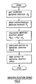
- control processor 22 The manner of operation of the control processor 22 partially is shown in the flow charts of Figures 7 to 9.
- control processor From the reading of the value of the radius of curvature of the first ring portion, and stored at the first location of the ring profile data, the control processor obtains the expected value P d of the output of the encoder 36 corresponding to the required first position of the movable finger 5.
- control processor then enters a routine which is repeated in a repetitive manner.
- This part of the operation of the control processor is controlled by a clock, and each constituent routine of the operation is entered after each millisecond during the formation of the required ring.
- a strip velocity servo loop is in operation.
- the control processor obtains the currently expected velocity of the strip feed V d .
- the control processor obtains the instantaneous actual strip velocity V c , by immediately previously having read, and stored, two outputs of the encoder 30 with a millisecond interval therebetween, and by subtracting the first such encoder output from the second output.
- Any error V err between the currently expected velocity V d and the instantaneous actual velocity V c is determined by the control processor; and the control processor derives the corresponding change in speed of the servo-motor 28 in order to tend to eliminate V err .
- the appropriate output signal is supplied by the control processor to the servo-motor 28, via the DAC 26. This completes the operation of the strip velocity servo loop in the first routine.
- the control processor also reads the instantaneous actual output P i of the encoder 36, possibly, comprising the position of the encoder during the formation of the final portion of the previous ring, and read, and stored, by the control procesor.
- control processor calculates any error P err between P d and P i ; and derives the corresponding amount of actuation of the servo-motor 34 in order to tend to eliminate P err .
- the appropriate output signal is supplied by the control processor to the servo-motor 34, via the DAC 32. This completes the operation of the bending position servo loop in the first routine.
- control processor After the end of the 250 microsecond period, with the required strip feed velocity, and the required position of the movable finger 5, demanded, and within the final 750 microsecond period of the first clocked routine, the control processor performs a strip tracking task, as indicated in the flow chart of Figure 7.
- the strip tracking task comprises a sub-routine to be performed repetitively until interrupted at a predetermined point in the routine, or until it is determined that the instantaneous strip length having been fed through the feed rollers 1 is equal to the strip length value stored at the first profile data location in the memory.
- control processor 22 reads the instantaneous output of the encoder 30, and representative of the strip length as having passed through the feed rollers 1.
- the control processor 22 decides whether, or not, the thus instantaneously detected strip length as having passed through the feed rollers is equal to the value of the strip length expected to have passed through the feed rollers, and stored at the first memory located currently being addressed. This completes the sub-routine. If the decision is negative, the output of the encoder 30 is read again; and the control processor again is required to decide whether, or not, the same criterion has been obtained. The sub-routine is repeated in a repetitive manner until the decision is affirmative; or until the repetition of the sub-routine is interrupted, as referred to above.
- control processor addresses the second location of profile data within the memory 24, at which location is stored profile data relating to the second 0.1° of arc of the ring.
- profile data relating to the required radius of curvature of the second 0.1° of arc of the ring is read by the control processor.
- the control processor decides whether, or not, the information defining the portion of the ring, comprising the appropriate 0.1° of arc of the ring, and stored at the CROPPING location within the memory 24, is the same as the information defining the second portion of the ring, and stored at the second location of the profile data within the memory.
- control processor decides whether, or not, the second location of the profile data within the memory is the final such location of the profile data of the ring.
- the second routine is commenced, under the control of the clock, and at the end of the one millisecond period allowed for the first routine.
- the strip velocity servo loop again is operated in the manner indicated in the flow chart of Figure 8. This time the instantaneous actual strip velocity V c is determined by using the appropriate output of the encoder 30 read, and stored, in the first routine.
- the sub-routine comprising the strip tracking task is performed, until the instantaneous strip length having been fed through the feed rollers is equal to the strip length value stored at the second profile data location in the memory; or until the sub-routine is interrupted, as referred to above.
- the second routine is completed, including reading the profile date at the third location in the memory.
- the routine is repeated, in a repetitive manner, whilst the ring is being formed with the predetermined non-circular profile in accordance with the profile data stored in the memory 24. This repetition occurs until the control processor 22 decides that the information defining a portion of the ring, and stored at the CROPPING location within the memory 24, is the same as the information defining the portion of the ring at the profile data location within the memory currently being addressed by the control processor. In response to this affirmative decision, the control processor causes the cropper 6 to be actuated. This cropping action of the previously formed ring does not interfere adversely with the formation of the ring being produced. In the same routine, inevitably, a further decision is made that the simultaneously addressed location of the profile data in the memory 24 is not the final such location.
- routine is continued to be repeated, in a repetitive manner; but the cropper 6 is not actuated again until after the ring being formed is completed.
- control processor 22 Normally the control processor 22 then repeats the above operation, without interruption of the wire feed to the bending means, and in order to form a subsequent ring.
Landscapes
- Engineering & Computer Science (AREA)
- Mechanical Engineering (AREA)
- General Engineering & Computer Science (AREA)
- Bending Of Plates, Rods, And Pipes (AREA)
Applications Claiming Priority (4)
| Application Number | Priority Date | Filing Date | Title |
|---|---|---|---|
| GB888815604A GB8815604D0 (en) | 1988-06-30 | 1988-06-30 | Method for manufacture of piston rings |
| GB8815604 | 1988-06-30 | ||
| GB8821996 | 1988-09-19 | ||
| GB888821996A GB8821996D0 (en) | 1988-06-30 | 1988-09-19 | Method for manufacture of piston rings |
Publications (3)
| Publication Number | Publication Date |
|---|---|
| EP0348837A2 true EP0348837A2 (de) | 1990-01-03 |
| EP0348837A3 EP0348837A3 (en) | 1990-09-05 |
| EP0348837B1 EP0348837B1 (de) | 1993-11-03 |
Family
ID=26294104
Family Applications (1)
| Application Number | Title | Priority Date | Filing Date |
|---|---|---|---|
| EP89111454A Expired - Lifetime EP0348837B1 (de) | 1988-06-30 | 1989-06-23 | Verfahren zur Herstellen von Kolbenringen |
Country Status (4)
| Country | Link |
|---|---|
| US (1) | US4937937A (de) |
| EP (1) | EP0348837B1 (de) |
| DE (1) | DE68910395T2 (de) |
| GB (1) | GB2220600B (de) |
Cited By (2)
| Publication number | Priority date | Publication date | Assignee | Title |
|---|---|---|---|---|
| WO1997000146A1 (en) * | 1995-06-15 | 1997-01-03 | T & N Technology Limited | Spring coiling |
| CN102989847A (zh) * | 2012-11-30 | 2013-03-27 | 中国北车集团大连机车车辆有限公司 | 机车车钩提环加工用工装及其制造工艺 |
Families Citing this family (8)
| Publication number | Priority date | Publication date | Assignee | Title |
|---|---|---|---|---|
| GB8821995D0 (en) * | 1988-09-19 | 1988-10-19 | T & N Technology Ltd | Improvements in/relating to piston rings |
| EP0416046B1 (de) * | 1988-12-01 | 1992-11-04 | AE PISTON PRODUCTS LIMITED (FORMERLY HEPWORTH & GRANDAGE LTD.) | Kolbenring |
| US5752705A (en) * | 1988-12-01 | 1998-05-19 | Ae Piston Products Limited | Piston rings |
| GB9205258D0 (en) * | 1992-03-11 | 1992-04-22 | T & N Technology Ltd | Manufacture of piston rings |
| US5809643A (en) * | 1995-12-22 | 1998-09-22 | Swick; E. Grant | Method for making piston rings |
| US6053988A (en) * | 1995-12-22 | 2000-04-25 | Swick; E. Grant | Method for making piston rings |
| GR1006845B (el) * | 2003-10-02 | 2010-07-05 | Αναγνωστοπουλος, Αντωνιος Παναγιωτη | Μεθοδος και συστημα παραγωγης ελατηριων απο συρμα κυκλικης ή αλλης διατομης |
| DE102012212713A1 (de) * | 2012-07-19 | 2014-01-23 | Otto Bihler Handels-Beteiligungs-Gmbh | Rollbiegeverfahren und -vorrichtung |
Family Cites Families (9)
| Publication number | Priority date | Publication date | Assignee | Title |
|---|---|---|---|---|
| US3778877A (en) * | 1970-09-28 | 1973-12-18 | Mc Donnell Douglas Corp | Method of making piston ring expander |
| SU543466A2 (ru) * | 1975-04-03 | 1977-01-25 | Физико-технический институт АН Белорусской ССР | Самовращающийс чашечный резец |
| SU640798A1 (ru) * | 1977-02-08 | 1979-01-05 | Ордена Трудового Красного Знамени Научно-Исследовательский Институт Технологии Автомобильной Промышленности | Автомат дл навивки колец из ленты |
| DE2838128C3 (de) * | 1978-09-01 | 1981-10-22 | Goetze Ag, 5093 Burscheid | Vorrichtung zum Herstellen von unrunden Kolbenringen aus Metalldraht oder -band |
| US4365492A (en) * | 1980-06-25 | 1982-12-28 | Intercole Bolling Corp. | Ring former and cutoff |
| JPS594934A (ja) * | 1982-07-01 | 1984-01-11 | Nippon Piston Ring Co Ltd | ピストンリングの製造方法 |
| US4497102A (en) * | 1983-07-01 | 1985-02-05 | Nippon Piston Ring Co., Ltd. | Process for manufacturing a piston ring |
| GB8407712D0 (en) * | 1984-03-24 | 1984-05-02 | Ae Plc | Piston rings for ic engines |
| DE3632346A1 (de) * | 1986-09-24 | 1988-04-07 | Goetze Ag | Verfahren und maschine zur herstellung von kolbenringen |
-
1989
- 1989-06-23 EP EP89111454A patent/EP0348837B1/de not_active Expired - Lifetime
- 1989-06-23 GB GB8914440A patent/GB2220600B/en not_active Expired - Lifetime
- 1989-06-23 DE DE68910395T patent/DE68910395T2/de not_active Expired - Fee Related
- 1989-06-27 US US07/371,792 patent/US4937937A/en not_active Expired - Fee Related
Cited By (3)
| Publication number | Priority date | Publication date | Assignee | Title |
|---|---|---|---|---|
| WO1997000146A1 (en) * | 1995-06-15 | 1997-01-03 | T & N Technology Limited | Spring coiling |
| CN102989847A (zh) * | 2012-11-30 | 2013-03-27 | 中国北车集团大连机车车辆有限公司 | 机车车钩提环加工用工装及其制造工艺 |
| CN102989847B (zh) * | 2012-11-30 | 2014-11-05 | 中国北车集团大连机车车辆有限公司 | 机车车钩提环制造工艺 |
Also Published As
| Publication number | Publication date |
|---|---|
| EP0348837A3 (en) | 1990-09-05 |
| US4937937A (en) | 1990-07-03 |
| DE68910395D1 (de) | 1993-12-09 |
| GB2220600B (en) | 1992-01-08 |
| EP0348837B1 (de) | 1993-11-03 |
| GB8914440D0 (en) | 1989-08-09 |
| GB2220600A (en) | 1990-01-17 |
| DE68910395T2 (de) | 1994-06-01 |
Similar Documents
| Publication | Publication Date | Title |
|---|---|---|
| EP0348837B1 (de) | Verfahren zur Herstellen von Kolbenringen | |
| CA1259172A (en) | Manufacture of piston rings | |
| EP0661115B1 (de) | Rohrbiegevorrichtung | |
| US5068963A (en) | Piston rings | |
| JP4366755B2 (ja) | パイプ曲げ加工方法および装置 | |
| JPH06315732A (ja) | バネ切断機構 | |
| US5752705A (en) | Piston rings | |
| JPH11226656A (ja) | 押曲げ式熱間べンダー | |
| US4675490A (en) | Method and apparatus for controlling electrode position in an electric discharge machine by counting feedback pulses and repeatedly adding the count | |
| EP0673290B1 (de) | Herstellen von kolbenringen | |
| GB2209012A (en) | Boosted drive for pressure die of a tube bender | |
| EP0416046B1 (de) | Kolbenring | |
| JP2869626B2 (ja) | 直線切断機及び走間切断方法 | |
| CN116766300B (zh) | 切割机构的控制方法 | |
| JP2831234B2 (ja) | 曲げ加工装置の自動曲げ制御方法及び装置 | |
| SU1131609A2 (ru) | Автомат листоштамповочный | |
| SU673344A1 (ru) | Профилегибочный горизонтальный пресс с программным управлением | |
| SU940923A1 (ru) | Устройство дл центрировани штучных заготовок при гибке | |
| JPH09155448A (ja) | ストリップ巻取り方法及び装置 | |
| JPS59193721A (ja) | ベンダー | |
| JP2004058147A (ja) | 曲げ成形装置 | |
| SU1031650A1 (ru) | Автомат листоштамповочный | |
| SU1355380A1 (ru) | Агрегат продольной резки рулонного материала | |
| JPH09276936A (ja) | 帯刃の曲げ加工装置 | |
| JPS61252016A (ja) | 金属板のスクロ−ル剪断装置 |
Legal Events
| Date | Code | Title | Description |
|---|---|---|---|
| PUAI | Public reference made under article 153(3) epc to a published international application that has entered the european phase |
Free format text: ORIGINAL CODE: 0009012 |
|
| AK | Designated contracting states |
Kind code of ref document: A2 Designated state(s): DE FR IT SE |
|
| PUAL | Search report despatched |
Free format text: ORIGINAL CODE: 0009013 |
|
| AK | Designated contracting states |
Kind code of ref document: A3 Designated state(s): DE FR IT SE |
|
| 17P | Request for examination filed |
Effective date: 19910306 |
|
| 17Q | First examination report despatched |
Effective date: 19930405 |
|
| GRAA | (expected) grant |
Free format text: ORIGINAL CODE: 0009210 |
|
| ITF | It: translation for a ep patent filed | ||
| AK | Designated contracting states |
Kind code of ref document: B1 Designated state(s): DE FR IT SE |
|
| REF | Corresponds to: |
Ref document number: 68910395 Country of ref document: DE Date of ref document: 19931209 |
|
| ET | Fr: translation filed | ||
| PLBE | No opposition filed within time limit |
Free format text: ORIGINAL CODE: 0009261 |
|
| STAA | Information on the status of an ep patent application or granted ep patent |
Free format text: STATUS: NO OPPOSITION FILED WITHIN TIME LIMIT |
|
| 26N | No opposition filed | ||
| EAL | Se: european patent in force in sweden |
Ref document number: 89111454.8 |
|
| PGFP | Annual fee paid to national office [announced via postgrant information from national office to epo] |
Ref country code: FR Payment date: 20000518 Year of fee payment: 12 |
|
| PGFP | Annual fee paid to national office [announced via postgrant information from national office to epo] |
Ref country code: SE Payment date: 20000519 Year of fee payment: 12 |
|
| PGFP | Annual fee paid to national office [announced via postgrant information from national office to epo] |
Ref country code: DE Payment date: 20000524 Year of fee payment: 12 |
|
| PG25 | Lapsed in a contracting state [announced via postgrant information from national office to epo] |
Ref country code: SE Free format text: LAPSE BECAUSE OF NON-PAYMENT OF DUE FEES Effective date: 20010624 |
|
| EUG | Se: european patent has lapsed |
Ref document number: 89111454.8 |
|
| PG25 | Lapsed in a contracting state [announced via postgrant information from national office to epo] |
Ref country code: FR Free format text: LAPSE BECAUSE OF NON-PAYMENT OF DUE FEES Effective date: 20020228 |
|
| PG25 | Lapsed in a contracting state [announced via postgrant information from national office to epo] |
Ref country code: DE Free format text: LAPSE BECAUSE OF NON-PAYMENT OF DUE FEES Effective date: 20020403 |
|
| PG25 | Lapsed in a contracting state [announced via postgrant information from national office to epo] |
Ref country code: IT Free format text: LAPSE BECAUSE OF NON-PAYMENT OF DUE FEES Effective date: 20050623 |