EP0348731A2 - Mât d'acier tubulaire avec rail de montage rapporté pour bloc de connexion - Google Patents
Mât d'acier tubulaire avec rail de montage rapporté pour bloc de connexion Download PDFInfo
- Publication number
- EP0348731A2 EP0348731A2 EP89110734A EP89110734A EP0348731A2 EP 0348731 A2 EP0348731 A2 EP 0348731A2 EP 89110734 A EP89110734 A EP 89110734A EP 89110734 A EP89110734 A EP 89110734A EP 0348731 A2 EP0348731 A2 EP 0348731A2
- Authority
- EP
- European Patent Office
- Prior art keywords
- rail
- mounting rail
- bracket
- opening
- earthing
- Prior art date
- Legal status (The legal status is an assumption and is not a legal conclusion. Google has not performed a legal analysis and makes no representation as to the accuracy of the status listed.)
- Granted
Links
Images

Classifications
-
- H—ELECTRICITY
- H02—GENERATION; CONVERSION OR DISTRIBUTION OF ELECTRIC POWER
- H02B—BOARDS, SUBSTATIONS OR SWITCHING ARRANGEMENTS FOR THE SUPPLY OR DISTRIBUTION OF ELECTRIC POWER
- H02B1/00—Frameworks, boards, panels, desks, casings; Details of substations or switching arrangements
- H02B1/015—Boards, panels, desks; Parts thereof or accessories therefor
- H02B1/04—Mounting thereon of switches or of other devices in general, the switch or device having, or being without, casing
Definitions
- the invention relates to a tubular steel mast with an opening for the assembly and maintenance of cable connections, fuses or the like, which are mounted as a valve block on an insertable on the inner wall opposite the opening, preferably designed as a standard C-rail via slide nuts , with a grounding bracket engaging in the lower end of the mounting rail.
- a Z-shaped angled earthing bracket is welded into the tubular steel mast with one leg in order to hold the lower end of the mounting rail.
- the upper end is held behind a welded-in U-bracket.
- the mounting rail is first pushed upwards through the upper U-bracket and then, when pulled down, pushed onto the end of the earthing bracket located in front of the inner wall.
- the first problem is that both the earthing bracket and the U-shaped upper bracket - to have a large space in between so that larger valve blocks can be used - should be as far apart as possible from each other than the longitudinal extent of the opening of the steel pipe masts.
- This type of assembly is even more cumbersome, since after galvanizing it is not necessary to bring the entire masts to the thread, which means considerable transport costs.
- there is also a limitation of the total length of the valve blocks to be used which in no way can be longer than the distance of the earthing bracket from the upper U-shaped retaining bracket, since it is only possible to move the slide nuts holding the valve block between them.
- the invention is therefore based on the object of designing a tubular steel mast of the type mentioned at the outset in such a way that it can be manufactured more easily and, at the same time, larger fitting blocks than previously can be used and maintained through a predetermined opening with simplified installation.
- the mounting rail is held on two bolts welded into the tube at a distance, the lower bolt simultaneously passing through the earthing strap inserted as a loose component into the rail, preferably in such a way that the mounting rail is attached to the them in recesses, one of which is designed as an elongated hole, is carried through the bolt-on clamping elements.
- the fastening according to the invention initially results in much simpler welding work, since the welding of a bolt which protrudes perpendicularly from the inner wall of the tubular steel mast is much easier than the welding of the grounding bracket and the U-shaped retaining bracket. This is all the more so since the bolts do not have to be arranged at the ends like the usual mounting parts, but can be arranged easily accessible at a distance from the upper and lower limits of the window opening of the tubular steel mast.
- the earthing bracket can be loose components in the construction according to the invention, which are only inserted with the assembly of the actual valve block after the bolts have been welded into the rail and are held together with this on the lower of the bolts, this also does not apply to the previous one Construction necessary re-cutting of threads after galvanizing the welded-in earthing bracket. The high transport costs previously incurred for this are completely eliminated.
- the clamping elements can be designed in a particularly simple manner as spring plate rings, which are simply placed on the bolts and, when pressed, clamp the rail against the inner wall of the tubular steel mast.
- the simultaneous clamping bracket of the earthing bracket, which is attached to the lower bolt together with the rail, does not require any special effort.
- an elongated hole Assumption - the provision of an elongated hole recess saves too exact positioning of the bolts relative to one another - to form through a slot open to the lower front end of the mounting rail. This not only enables the rail to be placed very easily on the bolts, but also makes it very easy to simultaneously insert and insert the earthing clip.
- mounting rails according to the invention can be mounted through a window in the tubular steel mast, which are much longer than the longer ones -Extension of the window opening, but at the same time the upper sliding nut is movable up to the upper end of the mounting rail, so that relatively large - at least much longer than before - valve blocks can be held on such a mounting rail.
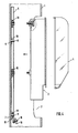
- the steel pole 1 shown has in the usual way a window opening 2 through which a valve block 3 with a transparent cover 4 in the illustrated embodiment, which can accommodate a number of cable connections and other electrical components in addition to fuses, can be installed and maintained.
- a standard C-rail 5 is provided which, according to the invention, is provided with an upper plug-in opening 6 and a lower plug-in opening 7, which is designed as a slot open at the front end, with the aid of which they are welded onto two bolts 8 and 9 welded into the steel tube mast at a distance can be plugged on.
- the actual jamming of the sliding nuts 15, 16 takes place in the mounting rail 5 with the end sections of the C-rail angled toward one another being jammed between the sliding nuts and the base of the valve block.
- the upper sliding nut 16 Due to the special design of the mounting of the mounting rail 5, the upper sliding nut 16 can not only be moved to the upper end of the mounting rail 5, but correspondingly long valve blocks can also be held on the rail, which in the area of the upper edge of the previously required Of course, opening 2 was not the case, the U-bars overlapping the rail at the front. In the case of very short valve blocks, the upper sliding nut is simply moved so that, like the lower sliding nut 15, it lies between the two bolts 8 and 9.
- the threaded hole for the grounding screw 18 can be arranged in the free section 19, which is also offset by an offset of about 45 ° offers simple possibility of actuation from the outside. This offset allows a screwdriver to be used very easily even if the earthing bracket should lie a good distance below the lower edge of the window opening 2.
Landscapes
- Engineering & Computer Science (AREA)
- Power Engineering (AREA)
- Forklifts And Lifting Vehicles (AREA)
- Elimination Of Static Electricity (AREA)
- Joining Of Building Structures In Genera (AREA)
Priority Applications (1)
| Application Number | Priority Date | Filing Date | Title |
|---|---|---|---|
| AT89110734T ATE95903T1 (de) | 1988-06-25 | 1989-06-14 | Stahlrohrmast mit einsteckbar befestigter tragschiene fuer einen armaturblock. |
Applications Claiming Priority (2)
| Application Number | Priority Date | Filing Date | Title |
|---|---|---|---|
| DE8808198U DE8808198U1 (de) | 1988-06-25 | 1988-06-25 | Stahlrohrmast mit einsteckbar befestigter Tragschiene für einen Armaturblock |
| DE8808198U | 1988-06-25 |
Publications (3)
| Publication Number | Publication Date |
|---|---|
| EP0348731A2 true EP0348731A2 (fr) | 1990-01-03 |
| EP0348731A3 EP0348731A3 (en) | 1990-05-16 |
| EP0348731B1 EP0348731B1 (fr) | 1993-10-13 |
Family
ID=6825363
Family Applications (1)
| Application Number | Title | Priority Date | Filing Date |
|---|---|---|---|
| EP89110734A Expired - Lifetime EP0348731B1 (fr) | 1988-06-25 | 1989-06-14 | Mât d'acier tubulaire avec rail de montage rapporté pour bloc de connexion |
Country Status (3)
| Country | Link |
|---|---|
| EP (1) | EP0348731B1 (fr) |
| AT (1) | ATE95903T1 (fr) |
| DE (2) | DE8808198U1 (fr) |
Families Citing this family (1)
| Publication number | Priority date | Publication date | Assignee | Title |
|---|---|---|---|---|
| FR3076666B1 (fr) * | 2018-01-08 | 2019-12-13 | Ludovic Lefebvre | Coffret electrique pour poteau d'eclairage, ensemble et procede de montage correspondant |
Family Cites Families (2)
| Publication number | Priority date | Publication date | Assignee | Title |
|---|---|---|---|---|
| BE717044A (fr) * | 1967-06-28 | 1968-12-02 | ||
| NL175361B (nl) * | 1981-06-26 | 1984-05-16 | Electrische Meetinstrumenten E | Veiligheidskast van kunststof voor montage in een metalen lichtmast of dergelijke. |
-
1988
- 1988-06-25 DE DE8808198U patent/DE8808198U1/de not_active Expired
-
1989
- 1989-06-14 EP EP89110734A patent/EP0348731B1/fr not_active Expired - Lifetime
- 1989-06-14 DE DE89110734T patent/DE58905884D1/de not_active Expired - Fee Related
- 1989-06-14 AT AT89110734T patent/ATE95903T1/de not_active IP Right Cessation
Also Published As
| Publication number | Publication date |
|---|---|
| DE8808198U1 (de) | 1988-08-25 |
| DE58905884D1 (de) | 1993-11-18 |
| ATE95903T1 (de) | 1993-10-15 |
| EP0348731A3 (en) | 1990-05-16 |
| EP0348731B1 (fr) | 1993-10-13 |
Similar Documents
| Publication | Publication Date | Title |
|---|---|---|
| DE9007599U1 (de) | Geräteträger | |
| WO2000036311A1 (fr) | Dispositif d'assemblage permettant de reunir une premiere piece a une seconde | |
| DE102020110550B4 (de) | Modulklemme, Verfahren zur Befestigung von Solarmodulen, Verbindungsanordnung zur Befestigung eines Solarmoduls und Anordnung mit Verbindungsanordnung und Solarmodul | |
| EP3241974B1 (fr) | Système pour un joint d'étanchéité, en particulier pour un joint de seuil ou pour un joint de sol s'abaissant automatiquement | |
| DE202015104250U1 (de) | Pfosten-Riegel-Verbindung | |
| DE2916003A1 (de) | Befestigungsvorrichtung, insbesondere fuer die verbindung von zwei bauteilen von bauwerken | |
| DE9105112U1 (de) | Halterungen für Kabel oder ähnliche langgestreckte Gegenstände | |
| EP0622575A2 (fr) | Dispositif de serrage utilisant un collier de fixation ou similaire pour tuyaux | |
| EP0348731B1 (fr) | Mât d'acier tubulaire avec rail de montage rapporté pour bloc de connexion | |
| AT408561B (de) | Schutzzaun | |
| DE29705621U1 (de) | Vorrichtung zum Befestigen eines Schirmdeckels | |
| DE1849271U (de) | Klemmelement zur befestigung elektrischer leitungsdraehte an elektrischen geraeten. | |
| DE8500148U1 (de) | Vorrichtung zum Potentialausgleich für Erdleiter von elektrischen Installationen | |
| DE2902759C2 (de) | Vorrichtung zur Befestigung von Rohrprofilen an tragenden Flächen | |
| DE19841314A1 (de) | Vorrichtung zum Verbinden von zwei Rohren | |
| DE19613167A1 (de) | Gerät zum Ausrichten einer Türzarge innerhalb einer Türöffnung einer Gebäudewand | |
| DE19636706C1 (de) | Befehls- oder Meldegerät | |
| AT405561B (de) | Plattenbefestigungselement | |
| DE490318C (de) | Isolatoren fuer Leuchtroehren | |
| CH368599A (de) | Versetzbare Glaszwischenwand | |
| DE1287174B (de) | Vorrichtung zur Befestigung eines stab- oder rohrfoermigen Laengstraegers einer Antenne an einem Standrohr | |
| DE1905829A1 (de) | Halterung zur Befestigung an hohlen,rohrfoermigen Traegern mit einem Schlitz auf einer ihrer Aussenflaechen | |
| DE2422695C3 (de) | Vorrichtung zum Befestigen einer einen AnschluBstutzen aufweisenden Mastleuchte | |
| DE104266C (fr) | ||
| EP3239537B1 (fr) | Dispositif de fixation et son procede de fabrication |
Legal Events
| Date | Code | Title | Description |
|---|---|---|---|
| PUAI | Public reference made under article 153(3) epc to a published international application that has entered the european phase |
Free format text: ORIGINAL CODE: 0009012 |
|
| AK | Designated contracting states |
Kind code of ref document: A2 Designated state(s): AT BE CH DE ES FR GB GR IT LI LU NL SE |
|
| PUAL | Search report despatched |
Free format text: ORIGINAL CODE: 0009013 |
|
| AK | Designated contracting states |
Kind code of ref document: A3 Designated state(s): AT BE CH DE ES FR GB GR IT LI LU NL SE |
|
| RAP1 | Party data changed (applicant data changed or rights of an application transferred) |
Owner name: PLFEIDERER VERKEHRSTECHNIK GMBH & CO. KG |
|
| RIN1 | Information on inventor provided before grant (corrected) |
Inventor name: WUCHERPFENNIG, KURT |
|
| 17P | Request for examination filed |
Effective date: 19901110 |
|
| 17Q | First examination report despatched |
Effective date: 19930216 |
|
| GRAA | (expected) grant |
Free format text: ORIGINAL CODE: 0009210 |
|
| AK | Designated contracting states |
Kind code of ref document: B1 Designated state(s): AT BE CH DE ES FR GB GR IT LI LU NL SE |
|
| PG25 | Lapsed in a contracting state [announced via postgrant information from national office to epo] |
Ref country code: IT Free format text: LAPSE BECAUSE OF FAILURE TO SUBMIT A TRANSLATION OF THE DESCRIPTION OR TO PAY THE FEE WITHIN THE PRESCRIBED TIME-LIMIT;WARNING: LAPSES OF ITALIAN PATENTS WITH EFFECTIVE DATE BEFORE 2007 MAY HAVE OCCURRED AT ANY TIME BEFORE 2007. THE CORRECT EFFECTIVE DATE MAY BE DIFFERENT FROM THE ONE RECORDED. Effective date: 19931013 Ref country code: GR Free format text: LAPSE BECAUSE OF FAILURE TO SUBMIT A TRANSLATION OF THE DESCRIPTION OR TO PAY THE FEE WITHIN THE PRESCRIBED TIME-LIMIT Effective date: 19931013 Ref country code: ES Free format text: THE PATENT HAS BEEN ANNULLED BY A DECISION OF A NATIONAL AUTHORITY Effective date: 19931013 Ref country code: SE Effective date: 19931013 Ref country code: NL Effective date: 19931013 Ref country code: GB Effective date: 19931013 Ref country code: FR Effective date: 19931013 Ref country code: BE Effective date: 19931013 |
|
| REF | Corresponds to: |
Ref document number: 95903 Country of ref document: AT Date of ref document: 19931015 Kind code of ref document: T |
|
| REF | Corresponds to: |
Ref document number: 58905884 Country of ref document: DE Date of ref document: 19931118 |
|
| EN | Fr: translation not filed | ||
| NLV1 | Nl: lapsed or annulled due to failure to fulfill the requirements of art. 29p and 29m of the patents act | ||
| GBV | Gb: ep patent (uk) treated as always having been void in accordance with gb section 77(7)/1977 [no translation filed] |
Effective date: 19931013 |
|
| PG25 | Lapsed in a contracting state [announced via postgrant information from national office to epo] |
Ref country code: AT Effective date: 19940614 |
|
| PG25 | Lapsed in a contracting state [announced via postgrant information from national office to epo] |
Ref country code: LU Free format text: LAPSE BECAUSE OF NON-PAYMENT OF DUE FEES Effective date: 19940630 Ref country code: CH Effective date: 19940630 Ref country code: LI Effective date: 19940630 |
|
| PLBE | No opposition filed within time limit |
Free format text: ORIGINAL CODE: 0009261 |
|
| STAA | Information on the status of an ep patent application or granted ep patent |
Free format text: STATUS: NO OPPOSITION FILED WITHIN TIME LIMIT |
|
| 26N | No opposition filed | ||
| REG | Reference to a national code |
Ref country code: CH Ref legal event code: PL |
|
| PGFP | Annual fee paid to national office [announced via postgrant information from national office to epo] |
Ref country code: DE Payment date: 19980625 Year of fee payment: 10 |
|
| PG25 | Lapsed in a contracting state [announced via postgrant information from national office to epo] |
Ref country code: DE Free format text: LAPSE BECAUSE OF NON-PAYMENT OF DUE FEES Effective date: 20000503 |