EP0348731A2 - Steel tube mast with affixed mounting rail for a connection block - Google Patents
Steel tube mast with affixed mounting rail for a connection block Download PDFInfo
- Publication number
- EP0348731A2 EP0348731A2 EP89110734A EP89110734A EP0348731A2 EP 0348731 A2 EP0348731 A2 EP 0348731A2 EP 89110734 A EP89110734 A EP 89110734A EP 89110734 A EP89110734 A EP 89110734A EP 0348731 A2 EP0348731 A2 EP 0348731A2
- Authority
- EP
- European Patent Office
- Prior art keywords
- rail
- mounting rail
- bracket
- opening
- earthing
- Prior art date
- Legal status (The legal status is an assumption and is not a legal conclusion. Google has not performed a legal analysis and makes no representation as to the accuracy of the status listed.)
- Granted
Links
Images

Classifications
-
- H—ELECTRICITY
- H02—GENERATION; CONVERSION OR DISTRIBUTION OF ELECTRIC POWER
- H02B—BOARDS, SUBSTATIONS OR SWITCHING ARRANGEMENTS FOR THE SUPPLY OR DISTRIBUTION OF ELECTRIC POWER
- H02B1/00—Frameworks, boards, panels, desks, casings; Details of substations or switching arrangements
- H02B1/015—Boards, panels, desks; Parts thereof or accessories therefor
- H02B1/04—Mounting thereon of switches or of other devices in general, the switch or device having, or being without, casing
Definitions
- the invention relates to a tubular steel mast with an opening for the assembly and maintenance of cable connections, fuses or the like, which are mounted as a valve block on an insertable on the inner wall opposite the opening, preferably designed as a standard C-rail via slide nuts , with a grounding bracket engaging in the lower end of the mounting rail.
- a Z-shaped angled earthing bracket is welded into the tubular steel mast with one leg in order to hold the lower end of the mounting rail.
- the upper end is held behind a welded-in U-bracket.
- the mounting rail is first pushed upwards through the upper U-bracket and then, when pulled down, pushed onto the end of the earthing bracket located in front of the inner wall.
- the first problem is that both the earthing bracket and the U-shaped upper bracket - to have a large space in between so that larger valve blocks can be used - should be as far apart as possible from each other than the longitudinal extent of the opening of the steel pipe masts.
- This type of assembly is even more cumbersome, since after galvanizing it is not necessary to bring the entire masts to the thread, which means considerable transport costs.
- there is also a limitation of the total length of the valve blocks to be used which in no way can be longer than the distance of the earthing bracket from the upper U-shaped retaining bracket, since it is only possible to move the slide nuts holding the valve block between them.
- the invention is therefore based on the object of designing a tubular steel mast of the type mentioned at the outset in such a way that it can be manufactured more easily and, at the same time, larger fitting blocks than previously can be used and maintained through a predetermined opening with simplified installation.
- the mounting rail is held on two bolts welded into the tube at a distance, the lower bolt simultaneously passing through the earthing strap inserted as a loose component into the rail, preferably in such a way that the mounting rail is attached to the them in recesses, one of which is designed as an elongated hole, is carried through the bolt-on clamping elements.
- the fastening according to the invention initially results in much simpler welding work, since the welding of a bolt which protrudes perpendicularly from the inner wall of the tubular steel mast is much easier than the welding of the grounding bracket and the U-shaped retaining bracket. This is all the more so since the bolts do not have to be arranged at the ends like the usual mounting parts, but can be arranged easily accessible at a distance from the upper and lower limits of the window opening of the tubular steel mast.
- the earthing bracket can be loose components in the construction according to the invention, which are only inserted with the assembly of the actual valve block after the bolts have been welded into the rail and are held together with this on the lower of the bolts, this also does not apply to the previous one Construction necessary re-cutting of threads after galvanizing the welded-in earthing bracket. The high transport costs previously incurred for this are completely eliminated.
- the clamping elements can be designed in a particularly simple manner as spring plate rings, which are simply placed on the bolts and, when pressed, clamp the rail against the inner wall of the tubular steel mast.
- the simultaneous clamping bracket of the earthing bracket, which is attached to the lower bolt together with the rail, does not require any special effort.
- an elongated hole Assumption - the provision of an elongated hole recess saves too exact positioning of the bolts relative to one another - to form through a slot open to the lower front end of the mounting rail. This not only enables the rail to be placed very easily on the bolts, but also makes it very easy to simultaneously insert and insert the earthing clip.
- mounting rails according to the invention can be mounted through a window in the tubular steel mast, which are much longer than the longer ones -Extension of the window opening, but at the same time the upper sliding nut is movable up to the upper end of the mounting rail, so that relatively large - at least much longer than before - valve blocks can be held on such a mounting rail.
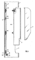
- the steel pole 1 shown has in the usual way a window opening 2 through which a valve block 3 with a transparent cover 4 in the illustrated embodiment, which can accommodate a number of cable connections and other electrical components in addition to fuses, can be installed and maintained.
- a standard C-rail 5 is provided which, according to the invention, is provided with an upper plug-in opening 6 and a lower plug-in opening 7, which is designed as a slot open at the front end, with the aid of which they are welded onto two bolts 8 and 9 welded into the steel tube mast at a distance can be plugged on.
- the actual jamming of the sliding nuts 15, 16 takes place in the mounting rail 5 with the end sections of the C-rail angled toward one another being jammed between the sliding nuts and the base of the valve block.
- the upper sliding nut 16 Due to the special design of the mounting of the mounting rail 5, the upper sliding nut 16 can not only be moved to the upper end of the mounting rail 5, but correspondingly long valve blocks can also be held on the rail, which in the area of the upper edge of the previously required Of course, opening 2 was not the case, the U-bars overlapping the rail at the front. In the case of very short valve blocks, the upper sliding nut is simply moved so that, like the lower sliding nut 15, it lies between the two bolts 8 and 9.
- the threaded hole for the grounding screw 18 can be arranged in the free section 19, which is also offset by an offset of about 45 ° offers simple possibility of actuation from the outside. This offset allows a screwdriver to be used very easily even if the earthing bracket should lie a good distance below the lower edge of the window opening 2.
Landscapes
- Engineering & Computer Science (AREA)
- Power Engineering (AREA)
- Forklifts And Lifting Vehicles (AREA)
- Elimination Of Static Electricity (AREA)
- Joining Of Building Structures In Genera (AREA)
Abstract
Stahlrohrmast mit einer Öffnung zur Montage und Wartung von Kabelanschlüssen, Sicherungen od.dgl., die als Armaturblock auf einer an der der Öffnung gegenüberliegenden Innenwand einsteckbar befestigten, vorzugsweise als Norm-C-Schiene ausgebildeten Tragschiene (5) über Schiebemuttern (15, 16) montiert sind, wobei ein Erdungsbügel (13) in das untere Tragschienenende eingreift, wobei die Tragschiene auf zwei beabstandet in das Rohr eingeschweißten Bolzen (8, 9) gehaltert ist, wobei der untere Bolzen (9) gleichzeitig den als loses Bauteil in die Schiene eingeschobenen Erdungsbügel (13) halternd durchsetzt. 
Description
Die Erfindung bezieht sich auf einen Stahlrohrmast mit einer Öffnung zur Montage und Wartung von Kabelanschlüssen, Sicherungen od.dgl., die als Armaturblock auf einer an der der Öffnung gegenüberliegenden Innenwand einsteckbar befestigten, vorzugsweise als Norm-C-Schiene ausgebildeten Tragschiene über Schiebemuttern montiert sind, wobei ein Erdungsbügel in das untere Tragschienenende eingreift.The invention relates to a tubular steel mast with an opening for the assembly and maintenance of cable connections, fuses or the like, which are mounted as a valve block on an insertable on the inner wall opposite the opening, preferably designed as a standard C-rail via slide nuts , with a grounding bracket engaging in the lower end of the mounting rail.
Bei den bislang üblichen Stahlrohrmasten mit angebauten Armaturen ist ein Z-förmig gewinkelter Erdungsbügel mit seinem einen Schenkel in den Stahlrohrmast eingeschweißt, um das untere Ende der Tragschiene haltend aufzunehmen. Das obere Ende ist hinter einem ebenfalls eingeschweißten U-Bügel gehaltert. Zur Befestigung wird zunächst die Tragschiene durch den oberen U-Bügel nach oben geschoben und dann beim Herunterziehen auf das vor der Innenwand liegende Ende des Erdungsbügels aufgesteckt. Diese Konstruktion bringt jedoch eine Reihe von erheblichen Fertigungs- und Montageschwierigkeiten mit sich.In the previously common tubular steel masts with attached fittings, a Z-shaped angled earthing bracket is welded into the tubular steel mast with one leg in order to hold the lower end of the mounting rail. The upper end is held behind a welded-in U-bracket. For fastening, the mounting rail is first pushed upwards through the upper U-bracket and then, when pulled down, pushed onto the end of the earthing bracket located in front of the inner wall. However, this construction brings with it a number of significant manufacturing and assembly difficulties.
Das erste Problem besteht darin, daß sowohl der Erdungsbügel als auch der U-förmige obere Haltebügel - um einen großen Platz dazwischen zu haben, so daß auch größere Armaturblöcke eingesetzt werden können - möglichst einen größeren Abstand voneinander aufweisen sollen als die Längserstreckung der Öffnung des Stahl rohrmastes. Dies erschwert aber das Einschweißen dieser Teile ganz erheblich. Noch wesentlich umständlicher ist diese Art der Montage, da es nach dem Verzinken nicht nochmals erforderlich ist, die ganzen Masten zum Nachschneiden der Gewinde zu bringen, was ganz erhebliche Transportkosten bedeutet. Schließlich ergibt sich aber auch eine Begrenzung der Gesamtlänge der einzusetzenden Armaturenblöcke, die keinesfalls länger sein können als der Abstand des Erdungsbügels vom oberen U-fömigen Haltebügel, da ja nur zwischen diesen eine Verschiebung der den Amaturenblock halternden Schiebemuttern möglich ist. Schließlich ist auch die Tatsache ungünstig, daß die Erdungsschraube senkrecht zur Rohrachse in den Erdungsbügel, der wegen seiner Halterungsfunktion für die C-Schiene nicht anders angeordnet sein kann, eingeschraubt werden muß, so daß entweder der Bügel im Bereich der Öffnung des Stahlrohrmastes liegen muß, was die Länge des Armaturenblocks noch weiter begrenzt, oder aber die Zugänglichkeit für einen Schraubendreher sehr schwierig und unhandlich ist.The first problem is that both the earthing bracket and the U-shaped upper bracket - to have a large space in between so that larger valve blocks can be used - should be as far apart as possible from each other than the longitudinal extent of the opening of the steel pipe masts. However, this makes welding these parts very difficult. This type of assembly is even more cumbersome, since after galvanizing it is not necessary to bring the entire masts to the thread, which means considerable transport costs. Finally, there is also a limitation of the total length of the valve blocks to be used, which in no way can be longer than the distance of the earthing bracket from the upper U-shaped retaining bracket, since it is only possible to move the slide nuts holding the valve block between them. Finally, the fact that the earthing screw must be screwed perpendicular to the tube axis into the earthing bracket, which cannot be arranged differently because of its mounting function for the C-rail, is also unfavorable, so that either the bracket must lie in the area of the opening of the tubular steel mast, which further limits the length of the valve block, or the accessibility for a screwdriver is very difficult and unwieldy.
Der Erfindung liegt daher die Aufgabe zugrunde, einen Stahlrohrmast der eingangs genannten Art so auszugestalten, daß er einfacher hergestellt werden kann und gleichzeitig bei vereinfachter Montage größere Armaturblöcke als bisher durch eine vorgegebene Öffnung eingesetzt und gewartet werden können.The invention is therefore based on the object of designing a tubular steel mast of the type mentioned at the outset in such a way that it can be manufactured more easily and, at the same time, larger fitting blocks than previously can be used and maintained through a predetermined opening with simplified installation.
Zur Lösung dieser Aufgabe ist erfindungsgemäß vorgesehen, daß die Tragschiene auf zwei beabstandet in das Rohr eingeschweißten Bolzen gehaltert ist, wobei der untere Bolzen gleichzeitig den als loses Bauteil in die Schiene eingeschobenen Erdungsbügel halternd durchsetzt, vorzugsweise in der Weise, daß die Tragschiene mittels auf die sie in Ausnehmungen, von denen eine als Langloch ausgebildet ist, durchsetzenden Bolzen aufgesteckten Klemmelementen gehaltert ist.To achieve this object, it is provided according to the invention that the mounting rail is held on two bolts welded into the tube at a distance, the lower bolt simultaneously passing through the earthing strap inserted as a loose component into the rail, preferably in such a way that the mounting rail is attached to the them in recesses, one of which is designed as an elongated hole, is carried through the bolt-on clamping elements.
Durch die erfindungsgemäße Befestigung ergeben sich zunächst von vorneherein wesentlich einfachere Schweißarbeiten, da das Aufschweißen eines senkrecht von der Innenwand des Stahlrohrmastes abstehenden Bolzens sehr viel einfacher ist als das Aufschweißen der Erdungsbügel und der U-fömigen Haltebügel. Dies gilt um so mehr, als die Bolzen ja nicht wie die bisher üblichen Montageteile an den Enden angeordnet sein müssen, sondern bequem zugänglich in Abstand von den oberen und unteren Begrenzungen der Fenster-Öffnung des Stahlrohrmastes angeordnet werden können. Dadurch, daß bei der erfindungsgemäßen Konstruktion die Erdungsbügel lose Bauteile sein können, die erst mit der Montage des eigentlichen Amaturenblocks nach dem Einschweißen der Bolzen in die Schiene eingeschoben werden und mit dieser gemeinsam auf dem unteren der Bolzen gehaltert werden, entfällt auch das bei der bisherigen Konstruktion notwendige Nachschneiden von Gewinden nach dem Verzinken des zunächst eingeschweißten Erdungsbügels. Die hierfür bisher angefallenen hohen Transportkosten entfallen also völlig.The fastening according to the invention initially results in much simpler welding work, since the welding of a bolt which protrudes perpendicularly from the inner wall of the tubular steel mast is much easier than the welding of the grounding bracket and the U-shaped retaining bracket. This is all the more so since the bolts do not have to be arranged at the ends like the usual mounting parts, but can be arranged easily accessible at a distance from the upper and lower limits of the window opening of the tubular steel mast. The fact that the earthing bracket can be loose components in the construction according to the invention, which are only inserted with the assembly of the actual valve block after the bolts have been welded into the rail and are held together with this on the lower of the bolts, this also does not apply to the previous one Construction necessary re-cutting of threads after galvanizing the welded-in earthing bracket. The high transport costs previously incurred for this are completely eliminated.
Die Klemmelemente können dabei in besonders einfacher Weise als Federblechringe ausgebildet sein, die einfach auf die Bolzen aufgesteckt werden und beim Andrükken die Schiene gegen die Innenwand des Stahlrohrmastes verklemmen. Die gleichzeitige Klemmhalterung auch des Erdungsbügels, der auf den unteren Bolzen zusammen mit der Schiene mit aufgesteckt wird, erfordert dabei überhaupt keinen gesonderten Aufwand.The clamping elements can be designed in a particularly simple manner as spring plate rings, which are simply placed on the bolts and, when pressed, clamp the rail against the inner wall of the tubular steel mast. The simultaneous clamping bracket of the earthing bracket, which is attached to the lower bolt together with the rail, does not require any special effort.
In Weiterbildung der Erfindung hat es sich dabei als besonders vorteilhaft erwiesen, eine Langlochaus nehmung - das Vorsehen einer Langlochausnehmung erspart allzu exakte Positionierungen der Bolzen zueinander - durch einen zum unteren Stirnende der Tragschiene offenen Schlitz zu bilden. Dies ermöglicht nicht nur ein sehr einfaches Aufsetzen der Schiene auf die Bolzen, sondern auch ein sehr einfaches gleichzeitiges Mitauf- und -einstecken des Erdungsbügels.In a further development of the invention, it has proven particularly advantageous to have an elongated hole Assumption - the provision of an elongated hole recess saves too exact positioning of the bolts relative to one another - to form through a slot open to the lower front end of the mounting rail. This not only enables the rail to be placed very easily on the bolts, but also makes it very easy to simultaneously insert and insert the earthing clip.
Durch die Anordnung eines der Bolzen am unteren Ende der Tragschiene, während der andere Bolzen relativ weit vom oberen Ende der Tragschiene entfernt angeordnet sein kann, lassen sich mit der erfindungsgemäßen Montage Tragschienen durch ein Fenster im Stahlrohrmast montieren, die sehr viel länger sind als die Längser-streckung der Fenster-Öffnung, wobei aber gleichzeitig die obere Schiebemutter bis zum oberen Ende der Tragschiene bewegbar ist, so daß relativ große - jedenfalls sehr viel längere als bisher - Armaturenblöcke auf einer solchen Tragschiene gehaltert werden können.By arranging one of the bolts at the lower end of the mounting rail, while the other bolt can be arranged relatively far from the upper end of the mounting rail, mounting rails according to the invention can be mounted through a window in the tubular steel mast, which are much longer than the longer ones -Extension of the window opening, but at the same time the upper sliding nut is movable up to the upper end of the mounting rail, so that relatively large - at least much longer than before - valve blocks can be held on such a mounting rail.
Schließlich liegt es auch noch im Rahmen der Erfindung, das freie Ende des Erdungsbügels mit der Gewindebohrung für die Erdungsschraube um ca. 45o gekröpft abzuwinkeln, so daß eine bequeme Betätigung der Erdungsschrauben auch dann möglich ist, wenn der Erdungsbügel unterhalb der Unterkante der Fensteröffnung liegt.Finally, it is also within the scope of the invention to angled the free end of the earthing bracket with the threaded hole for the earthing screw by approximately 45 o , so that the earthing screws can be actuated easily even when the earthing bracket is below the lower edge of the window opening .
Weitere Vorteile, Merkmale und Einzelheiten der Erfindung ergeben sich aus der nachfolgenden Beschreibung eines Ausführungsbeispiels sowie anhand der Zeichnung. Dabei zeigen:
- Fig. 1 eine Aufsicht auf den offenen Fenster-Öffnungsabschnitt eines Stahlrohrmasts mit eingesetztem, auf einer Tragschiene gehaltertem Amaturenblock,
- Fig. 2 eine vergrößerte perspektivische Explosionsdarstellung eines Ausschnitts des Stahlrohmasts zur Verdeutlichung der Tragschienenhalterung,
- Fig. 3 eine perspektivische Ansicht einer Schiebemutter,
- Fig. 4 einen vergrößerten Längsschnitt durch den Stahlrohrmast in einer Aufsetzstellung vor der Befestigung des Amaturenblocks.
- Fig. 1 is a plan view of the open window opening section of a tubular steel mast used dashboard mounted on a mounting rail,
- 2 is an enlarged perspective exploded view of a section of the steel pole to illustrate the mounting rail bracket,
- 3 is a perspective view of a sliding nut,
- Fig. 4 is an enlarged longitudinal section through the tubular steel mast in a mounting position before the attachment of the valve block.
Der gezeigte Stahlrohmast 1 weist in üblicher Weise eine Fenster-Öffnung 2 auf, durch welche ein Armaturenblock 3 mit einer im dargestellten Ausführungsbeispiel durchsichtigen Haube 4, der neben Sicherungen eine Reihe von Kabelanschlüssen und sonstigen elektrischen Bauteilen aufnehmen kann, montiert und gewartet werden kann. Zu diesem Zweck ist eine Norm-C-Schiene 5 vorgesehen, die erfindungsgemäß mit einer oberen Aufstecköffnung 6 und einer unteren, als zum Stirnende offener Schlitz ausgebildeten Aufstecköffnung 7 versehen ist, mit Hilfe deren sie auf zwei beabstandet in den Stahlrohrmast eingeschweißte Bolzen 8 und 9 aufgesteckt werden kann. Die eigentliche Halterung erfolgt dann durch Federklemmringe 10 bzw. 11, von denen der erstere die Schiene direkt gegen die Innenwand 12 des Stahlrohrmasts drückt, während der Federklemmring 11 auf den in das untere Ende der Tragschiene 5 eingeschobe nen Abschnitt 13 drückt, der durch eine auf den unteren Bolzen 9 aufsteckbare Bohrung 14 gemeinsam mit dem unteren Schienenende montiert werden kann. Bei 15 und 16 sind zwei an sich bekannte Schiebemuttern mit einem Klemmfederschenkel 17, der sie an jeder gewünschten Stelle der Schiene 5 festhält, bezeichnet, mit deren Hilfe (vergl. insbesondere Fig. 4) der Armaturenblock 3 an der Schiene angeschraubt wird. Mit dem Anschrauben erfolgt die eigentliche Verklemmung der Schiebemuttern 15, 16 in der Tragschiene 5 unter Einklemmung der aufeinander zugewinkelten Endabschnitte der C-Schiene zwischen den Schiebemuttern und dem Boden des Armaturenblocks. Durch die besondere Ausbildung der Halterung der Tragschiene 5 kann die obere Schiebemutter 16 nicht nur bis zum oberen Ende der Tragschiene 5 verschoben werden, sondern es können auch entsprechend lange Armaturenblöcke auf der Schiene gehaltert werden, was bei den bisher notwendigen, im Bereich der Oberkante der Öffnung 2 liegenden, die Schiene vorne übergreifenden U-Bügeln selbstverständlich nicht der Fall war. Bei sehr kurzen Armaturblöcken setzt man die obere Schiebemutter einfach um, so daß sie ebenso wie die untere Schiebemutter 15 zwischen den beiden Bolzen 8 und 9 liegt. Durch die erfindungsgemäße Ausbildung des Erdungsbügels als loses Bauteil, welches gemeinsam mit dem unteren Ende der Tragschiene 5 im Stahlrohrmast gehaltert werden kann, läßt sich die Gewindebohrung für die Erdungsschraube 18 im freien Abschnitt 19 anordnen, der darüber hinaus durch eine Kröpfung um etwa 45o die einfache Möglichkeit einer Betätigung von außen bietet. Ein Schraubendreher läßt sich durch diese Kröpfung auch dann noch sehr einfach ansetzen, wenn der Erdungsbügel ein ganzes Stück unterhalb der Unterkante der Fenster-Öffnung 2 liegen sollte.The steel pole 1 shown has in the usual way a window opening 2 through which a
Claims (4)
Priority Applications (1)
| Application Number | Priority Date | Filing Date | Title |
|---|---|---|---|
| AT89110734T ATE95903T1 (en) | 1988-06-25 | 1989-06-14 | STEEL PIPE MAST WITH INSERTABLE MOUNTING RAIL FOR AN INSTRUMENT BLOCK. |
Applications Claiming Priority (2)
| Application Number | Priority Date | Filing Date | Title |
|---|---|---|---|
| DE8808198U DE8808198U1 (en) | 1988-06-25 | 1988-06-25 | Tubular steel mast with insertable mounting rail for a fitting block |
| DE8808198U | 1988-06-25 |
Publications (3)
| Publication Number | Publication Date |
|---|---|
| EP0348731A2 true EP0348731A2 (en) | 1990-01-03 |
| EP0348731A3 EP0348731A3 (en) | 1990-05-16 |
| EP0348731B1 EP0348731B1 (en) | 1993-10-13 |
Family
ID=6825363
Family Applications (1)
| Application Number | Title | Priority Date | Filing Date |
|---|---|---|---|
| EP89110734A Expired - Lifetime EP0348731B1 (en) | 1988-06-25 | 1989-06-14 | Steel tube mast with affixed mounting rail for a connection block |
Country Status (3)
| Country | Link |
|---|---|
| EP (1) | EP0348731B1 (en) |
| AT (1) | ATE95903T1 (en) |
| DE (2) | DE8808198U1 (en) |
Families Citing this family (1)
| Publication number | Priority date | Publication date | Assignee | Title |
|---|---|---|---|---|
| FR3076666B1 (en) * | 2018-01-08 | 2019-12-13 | Ludovic Lefebvre | ELECTRICAL BOX FOR LIGHTING POST, ASSEMBLY AND ASSEMBLY METHOD THEREOF |
Family Cites Families (2)
| Publication number | Priority date | Publication date | Assignee | Title |
|---|---|---|---|---|
| BE717044A (en) * | 1967-06-28 | 1968-12-02 | ||
| NL175361B (en) * | 1981-06-26 | 1984-05-16 | Electrische Meetinstrumenten E | SAFETY CABINET OF PLASTIC FOR MOUNTING IN A METAL LIGHT POLE OR THE LIKE. |
-
1988
- 1988-06-25 DE DE8808198U patent/DE8808198U1/en not_active Expired
-
1989
- 1989-06-14 DE DE89110734T patent/DE58905884D1/en not_active Expired - Fee Related
- 1989-06-14 EP EP89110734A patent/EP0348731B1/en not_active Expired - Lifetime
- 1989-06-14 AT AT89110734T patent/ATE95903T1/en not_active IP Right Cessation
Also Published As
| Publication number | Publication date |
|---|---|
| DE8808198U1 (en) | 1988-08-25 |
| EP0348731A3 (en) | 1990-05-16 |
| EP0348731B1 (en) | 1993-10-13 |
| ATE95903T1 (en) | 1993-10-15 |
| DE58905884D1 (en) | 1993-11-18 |
Similar Documents
| Publication | Publication Date | Title |
|---|---|---|
| DE9007599U1 (en) | Equipment carrier | |
| WO2000036311A1 (en) | Coupling device for connecting a first workpiece to a second one | |
| DE102020110550B4 (en) | Module clamp, method for fastening solar modules, connection arrangement for fastening a solar module and arrangement with connection arrangement and solar module | |
| EP3241974B1 (en) | Assembly for a seal, in particular for a contact seal or for an automatically lowerable floor seal for doors | |
| DE202015104250U1 (en) | Post and rail connection | |
| DE2916003A1 (en) | Fixing device connecting two building components - has threaded rod held by one unit while another prevents motion of fixer in rail | |
| DE9105112U1 (en) | Holders for cables or similar elongated objects | |
| EP0622575A2 (en) | Mounting system using a pipe clamp or the like | |
| EP0348731B1 (en) | Steel tube mast with affixed mounting rail for a connection block | |
| AT408561B (en) | Protective fence | |
| DE29705621U1 (en) | Device for attaching an umbrella cover | |
| DE1849271U (en) | CLAMPING ELEMENT FOR FASTENING ELECTRICAL WIRING TO ELECTRICAL DEVICES. | |
| DE3420261A1 (en) | FASTENING CLAMP FOR CABLES AND PIPES WITH A LARGE DIAMETER RANGE | |
| DE8500148U1 (en) | Device for equipotential bonding for earth conductors in electrical installations | |
| DE2902759C2 (en) | Device for fastening pipe profiles to load-bearing surfaces | |
| DE19841314A1 (en) | Tube connector for connecting tubes used e.g. in stage construction connects the tube insides and has a lock on the top and bottom | |
| DE19613167A1 (en) | Equipment for aligning door frame in door opening in building | |
| DE19636706C1 (en) | Command or alarm device e.g pushbutton or indicator light | |
| AT405561B (en) | PANEL FASTENING ELEMENT | |
| DE490318C (en) | Insulators for light tubes | |
| CH368599A (en) | Movable glass partition | |
| DE1287174B (en) | Device for fastening a rod-shaped or tubular longitudinal beam of an antenna to a standpipe | |
| DE2422695C3 (en) | Device for fastening a mast light with a connecting piece | |
| DE104266C (en) | ||
| EP3239537B1 (en) | Fixing device and method for its manufacture |
Legal Events
| Date | Code | Title | Description |
|---|---|---|---|
| PUAI | Public reference made under article 153(3) epc to a published international application that has entered the european phase |
Free format text: ORIGINAL CODE: 0009012 |
|
| AK | Designated contracting states |
Kind code of ref document: A2 Designated state(s): AT BE CH DE ES FR GB GR IT LI LU NL SE |
|
| PUAL | Search report despatched |
Free format text: ORIGINAL CODE: 0009013 |
|
| AK | Designated contracting states |
Kind code of ref document: A3 Designated state(s): AT BE CH DE ES FR GB GR IT LI LU NL SE |
|
| RAP1 | Party data changed (applicant data changed or rights of an application transferred) |
Owner name: PLFEIDERER VERKEHRSTECHNIK GMBH & CO. KG |
|
| RIN1 | Information on inventor provided before grant (corrected) |
Inventor name: WUCHERPFENNIG, KURT |
|
| 17P | Request for examination filed |
Effective date: 19901110 |
|
| 17Q | First examination report despatched |
Effective date: 19930216 |
|
| GRAA | (expected) grant |
Free format text: ORIGINAL CODE: 0009210 |
|
| AK | Designated contracting states |
Kind code of ref document: B1 Designated state(s): AT BE CH DE ES FR GB GR IT LI LU NL SE |
|
| PG25 | Lapsed in a contracting state [announced via postgrant information from national office to epo] |
Ref country code: IT Free format text: LAPSE BECAUSE OF FAILURE TO SUBMIT A TRANSLATION OF THE DESCRIPTION OR TO PAY THE FEE WITHIN THE PRESCRIBED TIME-LIMIT;WARNING: LAPSES OF ITALIAN PATENTS WITH EFFECTIVE DATE BEFORE 2007 MAY HAVE OCCURRED AT ANY TIME BEFORE 2007. THE CORRECT EFFECTIVE DATE MAY BE DIFFERENT FROM THE ONE RECORDED. Effective date: 19931013 Ref country code: GR Free format text: LAPSE BECAUSE OF FAILURE TO SUBMIT A TRANSLATION OF THE DESCRIPTION OR TO PAY THE FEE WITHIN THE PRESCRIBED TIME-LIMIT Effective date: 19931013 Ref country code: ES Free format text: THE PATENT HAS BEEN ANNULLED BY A DECISION OF A NATIONAL AUTHORITY Effective date: 19931013 Ref country code: SE Effective date: 19931013 Ref country code: NL Effective date: 19931013 Ref country code: GB Effective date: 19931013 Ref country code: FR Effective date: 19931013 Ref country code: BE Effective date: 19931013 |
|
| REF | Corresponds to: |
Ref document number: 95903 Country of ref document: AT Date of ref document: 19931015 Kind code of ref document: T |
|
| REF | Corresponds to: |
Ref document number: 58905884 Country of ref document: DE Date of ref document: 19931118 |
|
| EN | Fr: translation not filed | ||
| NLV1 | Nl: lapsed or annulled due to failure to fulfill the requirements of art. 29p and 29m of the patents act | ||
| GBV | Gb: ep patent (uk) treated as always having been void in accordance with gb section 77(7)/1977 [no translation filed] |
Effective date: 19931013 |
|
| PG25 | Lapsed in a contracting state [announced via postgrant information from national office to epo] |
Ref country code: AT Effective date: 19940614 |
|
| PG25 | Lapsed in a contracting state [announced via postgrant information from national office to epo] |
Ref country code: LU Free format text: LAPSE BECAUSE OF NON-PAYMENT OF DUE FEES Effective date: 19940630 Ref country code: CH Effective date: 19940630 Ref country code: LI Effective date: 19940630 |
|
| PLBE | No opposition filed within time limit |
Free format text: ORIGINAL CODE: 0009261 |
|
| STAA | Information on the status of an ep patent application or granted ep patent |
Free format text: STATUS: NO OPPOSITION FILED WITHIN TIME LIMIT |
|
| 26N | No opposition filed | ||
| REG | Reference to a national code |
Ref country code: CH Ref legal event code: PL |
|
| PGFP | Annual fee paid to national office [announced via postgrant information from national office to epo] |
Ref country code: DE Payment date: 19980625 Year of fee payment: 10 |
|
| PG25 | Lapsed in a contracting state [announced via postgrant information from national office to epo] |
Ref country code: DE Free format text: LAPSE BECAUSE OF NON-PAYMENT OF DUE FEES Effective date: 20000503 |