EP0348660B1 - Positionsmesseinrichtung - Google Patents
Positionsmesseinrichtung Download PDFInfo
- Publication number
- EP0348660B1 EP0348660B1 EP89108991A EP89108991A EP0348660B1 EP 0348660 B1 EP0348660 B1 EP 0348660B1 EP 89108991 A EP89108991 A EP 89108991A EP 89108991 A EP89108991 A EP 89108991A EP 0348660 B1 EP0348660 B1 EP 0348660B1
- Authority
- EP
- European Patent Office
- Prior art keywords
- measuring device
- position measuring
- housing
- encapsulated
- carrier body
- Prior art date
- Legal status (The legal status is an assumption and is not a legal conclusion. Google has not performed a legal analysis and makes no representation as to the accuracy of the status listed.)
- Expired - Lifetime
Links
- 238000010438 heat treatment Methods 0.000 claims description 22
- 238000009833 condensation Methods 0.000 claims description 16
- 230000005494 condensation Effects 0.000 claims description 16
- 238000007789 sealing Methods 0.000 claims description 15
- 230000001105 regulatory effect Effects 0.000 claims description 7
- 239000004020 conductor Substances 0.000 claims description 5
- 239000002826 coolant Substances 0.000 claims description 4
- 239000000463 material Substances 0.000 claims description 4
- 238000001816 cooling Methods 0.000 claims description 3
- VYPSYNLAJGMNEJ-UHFFFAOYSA-N Silicium dioxide Chemical compound O=[Si]=O VYPSYNLAJGMNEJ-UHFFFAOYSA-N 0.000 claims description 2
- 229910052782 aluminium Inorganic materials 0.000 claims description 2
- XAGFODPZIPBFFR-UHFFFAOYSA-N aluminium Chemical compound [Al] XAGFODPZIPBFFR-UHFFFAOYSA-N 0.000 claims description 2
- 239000002775 capsule Substances 0.000 claims description 2
- 238000010276 construction Methods 0.000 claims description 2
- 239000000741 silica gel Substances 0.000 claims description 2
- 229910002027 silica gel Inorganic materials 0.000 claims description 2
- CURLTUGMZLYLDI-UHFFFAOYSA-N Carbon dioxide Chemical compound O=C=O CURLTUGMZLYLDI-UHFFFAOYSA-N 0.000 claims 2
- 239000004411 aluminium Substances 0.000 claims 1
- 229910002092 carbon dioxide Inorganic materials 0.000 claims 1
- 239000001569 carbon dioxide Substances 0.000 claims 1
- 238000005538 encapsulation Methods 0.000 claims 1
- 239000004033 plastic Substances 0.000 claims 1
- 229920003023 plastic Polymers 0.000 claims 1
- 230000000717 retained effect Effects 0.000 claims 1
- 238000009413 insulation Methods 0.000 description 11
- 230000001419 dependent effect Effects 0.000 description 5
- 239000010410 layer Substances 0.000 description 5
- 229920002430 Fibre-reinforced plastic Polymers 0.000 description 3
- 238000011109 contamination Methods 0.000 description 3
- 239000011151 fibre-reinforced plastic Substances 0.000 description 3
- 239000002244 precipitate Substances 0.000 description 3
- 238000012545 processing Methods 0.000 description 3
- 230000005540 biological transmission Effects 0.000 description 2
- 230000015572 biosynthetic process Effects 0.000 description 2
- 230000008859 change Effects 0.000 description 2
- 238000006073 displacement reaction Methods 0.000 description 2
- 230000000694 effects Effects 0.000 description 2
- 230000007613 environmental effect Effects 0.000 description 2
- 239000007788 liquid Substances 0.000 description 2
- 230000007257 malfunction Effects 0.000 description 2
- 238000004519 manufacturing process Methods 0.000 description 2
- 229910052751 metal Inorganic materials 0.000 description 2
- 239000002184 metal Substances 0.000 description 2
- 238000000034 method Methods 0.000 description 2
- 230000035515 penetration Effects 0.000 description 2
- VYZAMTAEIAYCRO-UHFFFAOYSA-N Chromium Chemical compound [Cr] VYZAMTAEIAYCRO-UHFFFAOYSA-N 0.000 description 1
- 239000012790 adhesive layer Substances 0.000 description 1
- 239000000919 ceramic Substances 0.000 description 1
- 229910052804 chromium Inorganic materials 0.000 description 1
- 239000011651 chromium Substances 0.000 description 1
- 238000012937 correction Methods 0.000 description 1
- 238000005520 cutting process Methods 0.000 description 1
- 230000007423 decrease Effects 0.000 description 1
- 238000013461 design Methods 0.000 description 1
- 239000011521 glass Substances 0.000 description 1
- 230000036039 immunity Effects 0.000 description 1
- 230000001939 inductive effect Effects 0.000 description 1
- 230000003993 interaction Effects 0.000 description 1
- 238000003754 machining Methods 0.000 description 1
- 238000005259 measurement Methods 0.000 description 1
- 238000001556 precipitation Methods 0.000 description 1
- 230000008569 process Effects 0.000 description 1
- 230000004044 response Effects 0.000 description 1
- 229920006395 saturated elastomer Polymers 0.000 description 1
- 238000012546 transfer Methods 0.000 description 1
- XLYOFNOQVPJJNP-UHFFFAOYSA-N water Substances O XLYOFNOQVPJJNP-UHFFFAOYSA-N 0.000 description 1
Images


Classifications
-
- G—PHYSICS
- G01—MEASURING; TESTING
- G01B—MEASURING LENGTH, THICKNESS OR SIMILAR LINEAR DIMENSIONS; MEASURING ANGLES; MEASURING AREAS; MEASURING IRREGULARITIES OF SURFACES OR CONTOURS
- G01B5/00—Measuring arrangements characterised by the use of mechanical techniques
- G01B5/0011—Arrangements for eliminating or compensation of measuring errors due to temperature or weight
- G01B5/0014—Arrangements for eliminating or compensation of measuring errors due to temperature or weight due to temperature
-
- G—PHYSICS
- G01—MEASURING; TESTING
- G01D—MEASURING NOT SPECIALLY ADAPTED FOR A SPECIFIC VARIABLE; ARRANGEMENTS FOR MEASURING TWO OR MORE VARIABLES NOT COVERED IN A SINGLE OTHER SUBCLASS; TARIFF METERING APPARATUS; MEASURING OR TESTING NOT OTHERWISE PROVIDED FOR
- G01D5/00—Mechanical means for transferring the output of a sensing member; Means for converting the output of a sensing member to another variable where the form or nature of the sensing member does not constrain the means for converting; Transducers not specially adapted for a specific variable
- G01D5/26—Mechanical means for transferring the output of a sensing member; Means for converting the output of a sensing member to another variable where the form or nature of the sensing member does not constrain the means for converting; Transducers not specially adapted for a specific variable characterised by optical transfer means, i.e. using infrared, visible, or ultraviolet light
- G01D5/32—Mechanical means for transferring the output of a sensing member; Means for converting the output of a sensing member to another variable where the form or nature of the sensing member does not constrain the means for converting; Transducers not specially adapted for a specific variable characterised by optical transfer means, i.e. using infrared, visible, or ultraviolet light with attenuation or whole or partial obturation of beams of light
- G01D5/34—Mechanical means for transferring the output of a sensing member; Means for converting the output of a sensing member to another variable where the form or nature of the sensing member does not constrain the means for converting; Transducers not specially adapted for a specific variable characterised by optical transfer means, i.e. using infrared, visible, or ultraviolet light with attenuation or whole or partial obturation of beams of light the beams of light being detected by photocells
- G01D5/347—Mechanical means for transferring the output of a sensing member; Means for converting the output of a sensing member to another variable where the form or nature of the sensing member does not constrain the means for converting; Transducers not specially adapted for a specific variable characterised by optical transfer means, i.e. using infrared, visible, or ultraviolet light with attenuation or whole or partial obturation of beams of light the beams of light being detected by photocells using displacement encoding scales
- G01D5/34746—Linear encoders
- G01D5/34761—Protection devices, e.g. caps; Blowing devices
-
- G—PHYSICS
- G01—MEASURING; TESTING
- G01D—MEASURING NOT SPECIALLY ADAPTED FOR A SPECIFIC VARIABLE; ARRANGEMENTS FOR MEASURING TWO OR MORE VARIABLES NOT COVERED IN A SINGLE OTHER SUBCLASS; TARIFF METERING APPARATUS; MEASURING OR TESTING NOT OTHERWISE PROVIDED FOR
- G01D2205/00—Indexing scheme relating to details of means for transferring or converting the output of a sensing member
- G01D2205/50—Grounding or electrostatically shielding a position sensor or encoder
Definitions
- the invention relates to a position measuring device according to the preamble of claim 1.
- Such position measuring devices can be designed as length or angle measuring devices which operate according to a wide variety of physical principles (DE-C-32 15 336 and DE-C-36 23 353).
- the position measuring devices are used on machines to determine the relative position of two or more machine components.
- position measuring devices are used in a humid environment - for example in so-called machining centers - there is a great risk even in the case of encapsulated position measuring devices that moisture vapors penetrate into the interior through the smallest leaks. In the event of temperature fluctuations, the vapors can condense and become uncontrolled precipitate so that temperature fluctuations can affect the function of the position measuring devices.
- the invention has for its object to provide a position measuring device with high interference immunity and high measuring accuracy.
- the advantages of the position measuring device according to the invention lie above all in that the temperature gradient between the measuring graduation support body and the scanning device on the one hand and the housing on the other hand condensate always precipitates on the colder housing, so that the sensitive measuring graduation and the scanning device remain free of precipitation.
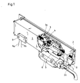
- a length measuring device 1 shown in FIG. 1 essentially consists of a light metal housing 2, in which a measuring graduation carrier body 3 is fastened in a known manner.
- the housing 2 is shown partially in section, so that a scanning device 4 is visible.
- the scanning device 4 also scans a measuring graduation 3a in a known manner, which is applied to the measuring graduation carrier body 3.
- the driver 5 extends through a longitudinal slot 2a in the housing 2, which is sealed by sealing lips 7 and 8 arranged in a roof-shaped manner.
- a machine in which the displacements between the machine bed and the slide are to be measured, carries the scanning device 4 on the machine bed via the mounting foot 6 and driver 5, and the housing 2 with the measuring graduation carrier body 3 on the slide.
- thermocouple 9 which is preferably designed as a Peltier element
- a cold pole is created on the housing 2, in the vicinity of which the condensate forms.
- the moisture is bound to the housing 2 in a targeted manner, so that no disturbing dew can form on the measuring graduation carrier body 3 and the scanning device 4.
- the Peltier element 9 is externally supplied with the necessary energy via connecting wires 9a and 9b.
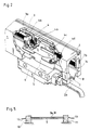
- FIG. 2 shows an enlarged section of the position measuring device 1, in which a temperature gradient between the components of the position measuring device 1 is generated in a different way.
- the same components or components with the same function are each provided with the same reference symbols in order to keep the number of reference symbols small and to make it easier to compare the individual exemplary embodiments.
- the housing 2 is not cooled here, but rather the components to be protected against condensation, such as the measuring graduation carrier body 3 and the scanning device 4, are heated slightly.
- heating lines 3b, 3c which are vapor-deposited on the carrier body 3 in addition to the measuring graduation 3a.
- the measuring graduation support body 3 consists of glass or ceramic. If the measuring division support body 3 made of electrically conductive material such as metal exists, an electrically insulating intermediate layer must be applied between it and the heating lines 3b, 3c, which, however, does not hinder the heat transfer from the heating lines 3b, 3c to the measuring graduation carrier body 3 if possible.
- the heating lines 3b, 3c are traversed by a current and can also be melted in the measuring body 3. A graphic representation of this variant has been omitted.
- the heating lines 3b, 3c can be supplied in a wide variety of ways. In FIG. 2, sliding contacts 4b, 4c, 4d are shown on the scanning device 4, via which a preferably regulated heating current is supplied to the heating lines 3b, 3c. Instead of the sliding contacts 4b, 4c, 4d, ball bearings can also be used for current transmission, which simultaneously guide the scanning device 4 on the measuring graduation carrier body 3. Inductive transmission of the heating current is also possible.
- FIG. 3 shows a solution for generating a temperature gradient in which the measuring graduation 3a itself is flowed through by current.
- the measuring graduation 3a consists, for example, of chromium and is evaporated onto its carrier body 3.
- the supply takes place via special feed lines 3d, 3e, which can be attached to the measuring division carrier body 3 in a similar manner as is known for heatable rear windows from the automotive industry.
- the heating current is to be regulated, it is advisable to vapor-deposit 3 temperature-dependent sensor resistances on the measuring graduation support body. This process, like the application of the heating cables, can already take place during the manufacture of the Measurement division take place. A graphic representation has been omitted.
- measuring graduation carrier body 3 When heating the measuring graduation carrier body 3, its dimensions naturally change. This effect can be considered in a variety of ways.
- One possibility is to manufacture the measuring graduation carrier body 3 to undersize so that it reaches its nominal size in the heated state. Furthermore, it is possible to adapt the expansion of the measuring graduation support body 3 to the temperature-related expansion of the machine on which the position measuring device 1 is attached by a corresponding heating control. This method can be designed in such a way that a non-linear error correction can be carried out by heating the measuring graduation carrier body 3 in different ways.
- a further possibility of mastering the temperature response caused by the heating is to clamp the measuring graduation carrier body 3 firmly on the machine with the aid of fastening elements 10 and 11 such that the machine-dependent dimensional changes are forced onto the measuring graduation carrier body 3 in such a way that the heating-related changes are not effective.
- This type of fastening of the measuring graduation carrier body 3 is shown in a very highly schematic manner in FIG. 5.
- the heating lines 3b, 3c can be supplied very advantageously by the fastening elements 10 and 11, which are connected via lines 12 and 13 to an energy source (not shown).
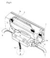
- FIG. 4 again takes up the alternative of keeping the housing 2 or a condensation cavity 14 connected to the housing 2 cooler than the measuring graduation carrier body 3 or the scanning device (not shown here).
- the condensation cavity 14 is connected to the interior of the housing 2. Since the same vapor pressure is accordingly present in both cavities, the moisture condenses in the condensation cavity 14, which exceeds the saturation in the cooler condensation cavity 14. As a result, there is a lower relative humidity inside the housing 2.
- a moisture exchanger should be provided in the condensation cavity 14, which can release the condensed moisture to drier outside air with the aid of its exchange surface.
- a moisture exchanger can be a wick 15, which is permeable to moisture but largely impermeable to air.
- the drop shape in the dash-dotted circle has been selected in FIG. However, this representation does not mean that the moisture will drip off, rather it will evaporate.
- the condensation cavity 14 can be cooled by various measures.
- coolant indicated by arrows flows from the coolant circuit of the machine through the condensation cavity 14.
- all coolants can be used for cooling (CO2 snow and the like).
- the condensate can be chemically or physically bound using exchangeable elements (silica gel capsules).
- a length measuring device 1 shown in FIG. 6 consists of an inner housing 2, in which a measuring graduation carrier body 3 is fastened in a known manner.
- the inner housing 2 is shown in section so that a scanning device 4 is visible.
- the scanning device 4 also scans a measuring graduation (not shown), which is applied to the measuring graduation carrier body 3, in a likewise known manner.
- the driver 5 extends through a longitudinal slot 2a in the inner housing 2, which is sealed by V-shaped sealing lips 7 and 8.
- An outer housing 9 encloses the inner housing 2, which is fastened in the interior of the outer housing 9 via holding elements 2b, 2c, 2d, 2e. Further sealing lips 10 and 11 close a longitudinal slot 9a of the outer housing 9. These sealing lips 10 and 11 are also arranged in a V-shape and are also penetrated by the driver 5.
- the arrangement of the sealing lips 7, 8 and 10, 11 is often described as roof-shaped - this designation and consideration is of course dependent on the mounting position of the position measuring device 1.
- the two housings 2 and 9 are made of different materials whose thermal conductivity coefficients differ from one another as much as possible.
- the housing 2 should have the smallest possible heat conductivity and the housing 9 the largest possible.
- the inner housing 2 consists of fiber-reinforced plastic and the outer housing 9 made of aluminum.
- a machine not shown, in which the displacements between the machine bed and the slide are to be measured, carries the scanning device 4 on the machine bed via the mounting foot 6 and driver 5, and the housing 2 and 9 on the slide with the measuring graduation carrier body 3.
- the risk of fogging of the measuring graduation carrier body 3 and the scanning device 4 is very greatly reduced.
- the inside surfaces of the outside housing 9 will very quickly assume the low outside temperature due to the high thermal conductivity.
- the air then cools between the outer housing 9 and the inner housing 2, the moisture in the then oversaturated air condenses on the inner surfaces of the outer housing 9 and then flows outwards.
- openings 12 are provided in suitable locations in the outer housing 9. A vapor pressure gradient arises between the interior of the inner housing 2 and the space between the housings 2 and 9, but this is compensated for again via small openings 13 in the inner housing 2.
- the vapor content in the inner housing 2 decreases faster than the temperature, so that no supersaturated air can arise in the interior of the inner housing 2, which could lead to fogging of the measuring graduation carrier body 3 and / or scanning device 4.
- the double sealing lips 7, 8 and 10, 11 ensure good mechanical protection against environmental influences, which also acts against splash water.
- the holding elements 2b, 2c, 2d, 2f are designed so that the inner housing 2 can be inserted into the outer housing 9, but cannot change its position there easily.
- the holding elements and their receiving channels are interrupted along the housing in order not to hinder the discharge of the condensate.
- FIG. 7 shows a variant of the position measuring device 1 according to FIG. 6. Reference symbols are only used if there are deviations from FIG. 6.
- an inner housing 22 has a longitudinal slot 22a, the position of which is rotated by approximately 90 ° relative to a longitudinal slot 29a in an outer housing 29.
- the longitudinal slots 22a and 29a are sealed with sealing lips 27, 28 and 210, 211.
- a driver 25, which connects a scanning device 24 to a mounting element 26, is cranked several times in order to be able to reach through the longitudinal slots 22a and 29a.
- the inner housing 22 is supported on projections 22b and 22c on inner surfaces of the outer housing 29 and can be adjusted within certain limits by means of adjusting screws 22d and 22e. Openings 213 are provided for vapor pressure compensation.
- openings 13 and 213 for vapor pressure compensation can also be provided.
- one or both end pieces on the inner housings 2 or 22 can be omitted.
- An aligned arrangement is to be understood here to mean that the longitudinal slots lie one behind the other on a straight line in the direction from the mounting element to the scanning device, which is illustrated by the illustration in FIG.
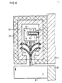
- FIG. 8 shows an encapsulated length measuring device in cross section, in which a carrier body T1 with a measuring graduation M1 is fastened inside a housing G1 closed on all sides in the form of a hollow profile on a web S1 by means of an adhesive layer K1.
- the measuring graduation M1 is scanned in a known manner, for example photoelectrically, by a scanning unit A1.
- the housing G1 has a longitudinal slot L1, which is closed by two roof-shaped inclined flexible sealing lip pairs D1a, D1b, through which a driver N1 projects in the form of a double-sided sword, which connects the scanning unit A1 to a mounting foot F1.
- the housing G1 is encased on all sides except for the area of the longitudinal slot L1 by a thermal insulation unit E1 in the form of an outer insulation layer and on a carriage X1 of a processing machine, not shown, for example at its two ends by means of fastening brackets - as in DE-C-25 05 585 described - attached.
- the mounting foot F1 is connected in any way to the bed B1 of the processing machine; the carriage X1 and the bed B1 represent the two objects whose relative position is to be measured.
- thermal insulation unit E1 By providing the thermal insulation unit E1, temperature drops in the immediate vicinity of the position measuring device cannot reach into the interior of the housing G1, so that there is a temperature gradient between the measuring graduation M1 and the scanning unit A1 inside the housing G1 and the immediate surroundings outside the housing G1 . Since the temperature inside the housing G1 is largely maintained in the event of temperature fluctuations in the environment, there is no annoying condensate formation of the moisture vapors inside the housing G1.
- the driver N1 consists of a material with very low thermal conductivity, for example of a fiber-reinforced plastic; Furthermore, in addition to the outer pair of sealing lips D1a, an inner pair of sealing lips D1b is provided, which furthermore reduces the penetration of moisture vapors into the interior of the housing G1.
- the thermal insulation unit E1 can also be designed as an inner insulation layer on the inner surfaces of the housing G1 in order to rule out thermal interactions between the interior of the housing G1 and the surroundings.
- the housing G1 itself can also form the thermal insulation unit E1 from heat-insulating fiber-reinforced plastic.
- FIG. 9 shows an encapsulated length measuring device in cross section, which has the same components as the length measuring device according to FIG. 8 and thus also the same reference numerals, however the number 1 is replaced by the number 2.
- the housing G2 is inserted in thermal contact into a trough-like temperature control unit E2, which in turn is fastened in any way to the carriage X2 of the processing machine.
- This temperature control unit E2 consists of a U-shaped central part MT, the bottom and walls of which are provided with longitudinally extending holes C and which is delimited at both ends by plate-shaped end parts ETa, ETb, each of which has a collecting hole SBa, SBb for the holes C des Middle part MT have.
- the collecting hole SBa is charged with a temperature-controlled liquid which, after flowing through the holes C of the middle part MT, emerges again from the collecting hole SBb of the other end part ETb (FIG. 10).
- temperature drops in the immediate vicinity of the position measuring device can also not in the Pass through the interior of the housing G2, so that there is a temperature gradient between the measuring graduation M2 and the scanning unit A2 inside the housing G2 and the immediate surroundings outside the housing G2. Since the temperature inside the housing G2 remains constant with temperature fluctuations in the environment, there is no annoying condensate formation of the moisture vapors inside the housing G2.
- the center piece MT can also consist of several individual pieces MTa, MTb, MTc ..., in particular with different grid lengths, which can be easily adapted to position measuring devices of different lengths.
- the temperature control unit can simultaneously form the housing for the measuring graduation and the scanning unit.
- the bores C of the central part MT or the individual pieces MTa, MTb, MTc can also be flowed through in alternating directions, the end parts ETa, ETb each having two collecting bores SBa, SBb for the inflow and outflow of the liquid.
- the thermal insulation unit E1 can also consist of individual pieces, which in particular have different grid lengths; Furthermore, the insulation unit E1 can also consist of an inner insulation layer and an outer insulation layer.
- the invention can be used for so-called open as well as in encapsulated position measuring devices that work according to a wide variety of physical measuring principles.
Landscapes
- Physics & Mathematics (AREA)
- General Physics & Mathematics (AREA)
- Length Measuring Devices With Unspecified Measuring Means (AREA)
- Transmission And Conversion Of Sensor Element Output (AREA)
- Optical Transform (AREA)
- Length Measuring Devices By Optical Means (AREA)
Description
- Die Erfindung bezieht sich auf eine Positionsmeßeinrichtung gemäß dem Oberbegriff des Anspruches 1.
- Derartige Positionsmeßeinrichtungen können als Längen- oder Winkelmeßeinrichtungen ausgeführt sein, die nach den verschiedensten physikalischen Prinzipien arbeiten (DE-C- 32 15 336 und DE-C- 36 23 353).
- Die Positionsmeßeinrichtungen werden an Maschinen eingesetzt, um die Relativlage zweier oder mehrerer Maschinen-Bauteile zu bestimmen.
- Wenn die Positionsmeßeinrichtungen in feuchter Umgebung - beispielsweise in sogenannten Bearbeitungszentren - eingesetzt werden, ist auch bei gekapselten Positionsmeßeinrichtungen die Gefahr groß, daß durch kleinste Lecks Feuchtigkeitsdämpfe ins Innere eindringen. Bei Temperaturschwankungen können die Dämpfe kondensieren und sich unkontrolliert niederschlagen, so daß Temperaturschwankungen die Funktion der Positionsmeßeinrichtungen beeinflussen können.
- Der Erfindung liegt die Aufgabe zugrunde, eine Positionsmeßeinrichtung mit hoher Störsicherheit und hoher Meßgenauigkeit zu schaffen.
- Diese Aufgabe wird von einer Positionsmeßeinrichtung mit den Merkmalen des Anspruches 1 gelöst.
- Vorteilhafte Ausgestaltungsmöglichkeiten sind in den abhängigen Ansprüchen angegeben.
- Die Vorteile der erfindungsgemäßen Positionsmeßeinrichtung liegen vor allem darin, daß sich durch das Temperaturgefälle zwischen dem Meßteilungs-Trägerkörper und der Abtasteinrichtung einerseits und dem Gehäuse andererseits Kondensat immer am kälteren Gehäuse niederschlägt, so daß die empfindliche Meßteilung und die Abtasteinrichtung frei von Niederschlägen bleiben.
- Welche der vielfältigen Möglichkeiten, die durch die abhängigen Ansprüche aufgezeigt werden, der Fachmann letztendlich realisiert, hängt vom Anwendungsfall ab.
- Anhand von Ausführungsbeispielen soll die Erfindung nachstehend mit Hilfe der Zeichnungen noch näher erläutert werden.
- Es zeigen
- Figur 1 eine Längenmeßeinrichtung mit einem Thermoelement;
- Figur 2 einen vergrößerten Abschnitt mit Heizleitungen am Meßteilungs-Trägerkörper;
- Figur 3 eine Längenmeßeinrichtung mit einer Meßteilung als Heizelement;
- Figur 4 eine Längenmeßeinrichtung mit einem Kondensationshohlraum;
- Figur 5 einen festeingespannten Meßteilungs-Trägerkörper;
- Figur 6 eine Längenmeßeinrichtung mit einem Doppelgehäuse im Querschnitt;
- Figur 7 eine Variante der Meßeinrichtung gemäß Figur 4;
- Figur 8 eine gekapselte Längenmeßeinrichtung mit einer Isoliereinheit im Querschnitt;
- Figur 9 eine gekapselte Längenmeßeinrichtung mit einer Temperiereinheit im Querschnitt und
- Figur 10 die Temperiereinheit in der Seitenansicht.
- Eine in Figur 1 dargestellte Längenmeßeinrichtung 1 besteht im wesentlichen aus einem Leichtmetall-Gehäuse 2, in dem ein Meßteilungs-Trägerkörper 3 in bekannter Weise befestigt ist. Das Gehäuse 2 ist teilweise geschnitten dargestellt, so daß eine Abtasteinrichtung 4 sichtbar wird. Die Abtasteinrichtung 4 tastet in ebenfalls bekannter Weise photo-elektrisch eine Meßteilung 3a ab, die auf dem Meßteilungs-Trägerkörper 3 aufgebracht ist. Ein Mitnehmer 5, der den Querschnitt eines zweiseitigen Schwertes hat, verbindet die Abtasteinrichtung 4 mit einem Montagefuß 6. Der Mitnehmer 5 durchragt einen Längsschlitz 2a im Gehäuse 2, der durch dachförmig angeordnete Dichtlippen 7 und 8 abgedichtet ist.
- Eine nicht dargestellte Maschine, bei der die Verschiebungen zwischen Maschinenbett und Schlitten gemessen werden sollen, trägt am Maschinenbett über Montagefuß 6 und Mitnehmer 5 die Abtasteinrichtung 4 und am Schlitten das Gehäuse 2 mit dem Meßteilungs-Trägerkörper 3.
- Wie eingangs beschrieben, dringt durch feinste Lecks Feuchtigkeit in den Innenraum des im wesentlichen allseitig geschlossenen Gehäuses 2 ein. Durch Temperaturschwankungen in der Umgebung der Positionsmeßeinrichtung 1 kann dieser Feuchtigkeitsdampf kondensieren und sich am MeßteilungsTrägerkörper 3 oder an der Abtasteinrichtung 4 unkontrolliert niederschlagen. Das Kondensat stellt eine Verschmutzung der für die Funktion der Positionsmeßeinrichtung 1 wesentlichen Bauteile dar und führt deshalb zu Störungen.
- Mit Hilfe eines Thermoelementes 9, das bevorzugt als Peltierelement ausgebildet ist, wird am Gehäuse 2 ein Kältepol geschaffen, in dessen Nähe sich das Kondensat bildet. Dadurch wird die Feuchtigkeit am Gehäuse 2 gezielt gebunden, so daß sich an dem Meßteilungs-Trägerkörper 3 und der Abtasteinrichtung 4 kein störender Tau bilden kann.
- Das Peltierelement 9 wird über Anschlußdrähte 9a und 9b extern mit der nötigen Energie versorgt.
- In Figur 2 ist ein vergrößerter Abschnitt der Positionsmeßeinrichtung 1 dargestellt, bei der auf andere Weise ein Temperaturgefälle zwischen den Bauteilen der Positionsmeßeinrichtung 1 erzeugt wird.
- Bei diesem und den folgenden Ausführungsbeispielen sind gleiche Bauteile oder Bauteile mit gleicher Funktion mit jeweils denselben Bezugszeichen versehen, um die Anzahl der Bezugszeichen gering zu halten und die Gegenüberstellung der einzelnen Ausführungsbeispiele zu erleichtern.
- Im Gegensatz zum Ausführungsbeispiel gemäß Figur 1 wird hier nicht das Gehäuse 2 gekühlt, sondern die vor Betauung zu schützenden Bauelemente wie Meßteilungs-Trägerköper 3 und Abtasteinrichtung 4 werden gering erhitzt.
- Dies geschieht über Heizleitungen 3b, 3c, die zusätzlich zur Meßteilung 3a auf dem Trägerkörper 3 aufgedampft sind. Dabei wird davon ausgegangen, daß der Meßteilungs-Trägerkörper 3 aus Glas oder Keramik besteht. Wenn der Meßteilungs-Trägerkörper 3 aus elektrisch leitendem Material wie Metall besteht, muß zwischen ihm und den Heizleitungen 3b, 3c eine elektrisch isolierende Zwischenschicht angebracht werden, die jedoch den Wärmeübergang von den Heizleitungen 3b, 3c auf den Meßteilungs-Trägerkörper 3 möglichst nicht behindert.
- Die Heizleitungen 3b, 3c werden von einem Strom durchflossen und können auch im Meßteilungs-Trägerkörper 3 eingeschmolzen sein. Auf eine bildliche Darstellung dieser Variante wurde verzichtet. Die Speisung der Heizleitungen 3b, 3c kann auf die unterschiedlichsten Weisen erfolgen. In Figur 2 sind an der Abtasteinrichtung 4 Schleifkontakte 4b, 4c, 4d gezeigt, über die ein vorzugsweise geregelter Heizstrom den Heizleitungen 3b, 3c zugeführt wird. Anstelle der Schleifkontakte 4b, 4c, 4d können auch Kugellager zur Stromübertragung benutzt werden, die gleichzeitig die Abtasteinrichtung 4 an dem Meßteilungs-Trägerkörper 3 führen. Auch eine induktive Übertragung des Heizstromes ist möglich.
- Figur 3 zeigt eine Lösung zum Erzeugen eines Temperaturgefälles, bei der die Meßteilung 3a selbst von Strom durchflossen wird. Die Meßteilung 3a besteht beispielsweise aus Chrom und ist auf ihren Trägerkörper 3 aufgedampft. Die Speisung erfolgt über besondere Zuleitungen 3d, 3e, die am Meßteilungs-Trägerkörper 3 in ähnlicher Weise befestigt werden können, wie bei heizbaren Heckscheiben aus dem Automobilbau bekannt ist.
- Wenn der Heizstrom geregelt werden soll, ist es sinnvoll, auf dem Meßteilungs-Trägerkörper 3 temperaturabhängige Fühlerwiderstände aufzudampfen. Dieser Vorgang kann, ebenso wie das Aufbringen der Heizleitungen, bereits bei der Herstellung der Meßteilung erfolgen. Auf eine zeichnerische Darstellung wurde verzichtet.
- Beim Heizen des Meßteilungs-Trägerkörpers 3 verändern sich naturgemäß seine Abmessungen. Dieser Effekt kann in vielfältiger Weise berücksichtigt werden. Eine Möglichkeit besteht darin, den Meßteilungs-Trägerkörper 3 auf Untermaß zu fertigen, so daß er im beheizten Zustand sein Sollmaß erreicht. Ferner ist es möglich, durch eine entsprechende Heizungsregelung die Ausdehnung des Meßteilungs-Trägerkörpers 3 der temperaturbedingten Ausdehnung der Maschine anzupassen, an der die Positionsmeßeinrichtung 1 angebaut ist. Diese Methode läßt sich so ausgestalten, daß durch partiell unterschiedliche Erwärmung des Meßteilungs-Trägerkörpers 3 eine nichtlineare Fehlerkorrektur vorgenommen werden kann.
- Eine weitere Möglichkeit, den durch das Heizen bedingten Temperaturgang meßtechnisch zu beherrschen, besteht darin, den Meßteilungs-Trägerkörper 3 mit Hilfe von Befestigungselementen 10 und 11 derart an der Maschine fest einzuspannen, daß die maschinen-abhängigen Abmessungsänderungen dem Meßteilungs-Trägerkörper 3 derart aufgezwungen werden, daß die heizungsbedingten Änderungen nicht zur Wirkung kommen. Diese Art der Befestigung des Meßteilungs-Trägerkörpers 3 ist sehr stark schematisiert in Figur 5 gezeigt. In sehr vorteilhafter Weise kann bei dieser Befestigungsart die Speisung der Heizleitungen 3b, 3c durch die Befestigungselemente 10 und 11 erfolgen, die über Zuleitungen 12 und 13 mit einer nicht dargestellten Energiequelle verbunden sind.
- In Figur 4 ist nochmals die Alternative aufgegriffen, das Gehäuse 2 bzw. einen mit dem Gehäuse 2 verbundenen Kondensations-Hohlraum 14 kühler zu halten als den Meßteilungs-Trägerkörper 3 bzw. die hier nicht dargestellte Abtasteinrichtung. Der Kondensations-Hohlraum 14 ist mit dem Inneren des Gehäuses 2 verbunden. Da in beiden Hohlräumen demgemäß derselbe Dampfdruck vorhanden ist, kondensiert im Kondensations-Hohlraum 14 die Feuchtigkeit, die die Sättigung im kühleren Kondensations-Hohlraum 14 übersteigt. Dadurch herrscht im Inneren des Gehäuses 2 eine geringere relative Feuchte.
- Im Kondensations-Hohlraum 14 sollte ein Feuchtetauscher vorgesehen sein, der mit Hilfe seiner Austauschfläche die kondensierte Feuchte an trockenere Außenluft abgeben kann. Ein solcher Feuchtetauscher kann ein Docht 15 sein, der feuchtedurchlässig aber weitgehend luftundurchlässig ist. Um die Abgabe der kondensierten Feuchte an die Außenluft mittels Docht zu versinnbildlichen, ist in der Figur 4 die Tropfenform im strichpunktierten Kreis gewählt worden. Diese Darstellung bedeutet aber nicht, daß die Feuchtigkeit abtropfen wird, vielmehr wird sie verdunsten.
- Die Kühlung des Kondensations-Hohlraumes 14 kann durch unterschiedliche Maßnahmen erfolgen. Im gezeigten Beispiel fließt durch Pfeile angedeutete Kühlflüssigkeit aus dem Kühlmittelkreislauf der Maschine durch den Kondensations-Hohlraum 14.
- Analog zu Figur 1 ist aber auch eine Kühlung durch Peltierelemente möglich.
- Zur Kühlung sind im Grunde alle Kühlmittel verwendbar (CO₂-Schnee u. dgl.).
- Wenn ein Kondensations-Hohlraum 14, wie er in Figur 4 mit einer Positionsmeßeinrichtung 1 dargestellt ist, mit mehreren Positionsmeßeinrichtungen verbunden ist, kann der bauliche Aufwand erheblich verringert werden.
- Außer durch Feuchtetauscher kann das Kondensat durch austauschbare Elemente chemisch oder physikalisch gebunden werden (Silicagel-Kapseln).
- Eine in Figur 6 dargestellte Längenmeßeinrichtung 1 besteht aus einem Innengehäuse 2, in dem ein Meßteilungs-Trägerkörper 3 in bekannter Weise befestigt ist. Das Innengehäuse 2 ist geschnitten dargestellt, so daß eine Abtasteinrichtung 4 sichtbar wird. Die Abtasteinrichtung 4 tastet in ebenfalls bekannter Weise photoelektrisch eine Meßteilung (nicht dargestellt) ab, die auf dem Meßteilungs-Trägerkörper 3 aufgebracht ist. Ein Mitnehmer 5, der den Querschnitt eines zweiseitigen Schwertes hat, verbindet die Abtasteinrichtung 4 mit einem Montagefuß 6. Der Mitnehmer 5 durchragt einen Längsschlitz 2a im Innengehäuse 2, der durch V-förmig angeordnete Dichtlippen 7 und 8 abgedichtet ist.
- Ein Außengehäuse 9 umschließt das Innengehäuse 2, welches über Halteelemente 2b, 2c, 2d, 2e im Innenraum des Außengehäuses 9 befestigt ist. Weitere Dichtlippen 10 und 11 schließen einen Längsschlitz 9a des Außengehäuses 9 ab. Diese Dichtlippen 10 und 11 sind ebenfalls V-förmig angeordnet und werden ebenfalls vom Mitnehmer 5 durchragt.
- Oftmals wird die Anordnung der Dichtlippen 7, 8 und 10,11 als dachförmig beschrieben - diese Bezeichnungs- und Betrachtungsweise ist natürlich von der Anbaulage der Positionsmeßeinrichtung 1 abhängig.
- Gemäß der Erfindung sind die beiden Gehäuse 2 und 9 aus verschiedenen Materialien, deren Wärmeleitkoeffizienten sich möglichst stark voneinander unterscheiden. So soll das Gehäuse 2 einen möglichst kleinen und das Gehäuse 9 einen möglichst großen Wärmeleitkoeffizienten haben. Aus diesem Grund besteht das Innengehäuse 2 aus faserverstärktem Kunststoff und das Außengehäuse 9 aus Aluminium.
- Eine nicht dargestellte Maschine, bei der die Verschiebungen zwischen Maschinenbett und Schlitten gemessen werden sollen, trägt am Maschinenbett über Montagefuß 6 und Mitnehmer 5 die Abtasteinrichtung 4 und am Schlitten die Gehäuse 2 und 9 mit dem Meßteilungs-Trägerkörper 3.
- Wie eingangs beschrieben, dringt durch feinste Lecks Feuchtigkeit in den Innenraum der im wesentlichen allseitig geschlossenen Positionsmeßeinrichtung 1 ein. Durch Temperaturschwankungen in der Umgebung der Positiosmeßeinrichtung 1 kann dieser Feuchtigkeitsdampf kondensieren und sich am Meßteilungs-Trägerkörper 3 oder an der Abtasteinrichtung 4 unkontrolliert niederschlagen. Das Kondensat stellt eine Verschmutzung der für die Funktion der Positionsmeßeinrichtung 1 wesentlichen Bauteile dar und führt deshalb zu Störungen.
- Mit dem Doppelgehäuse gemäß der Erfindung wird die Gefahr des Beschlagens von Meßteilungs-Trägerkörper 3 und Abtasteinrichtung 4 sehr stark herabgesetzt.
- Sinkt beispielsweise die Außentemperatur in der Umgebung der Positionsmeßeinrichtung 1 bei nahezu gesättigter Luft im Geräteinneren ab, dann werden die Innenflächen des Außengehäuses 9 wegen der hohen Wärmeleitfähigkeit sehr schnell die niedrige Außentemperatur annehmen. Anschließend kühlt die Luft zwischen dem Außengehäuse 9 und dem Innengehäuse 2 ab, die Feuchte der dann übersättigten Luft schlägt sich an den Innenflächen des Außengehäuses 9 nieder und läuft dann nach außen ab. Um das Ablaufen zu gewährleisten, sind im Außengehäuse 9 an geeigneten Stellen Öffnungen 12 vorhanden. Es entsteht ein Dampfdruckgefälle zwischen dem Innenraum des Innengehäuses 2 und dem Raum zwischen den Gehäusen 2 und 9, das aber über kleine Öffnungen 13 im Innengehäuse 2 wieder ausgeglichen wird. Wegen der kleineren Wärmeleitfähigkeit des Innengehäuses 2 nimmt der Dampfgehalt im Innengehäuse 2 schneller ab als die Temperatur, so daß keine übersättigte Luft im Inneren des Innengehäuses 2 entstehen kann, die zum Beschlagen von Meßteilungs-Trägerkörper 3 und/oder Abtasteinrichtung 4 führen könnte.
- Durch die zweifachen Dichtlippen 7,8 und 10,11 ist ein guter mechanischer Schutz gegenüber Umgebungseinflüssen gewährleistet, der auch gegen Spritzwasser wirkt.
- Die Halteelemente 2b,2c,2d,2f sind so ausgebildet, daß sich das Innengehäuse 2 in das Außengehäuse 9 einschieben läßt, dort aber seine Lage nicht ohne weiteres verändern kann. Die Halteelemente und deren Aufnahmekanäle sind längs der Gehäuse unterbrochen, um die Ableitung des Kondensates nicht zu behindern.
- In Figur 7 ist eine Variante der Positionsmeßeinrichtung 1 gemäß der Figur 6 dargestellt. Bezugszeichen sind nur eingesetzt, soweit sich Abweichungen von Figur 6 ergeben. Bei dieser Positionsmeßeinrichtung 21 weist ein Innengehäuse 22 einen Längsschlitz 22a auf, dessen Lage gegenüber einem Längsschlitz 29a in einem Außengehäuse 29 um ca.90° verdreht ist. Die Längsschlitze 22a und 29a sind mit Dichtlippen 27,28 und 210,211 abgedichtet. Ein Mitnehmer 25, der eine Abtasteinrichtung 24 mit einem Montageelement 26 verbindet, ist mehrfach gekröpft, um die Längsschlitze 22a und 29a durchgreifen zu können. Das Innengehäuse 22 stützt sich über Ansätze 22b und 22c an Innenflächen des Außengehäuses 29 ab und kann in gewissen Grenzen durch Einstellschrauben 22d und 22e justiert werden. Zum Dampfdruckausgleich sind Öffnungen 213 vorgesehen.
- Anstelle der Öffnungen 13 und 213 zum Dampfdruckausgleich können auch andere Gehäuseöffnungen vorgesehen werden. In nicht gezeigter Weise können jeweils ein oder beide Endstücke an den Innengehäusen 2 oder 22 entfallen.
- Am Außengehäuse 29 sind keine Öffnungen zum Ableiten des Kondensates gezeigt, da für dieses Beispiel angenommen wird, daß das Kondensat über die Dichtlippen 210,211 abtropft. Dennoch können auch bei diesem Ausführungsbeispiel gesonderte Öffnungen vorgesehen werden.
- Durch die nicht fluchtende Anordnung der beiden Längsschlitze 22a und 29a ist der Schutz gegenüber Umgebungseinflüssen besonders hoch, so daß Eindringen von Feuchtigkeit noch weiter erschwert ist.
- Unter fluchtender Anordnung soll hier verstanden werden, daß die Längsschlitze in Richtung vom Montageelement zur Abtasteinrichtung auf einer Geraden hintereinander liegen, was durch die Darstellung in Figur 6 verdeutlicht wird.
- In Figur 8 ist eine gekapselte Längenmeßeinrichtung im Querschnitt dargestellt, bei der ein Trägerkörper T1 mit einer Meßteilung M1 im Inneren eines allseits geschlossenen Gehäuses G1 in Form eines Hohlprofils auf einem Steg S1 mittels einer Klebeschicht K1 befestigt ist. Die Meßteilung M1 wird von einer Abtasteinheit A1 in bekannter Weise beispielsweise photoelektrisch abgetastet. Das Gehäuse G1 weist einen Längsschlitz L1 auf, der durch zwei dachförmig geneigte flexible Dichtlippenpaare D1a, D1b verschlossen ist, durch die ein Mitnehmer N1 in Form eines doppelseitigen Schwertes hindurchragt, der die Abtasteinheit A1 mit einem Montagefuß F1 verbindet.
- Das Gehäuse G1 ist allseitig bis auf den Bereich des Längsschlitzes L1 von einer thermischen Isoliereinheit E1 in Form einer äußeren Isolierschicht ummantelt und an einem Schlitten X1 einer nicht gezeigten Bearbeitungsmaschine beispielsweise an seinen beiden Enden mittels Befestigungswinkel - wie in der DE-C- 25 05 585 beschrieben - befestigt. Der Montagefuß F1 ist in beliebiger Weise mit dem Bett B1 der Bearbeitungsmaschine verbunden; der Schlitten X1 und das Bett B1 stellen die beiden Objekte dar, deren Relativlage gemessen werden soll.
- Wie eingangs beschrieben, lassen sich kleine Leckstellen zwischen den beiden Dichtlippenpaaren D1a, D1b, insbesondere in den Bereichen der beiden Schneidkanten des Mitnehmers N1, nicht ganz vermeiden, durch die in feuchter Umgebung Feuchtigkeitsdämpfe in das Innere des Gehäuses G1 eindringen können. Bei Temperaturschwankungen können diese Feuchtigkeitsdämpfe kondensieren und sich in unkontrollierter Weise auf der Meßteilung M1 und/oder in der Abtasteinheit A1 niederschlagen; dieses Kondensat stellt somit eine Verschmutzung der für die Meßfunktion wesentlichen Teile der Positionsmeßeinrichtung dar und kann die Meßsicherheit und die Meßgenauigkeit in einem Maße beeinträchtigen, die bei hochpräzisen Positionsmeßeinrichtungen nicht mehr tragbar ist.
- Durch das Vorsehen der thermischen Isoliereinheit E1 können Temperaturabsenkungen in der unmittelbaren Umgebung der Positionsmeßeinrichtung nicht in das Innere des Gehäuses G1 durchgreifen, so daß zwischen der Meßteilung M1 und der Abtasteinheit A1 im Inneren des Gehäuses G1 und der unmittelbaren Umgebung außerhalb des Gehäuses G1 ein Temperaturgefälle besteht. Da die Temperatur im Inneren des Gehäuses G1 bei Temperaturschwankungen in der Umgebung weitgehend erhalten bleibt, kommt es im Inneren des Gehäuses G1 nicht zur störenden Kondensatbildung der Feuchtigkeitsdämpfe.
- Zur Erhöhung dieses thermischen Isolationseffektes besteht der Mitnehmer N1 aus einem Material mit sehr geringer Wärmeleitfähigkeit, beispielsweise aus einem faserverstärkten Kunststoff; des weiteren ist zusätzlich zu dem äußeren Dichtlippenpaar D1a noch ein inneres Dichtlippenpaar D1b vorgesehen, das darüberhinaus das Eindringen von Feuchtigkeitsdämpfen in das Innere des Gehäuses G1 reduziert.
- In nicht dargestellter Weise kann die thermische Isoliereinheit E1 auch als eine innere Isolierschicht an den Innenflächen des Gehäuses G1 ausgebildet sein, um thermische Wechselwirkungen zwischen dem Inneren des Gehäuses G1 und der Umgebung auszuschließen. Ferner kann auch das Gehäuse G1 selbst aus wärmeisolierendem faserverstärkten Kunststoff die thermische Isoliereinheit E1 bilden.
- In Figur 9 ist eine gekapselte Längenmeßeinrichtung im Querschnitt dargestellt, die die gleichen Bauteile wie die Längenmeßeinrichtung nach Figur 8 und somit auch die gleichen Bezugszeichen aufweist, wobei jedoch die Ziffer 1 durch die Ziffer 2 ersetzt ist.
- Das Gehäuse G2 ist in thermischem Kontakt in eine wannenartige Temperiereinheit E2 eingesetzt, die ihrerseits in beliebiger Weise am Schlitten X2 der Bearbeitungsmaschine befestigt ist. Diese Temperiereinheit E2 besteht aus einem U-förmigen Mittelteil MT, dessen Boden und Wände mit in Längserstreckung verlaufenden Bohrungen C versehen sind und das an beiden Enden von plattenförmigen Endteilen ETa, ETb begrenzt ist, die jeweils eine Sammelbohrung SBa, SBb für die Bohrungen C des Mittelteils MT aufweisen. Am einen Endteil ETa wird die Sammelbohrung SBa mit einer temperaturgeregelten Flüssigkeit beschickt, die nach dem Durchströmen der Bohrungen C des Mittelteils MT aus der Sammelbohrung SBb des anderen Endteils ETb wieder austritt (Figur 10).
- Durch das Vorsehen dieser Temperiereinheit E2 können Temperaturabsenkungen in der unmittelbaren Nähe der Positionsmeßeinrichtung ebenfalls nicht in das Innere des Gehäuses G2 durchgreifen, so daß zwischen der Meßteilung M2 und der Abtasteinheit A2 im Inneren des Gehäuses G2 und der unmittelbaren Umgebung außerhalb des Gehäuses G2 ein Temperaturgefälle besteht. Da die Temperatur im Inneren des Gehäuses G2 bei Temperaturschwankungen in der Umgebung konstant bleibt, kommt es im Inneren des Gehäuses G2 nicht zur störenden Kondensatbildung der Feuchtigkeitsdämpfe.
- Nach Figur 10 kann das Mittelstück MT auch aus mehreren Einzelstücken MTa, MTb, MTc ..., insbesondere mit unterschiedlichen Rasterlängen, bestehen, die in einfacher Weise an verschieden lange Positionsmeßeinrichtungen angepaßt werden können.
- In nicht gezeigter Weise kann die Temperiereinheit gleichzeitig das Gehäuse für die Meßteilung und die Abtasteinheit bilden.
- Die Bohrungen C des Mittelteils MT bzw. der Einzelstücke MTa, MTb, MTc können auch abwechselnd gegenläufig durchströmt werden, wobei die Endteile ETa, ETb jeweils zwei Sammelbohrungen SBa, SBb für den Zulauf und den Ablauf der Flüssigkeit aufweisen.
- Die thermische Isoliereinheit E1 kann gleichfalls aus Einzelstücken bestehen, die insbesondere verschiedene Rasterlängen aufweisen; ferner kann die Isoliereinheit E1 auch aus einer inneren Isolierschicht und aus einer äußeren Isolierschicht bestehen.
- Die Erfindung kann sowohl bei sogenannten offenen als auch bei gekapselten Positionsmeßeinrichtungen angewandt werden, die nach den verschiedensten physikalischen Meßprinzipien arbeiten.
Claims (40)
Applications Claiming Priority (6)
| Application Number | Priority Date | Filing Date | Title |
|---|---|---|---|
| DE3821860A DE3821860C1 (en) | 1988-06-29 | 1988-06-29 | Position measuring device |
| DE3821860 | 1988-06-29 | ||
| DE3824194 | 1988-07-16 | ||
| DE3824194A DE3824194A1 (de) | 1988-06-29 | 1988-07-16 | Positionsmesseinrichtung |
| DE3905897 | 1989-02-25 | ||
| DE3905897A DE3905897A1 (de) | 1989-02-25 | 1989-02-25 | Positionsmesseinrichtung |
Publications (3)
| Publication Number | Publication Date |
|---|---|
| EP0348660A2 EP0348660A2 (de) | 1990-01-03 |
| EP0348660A3 EP0348660A3 (en) | 1990-08-08 |
| EP0348660B1 true EP0348660B1 (de) | 1992-02-19 |
Family
ID=27197842
Family Applications (1)
| Application Number | Title | Priority Date | Filing Date |
|---|---|---|---|
| EP89108991A Expired - Lifetime EP0348660B1 (de) | 1988-06-29 | 1989-05-19 | Positionsmesseinrichtung |
Country Status (4)
| Country | Link |
|---|---|
| US (1) | US4982508A (de) |
| EP (1) | EP0348660B1 (de) |
| JP (1) | JP2544482B2 (de) |
| DE (1) | DE58900833D1 (de) |
Families Citing this family (30)
| Publication number | Priority date | Publication date | Assignee | Title |
|---|---|---|---|---|
| AT397309B (de) * | 1992-11-02 | 1994-03-25 | Rsf Elektronik Gmbh | Messwagen für ein lineares messsystem |
| DE4320728C2 (de) * | 1993-06-23 | 2001-08-02 | Heidenhain Gmbh Dr Johannes | Lagemeßeinrichtung |
| DE4323635C2 (de) * | 1993-07-15 | 2001-05-17 | Heidenhain Gmbh Dr Johannes | Gekapselte Meßeinrichtung |
| GB9413194D0 (en) * | 1994-06-30 | 1994-08-24 | Renishaw Plc | Probe head |
| DE19526518C1 (de) * | 1995-07-20 | 1996-12-12 | Zeiss Carl Jena Gmbh | Anordnung zur formschlüssigen Aufnahme eines Maßstabs |
| DE19616707A1 (de) * | 1996-04-26 | 1997-10-30 | Heidenhain Gmbh Dr Johannes | Lichtelektrische Positionsmeßeinrichtung |
| EP0881472B1 (de) * | 1997-05-28 | 2005-07-27 | Sony Precision Technology Inc. | Träger für eine magnetische Skala |
| DE19821558B4 (de) * | 1997-08-08 | 2007-09-13 | Dr. Johannes Heidenhain Gmbh | Maßstab und Verfahren zur Herstellung eines Maßstabes sowie Positionsmeßeinrichtung |
| US6065221A (en) * | 1998-01-13 | 2000-05-23 | Wang; Chin-Yuan | Optical ruler structure |
| US20020133964A1 (en) * | 2001-02-13 | 2002-09-26 | Asm Automation Sensorik Messtechnik Gmbh | Magnetic length measuring device |
| JP4509483B2 (ja) * | 2002-03-30 | 2010-07-21 | ドクトル・ヨハネス・ハイデンハイン・ゲゼルシヤフト・ミツト・ベシユレンクテル・ハフツング | リニアエンコーダ及びリニアガイドユニット |
| JP4210094B2 (ja) * | 2002-10-08 | 2009-01-14 | ソニーマニュファクチュアリングシステムズ株式会社 | スケール装置 |
| JP4230810B2 (ja) * | 2003-04-24 | 2009-02-25 | 株式会社ミツトヨ | 測長装置 |
| DE102007044128A1 (de) * | 2007-09-15 | 2009-03-19 | Dr. Johannes Heidenhain Gmbh | Längenmesseinrichtung |
| US8663086B2 (en) * | 2009-09-28 | 2014-03-04 | Cook Biotech Incorporated | Medical reinforcement graft |
| DE102011079464A1 (de) * | 2011-07-20 | 2013-01-24 | Dr. Johannes Heidenhain Gmbh | Längenmesseinrichtung |
| DE102011082755A1 (de) * | 2011-09-15 | 2013-03-21 | Dr. Johannes Heidenhain Gmbh | Montagevorrichtung eines Längenmesssystems |
| DE102012203220A1 (de) * | 2012-03-01 | 2013-09-05 | Dr. Johannes Heidenhain Gmbh | Längenmesseinrichtung |
| DE102012203193A1 (de) * | 2012-03-01 | 2013-09-05 | Dr. Johannes Heidenhain Gmbh | Längenmesseinrichtung |
| JP6225078B2 (ja) * | 2014-07-10 | 2017-11-01 | オークマ株式会社 | リニアエンコーダ |
| JP6712827B2 (ja) * | 2016-01-07 | 2020-06-24 | ハイデンハイン株式会社 | リニアエンコーダ |
| DE102016108442A1 (de) * | 2016-05-06 | 2017-11-09 | Conductix-Wampfler Gmbh | Datenübertragungsvorrichtung, Schleifleitung und Schleifleitungssystem |
| EP3276310B1 (de) * | 2016-07-27 | 2018-09-19 | Dr. Johannes Heidenhain GmbH | Längenmesseinrichtung |
| EP3290871B1 (de) * | 2016-09-01 | 2019-01-09 | KappaSense Ltd | Linearcodierer |
| ES2700616T3 (es) * | 2016-09-12 | 2019-02-18 | Heidenhain Gmbh Dr Johannes | Dispositivo de medición de longitud y procedimiento para su montaje |
| US10077841B2 (en) | 2016-09-13 | 2018-09-18 | KappaSense Ltd. | Linear encoder with improved sealing |
| JP6852477B2 (ja) * | 2017-03-13 | 2021-03-31 | オムロン株式会社 | センサ機器 |
| JP7121341B2 (ja) * | 2018-10-04 | 2022-08-18 | 株式会社ニコン | エンコーダ及び駆動装置、並びに加熱方法 |
| CN109579743A (zh) * | 2018-11-26 | 2019-04-05 | 北京航天计量测试技术研究所 | 一种在真空热环境下应用的光电测角装置 |
| EP3904837B1 (de) * | 2020-04-29 | 2023-08-02 | Dr. Johannes Heidenhain GmbH | Positionsmesseinrichtung |
Family Cites Families (15)
| Publication number | Priority date | Publication date | Assignee | Title |
|---|---|---|---|---|
| JPS5817349A (ja) * | 1981-07-23 | 1983-02-01 | Meidensha Electric Mfg Co Ltd | 結露防止装置 |
| US4500097A (en) * | 1983-01-27 | 1985-02-19 | Mitutoyo Mfg. Co., Ltd. | Seal device in displacement measuring instrument |
| DE3325387C2 (de) * | 1983-07-14 | 1985-05-15 | Daimler-Benz Ag, 7000 Stuttgart | Prüfnormal zur Überprüfung von Längenmeßgeräten |
| JPH0612255B2 (ja) * | 1984-05-22 | 1994-02-16 | 株式会社ミツトヨ | 直線型変位測定装置 |
| JPS6123308A (ja) * | 1984-07-11 | 1986-01-31 | West Electric Co Ltd | トランス |
| JPS6173011A (ja) * | 1984-09-18 | 1986-04-15 | Nippon Kogaku Kk <Nikon> | 結露防止した測長装置 |
| AT393909B (de) * | 1985-01-11 | 1992-01-10 | Rsf Elektronik Gmbh | Laengenmesseinrichtung |
| JPH0660804B2 (ja) * | 1985-04-09 | 1994-08-10 | 日本電装株式会社 | 位置検出装置 |
| JPS6226899A (ja) * | 1985-07-29 | 1987-02-04 | 株式会社東芝 | 湿度調整装置 |
| JPH0342596Y2 (de) * | 1985-09-04 | 1991-09-06 | ||
| JPS62121618A (ja) * | 1985-11-20 | 1987-06-02 | Mitsubishi Electric Corp | 除湿素子 |
| DE3604550A1 (de) * | 1986-02-13 | 1987-08-27 | Maho Ag | Vorrichtung zur temperaturabhaengigen messpunktverstellung zweier maschinenteile |
| DE3623353A1 (de) * | 1986-07-11 | 1988-01-21 | Heidenhain Gmbh Dr Johannes | Gekapselte messeinrichtung |
| DE3627546C1 (de) * | 1986-08-13 | 1987-11-12 | Maho Ag | Vorrichtung zur Kompensation der Waermedehnung zweier relativ bewegbarer Maschinenteile |
| DE3637628C1 (de) * | 1986-11-05 | 1988-02-11 | Heidenhain Gmbh Dr Johannes | Verfahren zur Herstellung einer Massverkoerperung |
-
1989
- 1989-05-19 EP EP89108991A patent/EP0348660B1/de not_active Expired - Lifetime
- 1989-05-19 DE DE8989108991T patent/DE58900833D1/de not_active Expired - Fee Related
- 1989-06-22 US US07/370,273 patent/US4982508A/en not_active Expired - Fee Related
- 1989-06-28 JP JP1164088A patent/JP2544482B2/ja not_active Expired - Lifetime
Also Published As
| Publication number | Publication date |
|---|---|
| US4982508A (en) | 1991-01-08 |
| EP0348660A2 (de) | 1990-01-03 |
| JP2544482B2 (ja) | 1996-10-16 |
| EP0348660A3 (en) | 1990-08-08 |
| DE58900833D1 (de) | 1992-03-26 |
| JPH02196923A (ja) | 1990-08-03 |
Similar Documents
| Publication | Publication Date | Title |
|---|---|---|
| EP0348660B1 (de) | Positionsmesseinrichtung | |
| EP0271659B1 (de) | Vorrichtung zur Bestimmung des Massendurchflusses eines strömenden Mediums | |
| DE19504572C2 (de) | Temperaturfühleranordnung | |
| DE102008056025B3 (de) | Verfahren sowie Vorrichtung zum Messen der Temperatur | |
| DE102008019720A1 (de) | Beheizte Prägewalze | |
| DE102017006454B4 (de) | Sensor und Verfahren zum Kalibrieren eines Sensors | |
| EP3247984B1 (de) | Vorrichtung und verfahren zur temperaturerfassung sowie verwendung der vorrichtung | |
| DE4439222C2 (de) | Massenflußsensor mit Druckkompensation | |
| EP1328770B1 (de) | Vorrichtung zur erfassung einer thermisch bedingten längenausdehnung eines maschinenteils | |
| DE3821860C1 (en) | Position measuring device | |
| DE2352073A1 (de) | Temperaturmess- oder -schalteinrichtung | |
| EP1683665B1 (de) | Sensoranordnung | |
| DE2801499A1 (de) | Extruder zur behandlung hochtemperaturempfindlicher kunststoffe | |
| DE3005075C2 (de) | Vorrichtung zum Erfassen einer Oberflächentemperatur eines Wärmetauschers | |
| DE202009018135U1 (de) | Thermometer (I) | |
| DE3309093A1 (de) | Geraet zur messung der durchblutungsfunktion der haut | |
| DE869562C (de) | Einrichtung zur Messung der Oberflaechentemperatur, insbesondere von bewegten Gegenstaenden | |
| DE10152619A1 (de) | Vorrichtung zur Messung der Temperatur eines beweglichen Maschinenelements, insbesondere der Galette einer Spinnereimaschine | |
| DE10240590A1 (de) | Vorrichtung zur Erfassung der Temperatur eines Mediums, das durch einen Kanal strömt | |
| DE3905897C2 (de) | ||
| DE4402320C2 (de) | Feuchtemeßgerät zur Ermittlung der Luftfeuchte an einem Bauteil | |
| EP0347732A2 (de) | Elektrischer Strömungssensor | |
| DE1698121C3 (de) | Piezoelektrischer Druckmesser | |
| DE3643047A1 (de) | Einrichtung mit wenigstens einem temperatursensor | |
| DE10232821A1 (de) | Verfahren zum Herstellen von Sensoren zum elektrischen Messsen der Füllstandshöhe sowie Einrichtung zum Herstellen solcher Sensoren |
Legal Events
| Date | Code | Title | Description |
|---|---|---|---|
| PUAI | Public reference made under article 153(3) epc to a published international application that has entered the european phase |
Free format text: ORIGINAL CODE: 0009012 |
|
| 17P | Request for examination filed |
Effective date: 19890603 |
|
| AK | Designated contracting states |
Kind code of ref document: A2 Designated state(s): AT CH DE ES FR GB IT LI NL SE |
|
| PUAL | Search report despatched |
Free format text: ORIGINAL CODE: 0009013 |
|
| AK | Designated contracting states |
Kind code of ref document: A3 Designated state(s): AT CH DE ES FR GB IT LI NL SE |
|
| 17Q | First examination report despatched |
Effective date: 19910718 |
|
| ITF | It: translation for a ep patent filed | ||
| RBV | Designated contracting states (corrected) |
Designated state(s): DE FR GB IT |
|
| GRAA | (expected) grant |
Free format text: ORIGINAL CODE: 0009210 |
|
| AK | Designated contracting states |
Kind code of ref document: B1 Designated state(s): DE FR GB IT |
|
| GBT | Gb: translation of ep patent filed (gb section 77(6)(a)/1977) | ||
| REF | Corresponds to: |
Ref document number: 58900833 Country of ref document: DE Date of ref document: 19920326 |
|
| ET | Fr: translation filed | ||
| PLBE | No opposition filed within time limit |
Free format text: ORIGINAL CODE: 0009261 |
|
| STAA | Information on the status of an ep patent application or granted ep patent |
Free format text: STATUS: NO OPPOSITION FILED WITHIN TIME LIMIT |
|
| 26N | No opposition filed | ||
| PGFP | Annual fee paid to national office [announced via postgrant information from national office to epo] |
Ref country code: GB Payment date: 19990413 Year of fee payment: 11 |
|
| PGFP | Annual fee paid to national office [announced via postgrant information from national office to epo] |
Ref country code: FR Payment date: 19990419 Year of fee payment: 11 |
|
| PG25 | Lapsed in a contracting state [announced via postgrant information from national office to epo] |
Ref country code: GB Free format text: LAPSE BECAUSE OF NON-PAYMENT OF DUE FEES Effective date: 20000519 |
|
| GBPC | Gb: european patent ceased through non-payment of renewal fee |
Effective date: 20000519 |
|
| PG25 | Lapsed in a contracting state [announced via postgrant information from national office to epo] |
Ref country code: FR Free format text: LAPSE BECAUSE OF NON-PAYMENT OF DUE FEES Effective date: 20010131 |
|
| REG | Reference to a national code |
Ref country code: FR Ref legal event code: ST |
|
| PGFP | Annual fee paid to national office [announced via postgrant information from national office to epo] |
Ref country code: DE Payment date: 20040510 Year of fee payment: 16 |
|
| PG25 | Lapsed in a contracting state [announced via postgrant information from national office to epo] |
Ref country code: IT Free format text: LAPSE BECAUSE OF NON-PAYMENT OF DUE FEES;WARNING: LAPSES OF ITALIAN PATENTS WITH EFFECTIVE DATE BEFORE 2007 MAY HAVE OCCURRED AT ANY TIME BEFORE 2007. THE CORRECT EFFECTIVE DATE MAY BE DIFFERENT FROM THE ONE RECORDED. Effective date: 20050519 |
|
| PG25 | Lapsed in a contracting state [announced via postgrant information from national office to epo] |
Ref country code: DE Free format text: LAPSE BECAUSE OF NON-PAYMENT OF DUE FEES Effective date: 20051201 |