EP0348522B1 - Verfahren zur eingabe einer werkstückkontur - Google Patents
Verfahren zur eingabe einer werkstückkontur Download PDFInfo
- Publication number
- EP0348522B1 EP0348522B1 EP89900321A EP89900321A EP0348522B1 EP 0348522 B1 EP0348522 B1 EP 0348522B1 EP 89900321 A EP89900321 A EP 89900321A EP 89900321 A EP89900321 A EP 89900321A EP 0348522 B1 EP0348522 B1 EP 0348522B1
- Authority
- EP
- European Patent Office
- Prior art keywords
- profile
- shape
- inputted
- part profile
- dimensions
- Prior art date
- Legal status (The legal status is an assumption and is not a legal conclusion. Google has not performed a legal analysis and makes no representation as to the accuracy of the status listed.)
- Expired - Lifetime
Links
Images


Classifications
-
- G—PHYSICS
- G05—CONTROLLING; REGULATING
- G05B—CONTROL OR REGULATING SYSTEMS IN GENERAL; FUNCTIONAL ELEMENTS OF SUCH SYSTEMS; MONITORING OR TESTING ARRANGEMENTS FOR SUCH SYSTEMS OR ELEMENTS
- G05B19/00—Program-control systems
- G05B19/02—Program-control systems electric
- G05B19/18—Numerical control [NC], i.e. automatically operating machines, in particular machine tools, e.g. in a manufacturing environment, so as to execute positioning, movement or co-ordinated operations by means of program data in numerical form
- G05B19/4093—Numerical control [NC], i.e. automatically operating machines, in particular machine tools, e.g. in a manufacturing environment, so as to execute positioning, movement or co-ordinated operations by means of program data in numerical form characterised by part programming, e.g. entry of geometrical information as taken from a technical drawing, combining this with machining and material information to obtain control information, named part program, for the NC machine
- G05B19/40931—Numerical control [NC], i.e. automatically operating machines, in particular machine tools, e.g. in a manufacturing environment, so as to execute positioning, movement or co-ordinated operations by means of program data in numerical form characterised by part programming, e.g. entry of geometrical information as taken from a technical drawing, combining this with machining and material information to obtain control information, named part program, for the NC machine concerning programming of geometry
- G05B19/40932—Shape input
-
- G—PHYSICS
- G05—CONTROLLING; REGULATING
- G05B—CONTROL OR REGULATING SYSTEMS IN GENERAL; FUNCTIONAL ELEMENTS OF SUCH SYSTEMS; MONITORING OR TESTING ARRANGEMENTS FOR SUCH SYSTEMS OR ELEMENTS
- G05B2219/00—Program-control systems
- G05B2219/30—Nc systems
- G05B2219/33—Director till display
- G05B2219/33185—Rs232c switch box, break out box, to connect different devices
-
- G—PHYSICS
- G05—CONTROLLING; REGULATING
- G05B—CONTROL OR REGULATING SYSTEMS IN GENERAL; FUNCTIONAL ELEMENTS OF SUCH SYSTEMS; MONITORING OR TESTING ARRANGEMENTS FOR SUCH SYSTEMS OR ELEMENTS
- G05B2219/00—Program-control systems
- G05B2219/30—Nc systems
- G05B2219/36—Nc in input of data, input key till input tape
- G05B2219/36129—Menu keys, function of keys soft defined
-
- G—PHYSICS
- G05—CONTROLLING; REGULATING
- G05B—CONTROL OR REGULATING SYSTEMS IN GENERAL; FUNCTIONAL ELEMENTS OF SUCH SYSTEMS; MONITORING OR TESTING ARRANGEMENTS FOR SUCH SYSTEMS OR ELEMENTS
- G05B2219/00—Program-control systems
- G05B2219/30—Nc systems
- G05B2219/36—Nc in input of data, input key till input tape
- G05B2219/36161—Common program panel for nc, pic, switch display diagnostic or part
-
- G—PHYSICS
- G05—CONTROLLING; REGULATING
- G05B—CONTROL OR REGULATING SYSTEMS IN GENERAL; FUNCTIONAL ELEMENTS OF SUCH SYSTEMS; MONITORING OR TESTING ARRANGEMENTS FOR SUCH SYSTEMS OR ELEMENTS
- G05B2219/00—Program-control systems
- G05B2219/30—Nc systems
- G05B2219/50—Machine tool, machine tool null till machine tool work handling
- G05B2219/50213—Grooving of different forms or parallel to each other, grooving cycle
-
- Y—GENERAL TAGGING OF NEW TECHNOLOGICAL DEVELOPMENTS; GENERAL TAGGING OF CROSS-SECTIONAL TECHNOLOGIES SPANNING OVER SEVERAL SECTIONS OF THE IPC; TECHNICAL SUBJECTS COVERED BY FORMER USPC CROSS-REFERENCE ART COLLECTIONS [XRACs] AND DIGESTS
- Y02—TECHNOLOGIES OR APPLICATIONS FOR MITIGATION OR ADAPTATION AGAINST CLIMATE CHANGE
- Y02P—CLIMATE CHANGE MITIGATION TECHNOLOGIES IN THE PRODUCTION OR PROCESSING OF GOODS
- Y02P90/00—Enabling technologies with a potential contribution to greenhouse gas [GHG] emissions mitigation
- Y02P90/02—Total factory control, e.g. smart factories, flexible manufacturing systems [FMS] or integrated manufacturing systems [IMS]
Definitions
- This invention relates to a part profile input method for entering a part profile using arrow keys.
- An automatic programming system is available in which a conversational display and a function key (soft key) display are each presented in accordance with each step of a plurality of data input steps, a specific function key (soft key) on the function key display is pressed to thereby execute processing conforming to the function, and an NC program is prepared using data inputted while referring to the conversational display.
- a conversational display and a function key (soft key) display are each presented in accordance with each step of a plurality of data input steps, a specific function key (soft key) on the function key display is pressed to thereby execute processing conforming to the function, and an NC program is prepared using data inputted while referring to the conversational display.
- predetermined message screens are successively displayed on a display screen.
- An operator responds to these messages by entering the necessary data from a keyboard.
- NC program NC data for a lathe is created using all of the entered data.
- arrow keys ⁇ , ⁇ , ⁇ , ⁇ , ⁇ , ⁇ , ⁇ , ⁇ , ⁇ , ⁇ , ⁇ , ⁇ , ⁇ , ⁇ , a thread-cutting key, a chamfering key (C key), a rounding key (R key), a grooving key (G key) and a corner-removal key, which are provided on a keyboard, are operated in accordance with the part profile while a design drawing is observed. The part profile is thus inputted.
- a prompt calling for the dimensions of this element is displayed.
- dimensions taken from the design drawing are inputted, whereupon profile element symbols PFS and graphic images PFG of these profile elements appear on the display screen.
- prompts appear calling for the X coordinate (X) of the end point of the straight line, the Z coordinate (Z) of this end point, whether or not this straight line contacts the preceding profile element or the next profile element, the angle (A) which the straight line forms with the Z axis, etc.
- the dimensions written on the drawing are entered in response to these prompts. However, when the prescribed dimensions are not written on the drawing (as in the case of the angle formed with the Z axis, for example), this input is not required.
- a repeating shape such as a series of grooves or a standardized shape, e.g., a shape for which the machining profile is standardized as in the case of, for example, a trapezoidal groove or nesting shape.
- Fig. 18 is a view for entering a profile having a series of grooves.
- an arrow key, grooving key (G key) and, if necessary, the chamfering key (C key) and rounding key (R key) provided on the keyboard must be operated for every groove, the dimensions of the elements must be entered whenever an arrow key is pressed, and the same operations must be performed repeatedly a number of times equivalent to the number of grooves.
- the shape when entering a standardized shape such as a trapezoidal groove or nesting shape, the shape must be specified on each occasion using arrow keys a number of times even though the shape is standardized and frequently appears.
- an object of the present invention is to provide a part profile input method in which, when entering a frequently used shape, such as a repeating shape or standardized shape, the speed and operability of the part profile input operation can be improved by eliminating the laborious task of pressing arrow symbol keys and dimension input keys each time an input is made.
- EP-A-0044192 discloses a part profile input method in an NC data creating apparatus, in which a part profile is inputted by an operator inputting successive profile elements of the part using arrow keys successively and inputting dimensions for specifying each of said profile elements, and the NC data creating apparatus creates NC data to machine a blank in accordance with said part profile inputted by the operator.
- a plurality of profile menus designating profile patterns of repeating shapes or of standardized shapes which may be contained in a part profile; at a point in the successive inputting of said profile elements using said arrow keys the operator encounters a next portion of the part profile which is one of said profile patterns of repeating shapes or standardized shapes; at said point the operator selects said one profile pattern using said profile menus; the NC data creating apparatus displays the selected profile pattern on a display screen and displays a message calling for various dimensions; and the NC data creating apparatus specifies a repeating shape or standardized shape based on data entered by the operator in response to said message, and introduces said specified repeating shape or standardized shape into the part profile inputted by the operator.
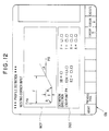
- Fig. 1 is a block diagram of an NC apparatus having an automatic programming function for realizing the present invention
- Fig. 2 is an external view of a CRT/MDI unit
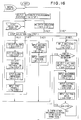
- Fig. 3 is a flowchart of a preferred example of processing for part profile input according to the present invention
- Figs. 4 through 16 are examples of conversational displays for part profile input according to the present invention.
- numeral 11 denotes an automatic programming unit
- 12 an NC control unit
- 13 a graphic display unit (CRT) 14
- keyboard a keyboard
- 16 changeover units The changeover units 15, 16 are illustrated as being switches for the sake of the description. In actuality, however, changeover is effected by software processing.
- the automatic programming unit 11 and NC control unit 12 are of microcomputer construction and incorporate an internal processor, a control program memory (ROM) and a RAM.
- the graphic display unit 13 and keyboard 14 are integrated into a single unit, as shown in Fig. 2, which is usually referred to as a CRT/MDI unit.
- the display screen is divided into a conversational display area 13a and a soft key area 13b.
- Keys 13c, 13c (see Fig. 2)... are provided to correspond to the soft key area. Pressing one of the keys enables the corresponding function displayed in the soft key area to be inputted.
- the keyboard 14 has an NC mode/automatic programming mode selection key 14a and a key group 14b, which includes keys serving as both arrow and numeric key, as well as the C key, R key and G key.
- Numeral 14c denotes an input key.
- processing up to the sixth step is executed conversationally in a manner similar to the flow of the conventional method shown in Fig. 16. If a soft key "NEXT PAGE" is pressed in the sixth step, a part profile input processing routine is started to display the part profile input screen and make possible a part profile input (see Fig. 4). Here it is determined whether it is necessary to enter a repeating shape or a standardized shape (step 101).
- the processor of the automatic programming unit 11 paints the graphic image PFG of each of the part profile elements on the display screen (CRT) along with the symbols PSF of the part profile elements.
- the operator selects "PATTERN INPUT" PIN from the soft key display 13b and presses the corresponding soft key 13c (see Fig. 2).
- the processor displays a menu for pattern profile selection shown in Fig. 5 on the soft key display 13b (step 103).
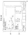
- the processor displays a groove series input screen on the display unit (CRT) (step 105; see Fig. 6).
- the groove series input screen includes a groove series pattern view CGP and a dimensions message DQS.
- EP signifies the end point of a pattern profile
- EDX the X coordinate thereof
- EZ the Z coordinate thereof
- N signifies the number of grooves
- PT signifies one groove pitch.
- DN signifies the direction of a groove, this direction being entered by an arrow key.
- WT represents groove width and DT groove depth.
- K1 - K4 signify groove corner machining. The C key is pressed for chamfering and the R key for rounding. No entry is made if corner machining is unnecessary.
- V1 - V4 signify the machining dimensions of the corners set by K1 - K4.
- the keyboard 14 is operated to key in numerical values and the like, as shown, for example, in Fig. 7, and the execute key NL is pressed (step 106).
- the processor of the automatic programming unit 11 paints the groove series profile EL4 on the screen at the end point P0 of the part profile PFG, as shown in Fig. 8. Further, the processor breaks the defined groove series profile into profile elements one at a time, calculates and stores the dimensions thereof and displays profile element symbols "G ⁇ G ⁇ G ⁇ ". In addition, the soft key display becomes the same as that shown in Fig. 4, entry of the groove series ends and entry of the next part profile becomes possible (steps 107 - 108).
- the processor displays a trapezoidal groove input screen on the display unit (CRT) (see Fig. 9).
- the trapezoidal groove input screen includes a trapezoidal groove pattern view TGP and a dimensions message DQS.
- WA signifies groove width
- MB bottom width signifies groove width
- a taper angle signifies groove depth
- K1 - K4 signify groove corner machining.
- the C key is pressed for chamfering and the R key for rounding. No entry is made if corner machining is unnecessary.
- the arrangement is such that dimensions indicated by the symbols in the pattern view TGP, as well as other data, can be set by responding to the message DQS.
- DN represents groove direction, which direction is entered by an arrow key.
- V1 - V4 signify the machining dimensions of the corners set by K1 - K4.
- the keyboard 14 is operated in response to the message DQS to key in numerical values and the like, as shown in Fig. 10, and the execute key NL is pressed.
- the processor of the automatic programming unit 11 paints the trapezoidal groove shape EL4 on the screen at the end point P0 of the part profile PFG, as shown in Fig. 11.
- the processor breaks the defined trapezoidal groove shape into profile elements one at a time, calculates and stores the dimensions thereof and displays profile element symbols "R ⁇ R ⁇ R ⁇ R".
- the soft key display becomes the same as that shown in Fig. 4, entry of the trapezoidal shape ends and entry of the next part profile becomes possible (step 201).
- the processor displays a nesting corner input screen on the display unit (CRT) (see Fig. 12).
- the nesting corner input screen includes a nesting corner pattern view NCP and a dimensions message DQS.
- NCP signifies nesting width, T nesting depth, R rounding and A taper angle.
- P* signifies definition of an end point.
- EDX is the X coordinate of the end point, and EZ is the Z coordinate thereof.
- the keyboard 14 is operated in response to the message DQS to key in numerical values and the like, as shown in Fig. 14, and the execute key NL is pressed.
- the processor of the automatic programming unit 11 paints the nesting corner shape EL4 on the screen at the end point P0 of the part profile PFG, as shown in Fig. 15.
- the processor breaks the defined nesting corner shape into profile elements one at a time, calculates and stores the dimensions thereof and displays profile element symbols " ⁇ R ⁇ R ⁇ ⁇ ".
- the soft key display becomes the same as that shown in Fig. 4, entry of the trapezoidal shape ends and entry of the next part profile becomes possible (step 301).
- a plurality of profile menus indicating repeating shapes or standardized shapes contained in a part profile are prepared, and data such as dimensions are applied to shapes selected from the profile menus to specify the repeating shape or standardized shape. Therefore, when entering a frequently used shape, the speed and operability of the part profile input operation can be improved by eliminating the laborious task of pressing arrow symbol keys and dimension input keys each time an input is made.
Landscapes
- Physics & Mathematics (AREA)
- Engineering & Computer Science (AREA)
- Geometry (AREA)
- Human Computer Interaction (AREA)
- Manufacturing & Machinery (AREA)
- General Physics & Mathematics (AREA)
- Automation & Control Theory (AREA)
- Numerical Control (AREA)
- Electrically Operated Instructional Devices (AREA)
Claims (7)
- Werkstückkontur-Eingabeverfahren in einer NC-Datenerzeugungsvorrichtung (11, 13, 14), bei dem eine Werkstückkontur durch eine Bedienungsperson eingegeben wird, wobei aufeinanderfolgende Konturelemente (EL) des Werkstücks unter Benutzung von Richtungspfeiltasten (14b) aufeinanderfolgend eingegeben werden und die Maße, welche die Konturelemente (EL) bestimmen, eingegeben werden und die NC-Datenerzeugungsvorrichtung (11, 13, 14) NC-Daten erzeugt, um einen Rohling in Übereinstimmung mit der durch die Bedienungsperson eingegebenenen Werkstückkontur zu bearbeiten,
dadurch gekennzeichnet, daß
eine Vielzahl von Konturmenüs vorgesehen sind, dieKonturmuster von sich wiederholenden Formen oder von standardisierten Formen kennzeichnen, welche in einer Werkstückkontur enthalten sein können,
die Bedienungsperson an einem Punkt (P₀) bei dem aufeinanderfolgenden Eingeben der Konturelemente (EL) unter Benutzung der Richtungspfeiltasten (14b) auf einen nächsten Teil der Werkstückkontur trifft, der eines der Konturmuster der sich wiederholenden Formen oder der standardisierten Formen ist,
die Bedienungsperson an dem Punkt (P₀) das eine Konturmuster unter Benutzung der Konturmenüs auswählt,
die NC-Datenerzeugungsvorrichtung (11, 13, 14) das ausgewählte Konturmuster auf einem Anzeigebildschirm (13) darstellt und eine Meldung anzeigt, die zur Angabe verschiedener Maße auffordert, und
die NC-Datenerzeugungsvorrichtung (11, 13, 14) eine sich wiederholende Form oder eine standardisierte Form auf der Grundlage von Daten, welche durch die Bedienungsperson eingegeben sind, in Reaktion auf die Meldung bestimmt und die bestimmte sich wiederholende Form oder standardisierte Form in die Werkstückkontur, welche durch die Bedienungsperson eingegeben ist, einführt. - Werkstückkontur-Eingabeverfahren nach Anspruch 1, bei dem die NC-Datenerzeugungsvorrichtung die eingegebene sich wiederholende Form oder die standardisierte Form in getrennte Konturelemente zerlegt, Maße derselben berechnet und die Maße speichert.
- Werkstückkontur-Eingabeverfahren nach Anspruch 1 oder 2, bei dem immer dann, wenn ein Konturelement (EL) eingegeben ist, das Konturelement (EL) in einer Form angezeigt wird, die einer bis dahin eingegebenen Werkstückkontur zugewiesen ist, und wenn eine sich wiederholende Form oder standardisierte Form eingegeben ist, dies Form in einer Form angezeigt wird, die einer bis dahin eingegebenen Werkstückkontur zugewiesen ist.
- Werkstückkontur-Eingabeverfahren nach einem der vorhergehenden Ansprüche, bei dem
die Vielzahl von Konturmenüs auf einem ersten Dialogbildschirm (Fig. 5), der für das Eingeben einer Werkstückkontur vorgesehen ist, für jedes Konturelement (EL) angezeigt werden,
wenn ein gewünschtes Konturmuster unter Benutzung der Konturmenüs ausgewählt ist, anstelle des ersten Dialogbildschirms (Fig. 5) ein zweiter Dialogbildschirm (Fig. 6, 9 oder 12), der eine Darstellung des Konturmusters und eine die Maße betreffende Meldung enthält, angezeigt wird und
wenn eine Form auf dem zweiten Dialogbildschirm (Fig. 6, 9 oder 12) durch Eingeben notwendiger Daten bestimmt ist, eine Rückkehr zu dem ersten Dialogbildschirm bewirkt wird und die bestimmte Form in einer Form (Fig. 8, 11 oder 15) dargestellt wird, welche der Werkstückkontur, die bis dahin eingegeben ist, zugewiesen ist. - Werkstückkontur-Eingabeverfahren nach einem der vorhergehenden Ansprüche, bei dem das bestimmte Konturmuster aus einer sich wiederholenden Form besteht, die eine Reihe von Nuten ist.
- Werkstückkontur-Eingabeverfahren nach einem der vorhergehenden Ansprüche, bei dem das bestimmte Konturmuster aus einer standardisierte Form besteht, die eine trapezförmige Nut ist.
- Werkstückkontur-Eingabeverfahren nach einem der vorhergehenden Ansprüche, bei dem das bestimmte Konturmuster aus einer standardisierten Form besteht, die eine zusammenhängende Eckenform ist.
Applications Claiming Priority (3)
| Application Number | Priority Date | Filing Date | Title |
|---|---|---|---|
| JP62319388A JPH01159705A (ja) | 1987-12-17 | 1987-12-17 | 部品形状入力方法 |
| JP3193/88 | 1987-12-17 | ||
| PCT/JP1988/001260 WO1989006004A1 (fr) | 1987-12-17 | 1988-12-13 | Procede d'introduction des donnees relatives au profil d'une piece |
Publications (3)
| Publication Number | Publication Date |
|---|---|
| EP0348522A1 EP0348522A1 (de) | 1990-01-03 |
| EP0348522A4 EP0348522A4 (en) | 1993-06-09 |
| EP0348522B1 true EP0348522B1 (de) | 1995-08-30 |
Family
ID=18109609
Family Applications (1)
| Application Number | Title | Priority Date | Filing Date |
|---|---|---|---|
| EP89900321A Expired - Lifetime EP0348522B1 (de) | 1987-12-17 | 1988-12-13 | Verfahren zur eingabe einer werkstückkontur |
Country Status (5)
| Country | Link |
|---|---|
| US (1) | US5089950A (de) |
| EP (1) | EP0348522B1 (de) |
| JP (1) | JPH01159705A (de) |
| DE (1) | DE3854390T2 (de) |
| WO (1) | WO1989006004A1 (de) |
Families Citing this family (21)
| Publication number | Priority date | Publication date | Assignee | Title |
|---|---|---|---|---|
| JPH02101506A (ja) * | 1988-10-08 | 1990-04-13 | Fanuc Ltd | 部品形状作成方法 |
| JPH084992B2 (ja) * | 1989-12-13 | 1996-01-24 | オ−クマ株式会社 | 数値制御情報作成機能における溝加工方法決定方法 |
| JP2993158B2 (ja) * | 1990-04-05 | 1999-12-20 | 三菱電機株式会社 | 数値制御装置 |
| JP2511166Y2 (ja) * | 1990-06-25 | 1996-09-18 | 豊田工機株式会社 | 形状デ―タ入力装置 |
| DE69220263T2 (de) * | 1991-03-15 | 1997-11-27 | Spatial Technology Inc | Methode und Apparat für maschinelle Werkstückbearbeitung mittels eines solidmodel-Algorithmus |
| JPH05197411A (ja) * | 1992-01-20 | 1993-08-06 | Fanuc Ltd | 加工プログラム作成方法 |
| DE4240890C2 (de) * | 1992-02-17 | 1996-09-26 | Mitsubishi Electric Corp | CAD-Vorrichtung zum Erzeugen eines NC-Programms |
| US6219055B1 (en) * | 1995-12-20 | 2001-04-17 | Solidworks Corporation | Computer based forming tool |
| DE19614130C2 (de) * | 1996-04-10 | 2002-11-21 | Agie Sa | Verfahren und Vorrichtung zur Steuerung einer Werkzeugmaschine, insbesondere einer Funkenerosionsmaschine |
| GB2350207B (en) * | 1999-05-11 | 2003-08-20 | Falcon Machine Tools Co Ltd | Interactive system between machine tool and operator |
| GB2350442A (en) * | 1999-05-18 | 2000-11-29 | Falcon Machine Tools Co Ltd | Computerised numerical controller with profile path editor |
| US7792604B2 (en) * | 2005-03-23 | 2010-09-07 | Hurco Companies, Inc. | Method of performing additive lookahead for adaptive cutting feedrate control |
| US7933677B2 (en) * | 2006-08-04 | 2011-04-26 | Hurco Companies, Inc. | System and method for surface finish management |
| US8725283B2 (en) * | 2006-08-04 | 2014-05-13 | Hurco Companies, Inc. | Generalized kinematics system |
| US8024068B2 (en) | 2006-08-04 | 2011-09-20 | Hurco Companies, Inc. | Machine tool control system |
| TWI353496B (en) * | 2006-08-04 | 2011-12-01 | Hurco Co Inc | System and method and computer readable medium for |
| USD582926S1 (en) * | 2007-09-17 | 2008-12-16 | Sap Ag | Display panel with a transitional computer-generated icon |
| USD582925S1 (en) * | 2007-09-17 | 2008-12-16 | Sap Ag | Display panel with a computer-generated icon |
| USD582931S1 (en) * | 2007-09-17 | 2008-12-16 | Sap Ag | Display panel with a computer-generated icon |
| USD582923S1 (en) * | 2007-09-17 | 2008-12-16 | Sap Ag | Display panel with a computer-generated icon |
| USD592218S1 (en) * | 2007-09-17 | 2009-05-12 | Sap Ag | Display panel with a computer-generated icon |
Citations (2)
| Publication number | Priority date | Publication date | Assignee | Title |
|---|---|---|---|---|
| EP0044192A1 (de) * | 1980-07-10 | 1982-01-20 | Fanuc Ltd. | Verfahren zum Vorbereiten numerischer Steuerungsinformationen |
| EP0078856A1 (de) * | 1981-05-18 | 1983-05-18 | Fanuc Ltd. | Numerische steueranordnung |
Family Cites Families (6)
| Publication number | Priority date | Publication date | Assignee | Title |
|---|---|---|---|---|
| JPS57121443A (en) * | 1981-01-20 | 1982-07-28 | Okuma Mach Works Ltd | Data input method for numerical control system |
| JPS58163001A (ja) * | 1982-03-23 | 1983-09-27 | Toyoda Mach Works Ltd | 干渉チエツク機能を備えた数値制御装置 |
| DE3608438A1 (de) * | 1985-03-13 | 1986-09-18 | Toshiba Kikai K.K., Tokio/Tokyo | Verfahren zum berechnen von freien gekruemmten flaechen mittels computergestuetztem design cad und computergestuetzter herstellung cam und numerischer steuerung nc |
| JPS61255408A (ja) * | 1985-05-07 | 1986-11-13 | Hitachi Seiki Co Ltd | ワ−ク形状のリスト入力装置 |
| JPS63250707A (ja) * | 1987-04-07 | 1988-10-18 | Fanuc Ltd | 部品形状入力方法 |
| US4928221A (en) * | 1988-04-11 | 1990-05-22 | Westinghouse Electric Corp. | Part program generating system |
-
1987
- 1987-12-17 JP JP62319388A patent/JPH01159705A/ja active Pending
-
1988
- 1988-12-13 WO PCT/JP1988/001260 patent/WO1989006004A1/ja not_active Ceased
- 1988-12-13 US US07/397,455 patent/US5089950A/en not_active Expired - Fee Related
- 1988-12-13 DE DE3854390T patent/DE3854390T2/de not_active Expired - Fee Related
- 1988-12-13 EP EP89900321A patent/EP0348522B1/de not_active Expired - Lifetime
Patent Citations (3)
| Publication number | Priority date | Publication date | Assignee | Title |
|---|---|---|---|---|
| EP0044192A1 (de) * | 1980-07-10 | 1982-01-20 | Fanuc Ltd. | Verfahren zum Vorbereiten numerischer Steuerungsinformationen |
| JPS5719809A (en) * | 1980-07-10 | 1982-02-02 | Fanuc Ltd | Numerical control information generating system |
| EP0078856A1 (de) * | 1981-05-18 | 1983-05-18 | Fanuc Ltd. | Numerische steueranordnung |
Non-Patent Citations (1)
| Title |
|---|
| PATENT ABSTRACTS OF JAPAN vol. 10, no. 22 (P-424)(2079) 28 January 1986 & JP-A-60 176 107 * |
Also Published As
| Publication number | Publication date |
|---|---|
| DE3854390T2 (de) | 1996-02-08 |
| DE3854390D1 (de) | 1995-10-05 |
| US5089950A (en) | 1992-02-18 |
| JPH01159705A (ja) | 1989-06-22 |
| WO1989006004A1 (fr) | 1989-06-29 |
| EP0348522A4 (en) | 1993-06-09 |
| EP0348522A1 (de) | 1990-01-03 |
Similar Documents
| Publication | Publication Date | Title |
|---|---|---|
| EP0348522B1 (de) | Verfahren zur eingabe einer werkstückkontur | |
| EP0303705B1 (de) | Verfahren zur eingabe der profildaten | |
| US4490781A (en) | System and method for preparing numerical control information | |
| EP0078856B2 (de) | Numerische steueranordnung | |
| US5177689A (en) | Cad/cam apparatus for enhancing operator entry of machining attributes and geometric shapes | |
| US4788636A (en) | Interactive device for entering graphic data | |
| EP0034506A2 (de) | Bildanzeigesystem | |
| US4901220A (en) | Part profile input method | |
| EP0247204B1 (de) | Interaktive programmierungsanordnung | |
| US4891763A (en) | NC program editing and programming device | |
| EP0348533B1 (de) | Selbsttätiges programmierungsverfahren | |
| US5099432A (en) | Method for determining machining process in numerical control information generating function | |
| EP0079388B1 (de) | Numerisches steuerverfahren | |
| EP0144428B1 (de) | Verfahren zur unterschiedlichen behandlung von winkeldaten | |
| US5029068A (en) | NC data creation method | |
| US5072398A (en) | Figure definition method in automatic programming | |
| US5146402A (en) | Profile definition method | |
| JPH06202721A (ja) | 数値制御情報作成装置 | |
| EP0165999A1 (de) | Verfahren zur auswahl eines werkzeugs für selbsttätige programmierung | |
| US5063517A (en) | Profile revising method | |
| EP0148947A1 (de) | Verfahren zur dateneingabe | |
| EP0332703A1 (de) | Dateneingabesystem | |
| EP0519077A1 (de) | Interaktiv-artig numerisch gesteuertes gerät | |
| EP0530364A1 (de) | Interaktive numerische steuerung | |
| EP0453570A1 (de) | Verfahren zum vorbereiten eines nc-programms für ein interaktives numerisches steuer- oder automatisches programmiergerät |
Legal Events
| Date | Code | Title | Description |
|---|---|---|---|
| PUAI | Public reference made under article 153(3) epc to a published international application that has entered the european phase |
Free format text: ORIGINAL CODE: 0009012 |
|
| 17P | Request for examination filed |
Effective date: 19890831 |
|
| AK | Designated contracting states |
Kind code of ref document: A1 Designated state(s): DE FR GB |
|
| A4 | Supplementary search report drawn up and despatched |
Effective date: 19930420 |
|
| AK | Designated contracting states |
Kind code of ref document: A4 Designated state(s): DE FR GB |
|
| 17Q | First examination report despatched |
Effective date: 19940610 |
|
| GRAA | (expected) grant |
Free format text: ORIGINAL CODE: 0009210 |
|
| AK | Designated contracting states |
Kind code of ref document: B1 Designated state(s): DE FR GB |
|
| PG25 | Lapsed in a contracting state [announced via postgrant information from national office to epo] |
Ref country code: FR Free format text: THE PATENT HAS BEEN ANNULLED BY A DECISION OF A NATIONAL AUTHORITY Effective date: 19950830 |
|
| REF | Corresponds to: |
Ref document number: 3854390 Country of ref document: DE Date of ref document: 19951005 |
|
| PG25 | Lapsed in a contracting state [announced via postgrant information from national office to epo] |
Ref country code: GB Effective date: 19951213 |
|
| PGFP | Annual fee paid to national office [announced via postgrant information from national office to epo] |
Ref country code: DE Payment date: 19951214 Year of fee payment: 8 |
|
| EN | Fr: translation not filed | ||
| PLBE | No opposition filed within time limit |
Free format text: ORIGINAL CODE: 0009261 |
|
| STAA | Information on the status of an ep patent application or granted ep patent |
Free format text: STATUS: NO OPPOSITION FILED WITHIN TIME LIMIT |
|
| GBPC | Gb: european patent ceased through non-payment of renewal fee |
Effective date: 19951213 |
|
| 26N | No opposition filed | ||
| PG25 | Lapsed in a contracting state [announced via postgrant information from national office to epo] |
Ref country code: DE Effective date: 19970902 |