EP0348522A1 - Verfahren zur eingabe einer werkstückkontur - Google Patents
Verfahren zur eingabe einer werkstückkontur Download PDFInfo
- Publication number
- EP0348522A1 EP0348522A1 EP89900321A EP89900321A EP0348522A1 EP 0348522 A1 EP0348522 A1 EP 0348522A1 EP 89900321 A EP89900321 A EP 89900321A EP 89900321 A EP89900321 A EP 89900321A EP 0348522 A1 EP0348522 A1 EP 0348522A1
- Authority
- EP
- European Patent Office
- Prior art keywords
- profile
- shape
- part profile
- dimensions
- inputted
- Prior art date
- Legal status (The legal status is an assumption and is not a legal conclusion. Google has not performed a legal analysis and makes no representation as to the accuracy of the status listed.)
- Granted
Links
- 238000000034 method Methods 0.000 title claims description 12
- 230000004044 response Effects 0.000 claims description 15
- 230000002452 interceptive effect Effects 0.000 abstract 1
- 238000003754 machining Methods 0.000 description 10
- 230000006870 function Effects 0.000 description 8
- 238000003825 pressing Methods 0.000 description 5
- 239000003973 paint Substances 0.000 description 4
- 238000007796 conventional method Methods 0.000 description 2
- 238000010586 diagram Methods 0.000 description 2
- 238000010276 construction Methods 0.000 description 1
- 239000000463 material Substances 0.000 description 1
- 230000003746 surface roughness Effects 0.000 description 1
Images


Classifications
-
- G—PHYSICS
- G05—CONTROLLING; REGULATING
- G05B—CONTROL OR REGULATING SYSTEMS IN GENERAL; FUNCTIONAL ELEMENTS OF SUCH SYSTEMS; MONITORING OR TESTING ARRANGEMENTS FOR SUCH SYSTEMS OR ELEMENTS
- G05B19/00—Programme-control systems
- G05B19/02—Programme-control systems electric
- G05B19/18—Numerical control [NC], i.e. automatically operating machines, in particular machine tools, e.g. in a manufacturing environment, so as to execute positioning, movement or co-ordinated operations by means of programme data in numerical form
- G05B19/4093—Numerical control [NC], i.e. automatically operating machines, in particular machine tools, e.g. in a manufacturing environment, so as to execute positioning, movement or co-ordinated operations by means of programme data in numerical form characterised by part programming, e.g. entry of geometrical information as taken from a technical drawing, combining this with machining and material information to obtain control information, named part programme, for the NC machine
- G05B19/40931—Numerical control [NC], i.e. automatically operating machines, in particular machine tools, e.g. in a manufacturing environment, so as to execute positioning, movement or co-ordinated operations by means of programme data in numerical form characterised by part programming, e.g. entry of geometrical information as taken from a technical drawing, combining this with machining and material information to obtain control information, named part programme, for the NC machine concerning programming of geometry
- G05B19/40932—Shape input
-
- G—PHYSICS
- G05—CONTROLLING; REGULATING
- G05B—CONTROL OR REGULATING SYSTEMS IN GENERAL; FUNCTIONAL ELEMENTS OF SUCH SYSTEMS; MONITORING OR TESTING ARRANGEMENTS FOR SUCH SYSTEMS OR ELEMENTS
- G05B2219/00—Program-control systems
- G05B2219/30—Nc systems
- G05B2219/33—Director till display
- G05B2219/33185—Rs232c switch box, break out box, to connect different devices
-
- G—PHYSICS
- G05—CONTROLLING; REGULATING
- G05B—CONTROL OR REGULATING SYSTEMS IN GENERAL; FUNCTIONAL ELEMENTS OF SUCH SYSTEMS; MONITORING OR TESTING ARRANGEMENTS FOR SUCH SYSTEMS OR ELEMENTS
- G05B2219/00—Program-control systems
- G05B2219/30—Nc systems
- G05B2219/36—Nc in input of data, input key till input tape
- G05B2219/36129—Menu keys, function of keys soft defined
-
- G—PHYSICS
- G05—CONTROLLING; REGULATING
- G05B—CONTROL OR REGULATING SYSTEMS IN GENERAL; FUNCTIONAL ELEMENTS OF SUCH SYSTEMS; MONITORING OR TESTING ARRANGEMENTS FOR SUCH SYSTEMS OR ELEMENTS
- G05B2219/00—Program-control systems
- G05B2219/30—Nc systems
- G05B2219/36—Nc in input of data, input key till input tape
- G05B2219/36161—Common program panel for nc, pic, switch display diagnostic or part
-
- G—PHYSICS
- G05—CONTROLLING; REGULATING
- G05B—CONTROL OR REGULATING SYSTEMS IN GENERAL; FUNCTIONAL ELEMENTS OF SUCH SYSTEMS; MONITORING OR TESTING ARRANGEMENTS FOR SUCH SYSTEMS OR ELEMENTS
- G05B2219/00—Program-control systems
- G05B2219/30—Nc systems
- G05B2219/50—Machine tool, machine tool null till machine tool work handling
- G05B2219/50213—Grooving of different forms or parallel to each other, grooving cycle
-
- Y—GENERAL TAGGING OF NEW TECHNOLOGICAL DEVELOPMENTS; GENERAL TAGGING OF CROSS-SECTIONAL TECHNOLOGIES SPANNING OVER SEVERAL SECTIONS OF THE IPC; TECHNICAL SUBJECTS COVERED BY FORMER USPC CROSS-REFERENCE ART COLLECTIONS [XRACs] AND DIGESTS
- Y02—TECHNOLOGIES OR APPLICATIONS FOR MITIGATION OR ADAPTATION AGAINST CLIMATE CHANGE
- Y02P—CLIMATE CHANGE MITIGATION TECHNOLOGIES IN THE PRODUCTION OR PROCESSING OF GOODS
- Y02P90/00—Enabling technologies with a potential contribution to greenhouse gas [GHG] emissions mitigation
- Y02P90/02—Total factory control, e.g. smart factories, flexible manufacturing systems [FMS] or integrated manufacturing systems [IMS]
Definitions
- This invention relates to a part profile input method for entering a part profile using arrow keys and, more particularly, to a part profile input method for specifying a part profile which includes a repeating shape and standard shape.
- An automatic programming system is available in which a conversational display and a function key (soft key) display are each presented in accordance with each step of a plurality of data input steps, a specific function key (soft key) on the function key display is pressed to thereby execute processing conforming to the function, and an NC program is prepared using data inputted while referring to the conversational display.
- a conversational display and a function key (soft key) display are each presented in accordance with each step of a plurality of data input steps, a specific function key (soft key) on the function key display is pressed to thereby execute processing conforming to the function, and an NC program is prepared using data inputted while referring to the conversational display.
- predetermined message screens are successively displayed on a display screen.
- An operator responds to these messages by entering the necessary data from a keyboard.
- NC program NC data for a lathe is created using all of the entered data.
- arrow keys T, ⁇ , ⁇ , ⁇ , ⁇ , ⁇ , ⁇ , ⁇ , ⁇ , ⁇ , ?,
- a thread-cutting key C key
- a rounding key R key
- a grooving key G key
- a corner-removal key which are provided on a keyboard
- a prompt calling for the dimensions of this element is displayed.
- dimensions taken from the design drawing are inputted, whereupon profile element symbols PFS and graphic images PFG of these profile elements appear on the display screen.
- prompts appear calling for the X coordinate (X) of the end point of the straight line, the Z coordinate (Z) of this end point, whether or not this straight line contacts the preceding profile element or the next profile element, the angle (A) which the straight line forms with the Z axis, etc.
- the dimensions written on the drawing are entered in response to these prompts. However, when the prescribed dimensions are not written on the drawing (as in the case of the angle formed with the Z axis, for example), this input is not required.
- a repeating shape such as a series of grooves or a standardized shape, e.g., a shape for which the machining profile is standardized as in the case of, for example, a trapezoidal groove or nesting shape.
- Fig. 18 is a view for entering a profile having a series of grooves.
- an arrow key, grooving key ( G key) and, if necessary, the chamfering key (C key) and rounding key (R key) provided on the keyboard must be operated for every groove, the dimensions of the elements must be entered whenever an arrow key is pressed, and the same operations must be performed repeatedly a number of times equivalent to the number of grooves.
- the shape when entering a standardized shape such as a trapezoidal groove or nesting shape, the shape must be specified on each occasion using arrow keys a number of times even though the shape is standardized and frequently appears.
- an object of the present invention is to provide a part profile input method in which, when entering a frequently used shape, such as a repeating shape or standardized shape, the speed and operability of the part profile input operation can be improved by eliminating the laborious task of pressing arrow symbol keys and dimension input keys each time an input is made.
- a plurality of profile menus for designating the profile patterns of repeating shapes and standardized shapes contained in a part profile are provided, a desired profile pattern is selected using the profile menus, the selected pattern profile is displayed on a display screen, a message regarding various dimensions is displayed, and a repeating shape or standardized shape is specified based on data entered in response to the message.
- Fig. 1 is a block diagram of an NC apparatus having an automatic programming function for realizing the present invention
- Fig. 2 is an external view of a CRT/MDI unit
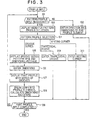
- Fig. 3 is a flowchart of processing for part profile input according to the present invention
- Figs. 4 through 16 are examples of conversational displays for part profile input according to the present invention.
- numeral 11 denotes an automatic programming unit
- 12 an NC control unit
- 13 a graphic display unit (CRT) 14
- keyboard a keyboard
- 16 changeover units The changeover units 15, 16 are illustrated as being switches for the sake of the description. In actuality, however, changeover is effected by software processing.
- the automatic programming unit 11 and NC control unit 12 are of microcomputer construction and incorporate an internal processor, a control program memory (ROM) and a RAM.
- the graphic display unit 13 and keyboard 14 are integrated into a single unit, as shown in Fig. 2, which is usually referred to as a CRT/MDI unit.
- the display screen is divided into a conversational display area 13a and a soft key area 13b.
- Keys 13c, 13c (see Fig. 2)... are provided to correspond to the soft key area. Pressing one of the keys enables the corresponding function displayed in the soft key area to be inputted.
- the keyboard 14 has an N C mode/automatic programming mode selection key 14a and a key group 14b, which includes keys serving as both arrow and numeric key, as well as the C key, R key and G key.
- Numeral 14c denotes an input key.
- processing up to the sixth step is executed conversationally in a manner similar to the flow of the conventional method shown in Fig. 16. If a soft key "NEXT PAGE" is pressed in the sixth step, a part profile input processing routine is started to display the part profile input screen and make possible a part profile input (see Fig. 4). Here it is determined whether it is necessary to enter a repeating shape or a standardized shape (step 101).
- the processor of the automatic programming unit 11 paints the graphic image PFG of each of the part profile elements on the display screen (CRT) along with the symbols PSF of the part profile elements.
- the operator selects "PATTERN INPUT" PIN from the soft key display 13b and presses the corresponding soft key 13c (see Fig. 2).
- the processor displays a menu for pattern profile selection shown in Fig. 5 on the soft key display 13b (step 103).
- the processor displays a groove series input screen on the display unit (CRT) (step 105; see Fig. 6).
- the groove series input screen includes a groove series pattern view CGP and a dimensions message DQS.
- EP signifies the end point of a pattern profile
- EDX the X coordinate thereof
- EZ the Z coordinate thereof
- N signifies the number of grooves
- PT signifies one groove pitch.
- DN signifies the direction of a groove, this direction being entered by an arrow key.
- WT represents groove width and DT groove depth.
- K 1 - K 4 signify groove corner machining. The C key is pressed for chamfering and the R key for rounding. No entry is made if corner machining is unnecessary.
- V 1 - V 4 signify the machining dimensions of the corners set by K 1 - K 4 .
- the keyboard 14 is operated to key in numerical values and the like, as shown, for example, in Fig. 7, and the execute key N L is pressed (step 106).
- the processor of the automatic programming unit 11 paints the groove series profile EL 4 on the screen at the end point P o of the part profile PFG, as shown in Fig. 8. Further, the processor breaks the defined groove series profile into profile elements one at a time, calculates and stores the dimensions thereof and displays profile element symbols "G ⁇ G ⁇ G ⁇ ". In addition, the soft key display becomes the same as that shown in Fig. 4, entry of the groove series ends and entry of the next part profile becomes possible (steps 107 - 108).
- the processor displays a trapezoidal groove input screen on the display unit (CRT) (see Fig. 9).
- the trapezoidal groove input screen includes a trapezoidal groove pattern view TGP and a dimensions message DQS.
- WA signifies groove width
- M B bottom width A taper angle
- DT groove depth a dimension message
- K1 - K 4 signify groove corner machining. The C key is pressed for chamfering and the R key for rounding. No entry is made if corner machining is unnecessary.
- the arrangement is such that dimensions indicated by the symbols in the pattern view TGP, as well as other data, can be set by responding to the message DQS.
- DN represents groove direction, which direction is entered by an arrow key.
- V 1 - V 4 signify the machining dimensions of the corners set by K1 - K 4'
- the keyboard 14 is operated in response to the message DQS to key in numerical values and the like, as shown in Fig. 10, and the execute key NL is pressed.
- the processor of the automatic programming unit 11 paints the trapezoidal groove shape EL 4 on the screen at the end point P 0 of the part profile PFG, as shown in Fig. 11.
- the processor breaks the defined trapezoidal groove shape into profile elements one at a time, calculates and stores the dimensions thereof and displays profile element symbols "R ⁇ R ⁇ R ⁇ R".
- the soft key display becomes the same as that shown in Fig. 4, entry of the trapezoidal shape ends and entry of the next part profile becomes possible (step 201).
- the processor displays a nesting corner input screen on the display unit (CRT) (see Fig. 12).
- the nesting corner input screen includes a nesting corner pattern view NCP and a dimensions message DQS.
- NCP signifies nesting width, T nesting depth, R rounding and A taper angle.
- P * signifies definition of an end point.
- EDX is the X coordinate of the end point, and EZ is the Z coordinate thereof.
- the keyboard 14 is operated in response to the message DQS to key in numerical values and the like, as shown in Fig. 14, and the execute key NL is pressed.
- the processor of the automatic programming unit 11 paints the nesting corner shape EL 4 on the screen at the end point P 0 of the part profile PFG, as shown in Fig. 15.
- the processor breaks the defined.nesting corner shape into profile elements one at a time, calculates and stores the dimensions thereof and displays profile element symbols " ⁇ R ⁇ R ⁇ ⁇ ".
- the soft key display becomes the same as that shown in Fig. 4, entry of the trapezoidal shape ends and entry of the next part profile becomes possible (step 301).
- a plurality of profile menus indicating repeating shapes or standardized shapes contained in a part profile are prepared, and data such as dimensions are applied to shapes selected from the profile menus to specify the repeating shape or standardized shape. Therefore, when entering a frequently used shape, the speed and operability of the part profile input operation can be improved by eliminating the laborious task of pressing arrow symbol keys and dimension input keys each time an input is made.
Landscapes
- Physics & Mathematics (AREA)
- Engineering & Computer Science (AREA)
- Geometry (AREA)
- Human Computer Interaction (AREA)
- Manufacturing & Machinery (AREA)
- General Physics & Mathematics (AREA)
- Automation & Control Theory (AREA)
- Numerical Control (AREA)
- Electrically Operated Instructional Devices (AREA)
Applications Claiming Priority (3)
| Application Number | Priority Date | Filing Date | Title |
|---|---|---|---|
| JP62319388A JPH01159705A (ja) | 1987-12-17 | 1987-12-17 | 部品形状入力方法 |
| JP3193/88 | 1987-12-17 | ||
| PCT/JP1988/001260 WO1989006004A1 (fr) | 1987-12-17 | 1988-12-13 | Procede d'introduction des donnees relatives au profil d'une piece |
Publications (3)
| Publication Number | Publication Date |
|---|---|
| EP0348522A1 true EP0348522A1 (de) | 1990-01-03 |
| EP0348522A4 EP0348522A4 (en) | 1993-06-09 |
| EP0348522B1 EP0348522B1 (de) | 1995-08-30 |
Family
ID=18109609
Family Applications (1)
| Application Number | Title | Priority Date | Filing Date |
|---|---|---|---|
| EP89900321A Expired - Lifetime EP0348522B1 (de) | 1987-12-17 | 1988-12-13 | Verfahren zur eingabe einer werkstückkontur |
Country Status (5)
| Country | Link |
|---|---|
| US (1) | US5089950A (de) |
| EP (1) | EP0348522B1 (de) |
| JP (1) | JPH01159705A (de) |
| DE (1) | DE3854390T2 (de) |
| WO (1) | WO1989006004A1 (de) |
Cited By (4)
| Publication number | Priority date | Publication date | Assignee | Title |
|---|---|---|---|---|
| DE4240890A1 (en) * | 1992-02-17 | 1993-08-26 | Mitsubishi Electric Corp | Graphics and machining program processor for NL machine programming - has component size information used to generate list and diagrams for NL programming |
| EP0576681A4 (de) * | 1992-01-20 | 1994-08-03 | Fanuc Ltd. | |
| GB2350207A (en) * | 1999-05-11 | 2000-11-22 | Falcon Machine Tools Co Ltd | Interactive system between machine tool and operator |
| FR2796170A1 (fr) * | 1999-05-18 | 2001-01-12 | Falcon Machine Tools Co Ltd | Dispositif de commande numerique par calculateur pour machine-outil |
Families Citing this family (17)
| Publication number | Priority date | Publication date | Assignee | Title |
|---|---|---|---|---|
| JPH02101506A (ja) * | 1988-10-08 | 1990-04-13 | Fanuc Ltd | 部品形状作成方法 |
| JPH084992B2 (ja) * | 1989-12-13 | 1996-01-24 | オ−クマ株式会社 | 数値制御情報作成機能における溝加工方法決定方法 |
| JP2993158B2 (ja) * | 1990-04-05 | 1999-12-20 | 三菱電機株式会社 | 数値制御装置 |
| JP2511166Y2 (ja) * | 1990-06-25 | 1996-09-18 | 豊田工機株式会社 | 形状デ―タ入力装置 |
| DE69220263T2 (de) * | 1991-03-15 | 1997-11-27 | Spatial Technology Inc | Methode und Apparat für maschinelle Werkstückbearbeitung mittels eines solidmodel-Algorithmus |
| US6219055B1 (en) * | 1995-12-20 | 2001-04-17 | Solidworks Corporation | Computer based forming tool |
| DE19614130C2 (de) * | 1996-04-10 | 2002-11-21 | Agie Sa | Verfahren und Vorrichtung zur Steuerung einer Werkzeugmaschine, insbesondere einer Funkenerosionsmaschine |
| SG173407A1 (en) * | 2005-03-23 | 2011-08-29 | Hurco Co Inc | Method of tolerance-based trajectory planning and control |
| US8725283B2 (en) * | 2006-08-04 | 2014-05-13 | Hurco Companies, Inc. | Generalized kinematics system |
| TWI353496B (en) * | 2006-08-04 | 2011-12-01 | Hurco Co Inc | System and method and computer readable medium for |
| US8024068B2 (en) | 2006-08-04 | 2011-09-20 | Hurco Companies, Inc. | Machine tool control system |
| US7933677B2 (en) * | 2006-08-04 | 2011-04-26 | Hurco Companies, Inc. | System and method for surface finish management |
| USD582925S1 (en) * | 2007-09-17 | 2008-12-16 | Sap Ag | Display panel with a computer-generated icon |
| USD582923S1 (en) * | 2007-09-17 | 2008-12-16 | Sap Ag | Display panel with a computer-generated icon |
| USD582926S1 (en) * | 2007-09-17 | 2008-12-16 | Sap Ag | Display panel with a transitional computer-generated icon |
| USD592218S1 (en) * | 2007-09-17 | 2009-05-12 | Sap Ag | Display panel with a computer-generated icon |
| USD582931S1 (en) * | 2007-09-17 | 2008-12-16 | Sap Ag | Display panel with a computer-generated icon |
Family Cites Families (8)
| Publication number | Priority date | Publication date | Assignee | Title |
|---|---|---|---|---|
| JPS5719809A (en) * | 1980-07-10 | 1982-02-02 | Fanuc Ltd | Numerical control information generating system |
| JPS57121443A (en) * | 1981-01-20 | 1982-07-28 | Okuma Mach Works Ltd | Data input method for numerical control system |
| JPS57189207A (en) * | 1981-05-18 | 1982-11-20 | Fanuc Ltd | Numerical control system |
| JPS58163001A (ja) * | 1982-03-23 | 1983-09-27 | Toyoda Mach Works Ltd | 干渉チエツク機能を備えた数値制御装置 |
| KR900003123B1 (ko) * | 1985-03-13 | 1990-05-08 | 도시바 기까이 가부시기 가이샤 | 자유표면 평가방법 및 그의 nc 시스템 |
| JPS61255408A (ja) * | 1985-05-07 | 1986-11-13 | Hitachi Seiki Co Ltd | ワ−ク形状のリスト入力装置 |
| JPS63250707A (ja) * | 1987-04-07 | 1988-10-18 | Fanuc Ltd | 部品形状入力方法 |
| US4928221A (en) * | 1988-04-11 | 1990-05-22 | Westinghouse Electric Corp. | Part program generating system |
-
1987
- 1987-12-17 JP JP62319388A patent/JPH01159705A/ja active Pending
-
1988
- 1988-12-13 US US07/397,455 patent/US5089950A/en not_active Expired - Fee Related
- 1988-12-13 WO PCT/JP1988/001260 patent/WO1989006004A1/ja not_active Ceased
- 1988-12-13 DE DE3854390T patent/DE3854390T2/de not_active Expired - Fee Related
- 1988-12-13 EP EP89900321A patent/EP0348522B1/de not_active Expired - Lifetime
Cited By (7)
| Publication number | Priority date | Publication date | Assignee | Title |
|---|---|---|---|---|
| EP0576681A4 (de) * | 1992-01-20 | 1994-08-03 | Fanuc Ltd. | |
| DE4240890A1 (en) * | 1992-02-17 | 1993-08-26 | Mitsubishi Electric Corp | Graphics and machining program processor for NL machine programming - has component size information used to generate list and diagrams for NL programming |
| US5581676A (en) * | 1992-02-17 | 1996-12-03 | Mitsubishi Denki Kabushiki Kaisha | Drawing processor and machining program processor for generating a machining program and method therefor |
| GB2350207A (en) * | 1999-05-11 | 2000-11-22 | Falcon Machine Tools Co Ltd | Interactive system between machine tool and operator |
| ES2154223A1 (es) * | 1999-05-11 | 2001-03-16 | Falcon Machine Tools Co Ltd | Sistema interactivo entre una maquina-herramienta y un operario. |
| GB2350207B (en) * | 1999-05-11 | 2003-08-20 | Falcon Machine Tools Co Ltd | Interactive system between machine tool and operator |
| FR2796170A1 (fr) * | 1999-05-18 | 2001-01-12 | Falcon Machine Tools Co Ltd | Dispositif de commande numerique par calculateur pour machine-outil |
Also Published As
| Publication number | Publication date |
|---|---|
| DE3854390D1 (de) | 1995-10-05 |
| EP0348522A4 (en) | 1993-06-09 |
| WO1989006004A1 (fr) | 1989-06-29 |
| EP0348522B1 (de) | 1995-08-30 |
| US5089950A (en) | 1992-02-18 |
| JPH01159705A (ja) | 1989-06-22 |
| DE3854390T2 (de) | 1996-02-08 |
Similar Documents
| Publication | Publication Date | Title |
|---|---|---|
| EP0348522B1 (de) | Verfahren zur eingabe einer werkstückkontur | |
| US4926311A (en) | Part profile input method | |
| US4490781A (en) | System and method for preparing numerical control information | |
| US4788636A (en) | Interactive device for entering graphic data | |
| EP0076328B1 (de) | Programmieranordnung | |
| US5177689A (en) | Cad/cam apparatus for enhancing operator entry of machining attributes and geometric shapes | |
| EP0078856B2 (de) | Numerische steueranordnung | |
| EP0247204B1 (de) | Interaktive programmierungsanordnung | |
| US4901220A (en) | Part profile input method | |
| US4891763A (en) | NC program editing and programming device | |
| EP0127122B1 (de) | Numerisches Steuersystem mit einer Anzeige-Einheit und vom System gesteuerte Werkzeugmaschine | |
| EP0348533B1 (de) | Selbsttätiges programmierungsverfahren | |
| US5006977A (en) | Figure element revising method | |
| EP0144428A1 (de) | Verfahren zur unterschiedlichen behandlung von winkeldaten | |
| US5072398A (en) | Figure definition method in automatic programming | |
| US5146402A (en) | Profile definition method | |
| US5029068A (en) | NC data creation method | |
| JPH06202721A (ja) | 数値制御情報作成装置 | |
| US5063517A (en) | Profile revising method | |
| EP0165999A1 (de) | Verfahren zur auswahl eines werkzeugs für selbsttätige programmierung | |
| EP0332703A1 (de) | Dateneingabesystem | |
| EP0519077A1 (de) | Interaktiv-artig numerisch gesteuertes gerät | |
| EP0453570A1 (de) | Verfahren zum vorbereiten eines nc-programms für ein interaktives numerisches steuer- oder automatisches programmiergerät | |
| EP0383940A1 (de) | Eingabeverfahren von relativen daten in form einer kurve. | |
| KR910009239B1 (ko) | 수치제어 장치의 가공데이타 작성방법 |
Legal Events
| Date | Code | Title | Description |
|---|---|---|---|
| PUAI | Public reference made under article 153(3) epc to a published international application that has entered the european phase |
Free format text: ORIGINAL CODE: 0009012 |
|
| 17P | Request for examination filed |
Effective date: 19890831 |
|
| AK | Designated contracting states |
Kind code of ref document: A1 Designated state(s): DE FR GB |
|
| A4 | Supplementary search report drawn up and despatched |
Effective date: 19930420 |
|
| AK | Designated contracting states |
Kind code of ref document: A4 Designated state(s): DE FR GB |
|
| 17Q | First examination report despatched |
Effective date: 19940610 |
|
| GRAA | (expected) grant |
Free format text: ORIGINAL CODE: 0009210 |
|
| AK | Designated contracting states |
Kind code of ref document: B1 Designated state(s): DE FR GB |
|
| PG25 | Lapsed in a contracting state [announced via postgrant information from national office to epo] |
Ref country code: FR Free format text: THE PATENT HAS BEEN ANNULLED BY A DECISION OF A NATIONAL AUTHORITY Effective date: 19950830 |
|
| REF | Corresponds to: |
Ref document number: 3854390 Country of ref document: DE Date of ref document: 19951005 |
|
| PG25 | Lapsed in a contracting state [announced via postgrant information from national office to epo] |
Ref country code: GB Effective date: 19951213 |
|
| PGFP | Annual fee paid to national office [announced via postgrant information from national office to epo] |
Ref country code: DE Payment date: 19951214 Year of fee payment: 8 |
|
| EN | Fr: translation not filed | ||
| PLBE | No opposition filed within time limit |
Free format text: ORIGINAL CODE: 0009261 |
|
| STAA | Information on the status of an ep patent application or granted ep patent |
Free format text: STATUS: NO OPPOSITION FILED WITHIN TIME LIMIT |
|
| GBPC | Gb: european patent ceased through non-payment of renewal fee |
Effective date: 19951213 |
|
| 26N | No opposition filed | ||
| PG25 | Lapsed in a contracting state [announced via postgrant information from national office to epo] |
Ref country code: DE Effective date: 19970902 |