EP0348522B1 - Method of inputting part profile - Google Patents
Method of inputting part profile Download PDFInfo
- Publication number
- EP0348522B1 EP0348522B1 EP89900321A EP89900321A EP0348522B1 EP 0348522 B1 EP0348522 B1 EP 0348522B1 EP 89900321 A EP89900321 A EP 89900321A EP 89900321 A EP89900321 A EP 89900321A EP 0348522 B1 EP0348522 B1 EP 0348522B1
- Authority
- EP
- European Patent Office
- Prior art keywords
- profile
- shape
- inputted
- part profile
- dimensions
- Prior art date
- Legal status (The legal status is an assumption and is not a legal conclusion. Google has not performed a legal analysis and makes no representation as to the accuracy of the status listed.)
- Expired - Lifetime
Links
Images


Classifications
-
- G—PHYSICS
- G05—CONTROLLING; REGULATING
- G05B—CONTROL OR REGULATING SYSTEMS IN GENERAL; FUNCTIONAL ELEMENTS OF SUCH SYSTEMS; MONITORING OR TESTING ARRANGEMENTS FOR SUCH SYSTEMS OR ELEMENTS
- G05B19/00—Program-control systems
- G05B19/02—Program-control systems electric
- G05B19/18—Numerical control [NC], i.e. automatically operating machines, in particular machine tools, e.g. in a manufacturing environment, so as to execute positioning, movement or co-ordinated operations by means of program data in numerical form
- G05B19/4093—Numerical control [NC], i.e. automatically operating machines, in particular machine tools, e.g. in a manufacturing environment, so as to execute positioning, movement or co-ordinated operations by means of program data in numerical form characterised by part programming, e.g. entry of geometrical information as taken from a technical drawing, combining this with machining and material information to obtain control information, named part program, for the NC machine
- G05B19/40931—Numerical control [NC], i.e. automatically operating machines, in particular machine tools, e.g. in a manufacturing environment, so as to execute positioning, movement or co-ordinated operations by means of program data in numerical form characterised by part programming, e.g. entry of geometrical information as taken from a technical drawing, combining this with machining and material information to obtain control information, named part program, for the NC machine concerning programming of geometry
- G05B19/40932—Shape input
-
- G—PHYSICS
- G05—CONTROLLING; REGULATING
- G05B—CONTROL OR REGULATING SYSTEMS IN GENERAL; FUNCTIONAL ELEMENTS OF SUCH SYSTEMS; MONITORING OR TESTING ARRANGEMENTS FOR SUCH SYSTEMS OR ELEMENTS
- G05B2219/00—Program-control systems
- G05B2219/30—Nc systems
- G05B2219/33—Director till display
- G05B2219/33185—Rs232c switch box, break out box, to connect different devices
-
- G—PHYSICS
- G05—CONTROLLING; REGULATING
- G05B—CONTROL OR REGULATING SYSTEMS IN GENERAL; FUNCTIONAL ELEMENTS OF SUCH SYSTEMS; MONITORING OR TESTING ARRANGEMENTS FOR SUCH SYSTEMS OR ELEMENTS
- G05B2219/00—Program-control systems
- G05B2219/30—Nc systems
- G05B2219/36—Nc in input of data, input key till input tape
- G05B2219/36129—Menu keys, function of keys soft defined
-
- G—PHYSICS
- G05—CONTROLLING; REGULATING
- G05B—CONTROL OR REGULATING SYSTEMS IN GENERAL; FUNCTIONAL ELEMENTS OF SUCH SYSTEMS; MONITORING OR TESTING ARRANGEMENTS FOR SUCH SYSTEMS OR ELEMENTS
- G05B2219/00—Program-control systems
- G05B2219/30—Nc systems
- G05B2219/36—Nc in input of data, input key till input tape
- G05B2219/36161—Common program panel for nc, pic, switch display diagnostic or part
-
- G—PHYSICS
- G05—CONTROLLING; REGULATING
- G05B—CONTROL OR REGULATING SYSTEMS IN GENERAL; FUNCTIONAL ELEMENTS OF SUCH SYSTEMS; MONITORING OR TESTING ARRANGEMENTS FOR SUCH SYSTEMS OR ELEMENTS
- G05B2219/00—Program-control systems
- G05B2219/30—Nc systems
- G05B2219/50—Machine tool, machine tool null till machine tool work handling
- G05B2219/50213—Grooving of different forms or parallel to each other, grooving cycle
-
- Y—GENERAL TAGGING OF NEW TECHNOLOGICAL DEVELOPMENTS; GENERAL TAGGING OF CROSS-SECTIONAL TECHNOLOGIES SPANNING OVER SEVERAL SECTIONS OF THE IPC; TECHNICAL SUBJECTS COVERED BY FORMER USPC CROSS-REFERENCE ART COLLECTIONS [XRACs] AND DIGESTS
- Y02—TECHNOLOGIES OR APPLICATIONS FOR MITIGATION OR ADAPTATION AGAINST CLIMATE CHANGE
- Y02P—CLIMATE CHANGE MITIGATION TECHNOLOGIES IN THE PRODUCTION OR PROCESSING OF GOODS
- Y02P90/00—Enabling technologies with a potential contribution to greenhouse gas [GHG] emissions mitigation
- Y02P90/02—Total factory control, e.g. smart factories, flexible manufacturing systems [FMS] or integrated manufacturing systems [IMS]
Definitions
- This invention relates to a part profile input method for entering a part profile using arrow keys.
- An automatic programming system is available in which a conversational display and a function key (soft key) display are each presented in accordance with each step of a plurality of data input steps, a specific function key (soft key) on the function key display is pressed to thereby execute processing conforming to the function, and an NC program is prepared using data inputted while referring to the conversational display.
- a conversational display and a function key (soft key) display are each presented in accordance with each step of a plurality of data input steps, a specific function key (soft key) on the function key display is pressed to thereby execute processing conforming to the function, and an NC program is prepared using data inputted while referring to the conversational display.
- predetermined message screens are successively displayed on a display screen.
- An operator responds to these messages by entering the necessary data from a keyboard.
- NC program NC data for a lathe is created using all of the entered data.
- arrow keys ⁇ , ⁇ , ⁇ , ⁇ , ⁇ , ⁇ , ⁇ , ⁇ , ⁇ , ⁇ , ⁇ , ⁇ , ⁇ , ⁇ , a thread-cutting key, a chamfering key (C key), a rounding key (R key), a grooving key (G key) and a corner-removal key, which are provided on a keyboard, are operated in accordance with the part profile while a design drawing is observed. The part profile is thus inputted.
- a prompt calling for the dimensions of this element is displayed.
- dimensions taken from the design drawing are inputted, whereupon profile element symbols PFS and graphic images PFG of these profile elements appear on the display screen.
- prompts appear calling for the X coordinate (X) of the end point of the straight line, the Z coordinate (Z) of this end point, whether or not this straight line contacts the preceding profile element or the next profile element, the angle (A) which the straight line forms with the Z axis, etc.
- the dimensions written on the drawing are entered in response to these prompts. However, when the prescribed dimensions are not written on the drawing (as in the case of the angle formed with the Z axis, for example), this input is not required.
- a repeating shape such as a series of grooves or a standardized shape, e.g., a shape for which the machining profile is standardized as in the case of, for example, a trapezoidal groove or nesting shape.
- Fig. 18 is a view for entering a profile having a series of grooves.
- an arrow key, grooving key (G key) and, if necessary, the chamfering key (C key) and rounding key (R key) provided on the keyboard must be operated for every groove, the dimensions of the elements must be entered whenever an arrow key is pressed, and the same operations must be performed repeatedly a number of times equivalent to the number of grooves.
- the shape when entering a standardized shape such as a trapezoidal groove or nesting shape, the shape must be specified on each occasion using arrow keys a number of times even though the shape is standardized and frequently appears.
- an object of the present invention is to provide a part profile input method in which, when entering a frequently used shape, such as a repeating shape or standardized shape, the speed and operability of the part profile input operation can be improved by eliminating the laborious task of pressing arrow symbol keys and dimension input keys each time an input is made.
- EP-A-0044192 discloses a part profile input method in an NC data creating apparatus, in which a part profile is inputted by an operator inputting successive profile elements of the part using arrow keys successively and inputting dimensions for specifying each of said profile elements, and the NC data creating apparatus creates NC data to machine a blank in accordance with said part profile inputted by the operator.
- a plurality of profile menus designating profile patterns of repeating shapes or of standardized shapes which may be contained in a part profile; at a point in the successive inputting of said profile elements using said arrow keys the operator encounters a next portion of the part profile which is one of said profile patterns of repeating shapes or standardized shapes; at said point the operator selects said one profile pattern using said profile menus; the NC data creating apparatus displays the selected profile pattern on a display screen and displays a message calling for various dimensions; and the NC data creating apparatus specifies a repeating shape or standardized shape based on data entered by the operator in response to said message, and introduces said specified repeating shape or standardized shape into the part profile inputted by the operator.
- Fig. 1 is a block diagram of an NC apparatus having an automatic programming function for realizing the present invention
- Fig. 2 is an external view of a CRT/MDI unit
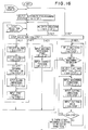
- Fig. 3 is a flowchart of a preferred example of processing for part profile input according to the present invention
- Figs. 4 through 16 are examples of conversational displays for part profile input according to the present invention.
- numeral 11 denotes an automatic programming unit
- 12 an NC control unit
- 13 a graphic display unit (CRT) 14
- keyboard a keyboard
- 16 changeover units The changeover units 15, 16 are illustrated as being switches for the sake of the description. In actuality, however, changeover is effected by software processing.
- the automatic programming unit 11 and NC control unit 12 are of microcomputer construction and incorporate an internal processor, a control program memory (ROM) and a RAM.
- the graphic display unit 13 and keyboard 14 are integrated into a single unit, as shown in Fig. 2, which is usually referred to as a CRT/MDI unit.
- the display screen is divided into a conversational display area 13a and a soft key area 13b.
- Keys 13c, 13c (see Fig. 2)... are provided to correspond to the soft key area. Pressing one of the keys enables the corresponding function displayed in the soft key area to be inputted.
- the keyboard 14 has an NC mode/automatic programming mode selection key 14a and a key group 14b, which includes keys serving as both arrow and numeric key, as well as the C key, R key and G key.
- Numeral 14c denotes an input key.
- processing up to the sixth step is executed conversationally in a manner similar to the flow of the conventional method shown in Fig. 16. If a soft key "NEXT PAGE" is pressed in the sixth step, a part profile input processing routine is started to display the part profile input screen and make possible a part profile input (see Fig. 4). Here it is determined whether it is necessary to enter a repeating shape or a standardized shape (step 101).
- the processor of the automatic programming unit 11 paints the graphic image PFG of each of the part profile elements on the display screen (CRT) along with the symbols PSF of the part profile elements.
- the operator selects "PATTERN INPUT" PIN from the soft key display 13b and presses the corresponding soft key 13c (see Fig. 2).
- the processor displays a menu for pattern profile selection shown in Fig. 5 on the soft key display 13b (step 103).
- the processor displays a groove series input screen on the display unit (CRT) (step 105; see Fig. 6).
- the groove series input screen includes a groove series pattern view CGP and a dimensions message DQS.
- EP signifies the end point of a pattern profile
- EDX the X coordinate thereof
- EZ the Z coordinate thereof
- N signifies the number of grooves
- PT signifies one groove pitch.
- DN signifies the direction of a groove, this direction being entered by an arrow key.
- WT represents groove width and DT groove depth.
- K1 - K4 signify groove corner machining. The C key is pressed for chamfering and the R key for rounding. No entry is made if corner machining is unnecessary.
- V1 - V4 signify the machining dimensions of the corners set by K1 - K4.
- the keyboard 14 is operated to key in numerical values and the like, as shown, for example, in Fig. 7, and the execute key NL is pressed (step 106).
- the processor of the automatic programming unit 11 paints the groove series profile EL4 on the screen at the end point P0 of the part profile PFG, as shown in Fig. 8. Further, the processor breaks the defined groove series profile into profile elements one at a time, calculates and stores the dimensions thereof and displays profile element symbols "G ⁇ G ⁇ G ⁇ ". In addition, the soft key display becomes the same as that shown in Fig. 4, entry of the groove series ends and entry of the next part profile becomes possible (steps 107 - 108).
- the processor displays a trapezoidal groove input screen on the display unit (CRT) (see Fig. 9).
- the trapezoidal groove input screen includes a trapezoidal groove pattern view TGP and a dimensions message DQS.
- WA signifies groove width
- MB bottom width signifies groove width
- a taper angle signifies groove depth
- K1 - K4 signify groove corner machining.
- the C key is pressed for chamfering and the R key for rounding. No entry is made if corner machining is unnecessary.
- the arrangement is such that dimensions indicated by the symbols in the pattern view TGP, as well as other data, can be set by responding to the message DQS.
- DN represents groove direction, which direction is entered by an arrow key.
- V1 - V4 signify the machining dimensions of the corners set by K1 - K4.
- the keyboard 14 is operated in response to the message DQS to key in numerical values and the like, as shown in Fig. 10, and the execute key NL is pressed.
- the processor of the automatic programming unit 11 paints the trapezoidal groove shape EL4 on the screen at the end point P0 of the part profile PFG, as shown in Fig. 11.
- the processor breaks the defined trapezoidal groove shape into profile elements one at a time, calculates and stores the dimensions thereof and displays profile element symbols "R ⁇ R ⁇ R ⁇ R".
- the soft key display becomes the same as that shown in Fig. 4, entry of the trapezoidal shape ends and entry of the next part profile becomes possible (step 201).
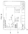
- the processor displays a nesting corner input screen on the display unit (CRT) (see Fig. 12).
- the nesting corner input screen includes a nesting corner pattern view NCP and a dimensions message DQS.
- NCP signifies nesting width, T nesting depth, R rounding and A taper angle.
- P* signifies definition of an end point.
- EDX is the X coordinate of the end point, and EZ is the Z coordinate thereof.
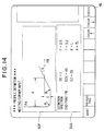
- the keyboard 14 is operated in response to the message DQS to key in numerical values and the like, as shown in Fig. 14, and the execute key NL is pressed.
- the processor of the automatic programming unit 11 paints the nesting corner shape EL4 on the screen at the end point P0 of the part profile PFG, as shown in Fig. 15.
- the processor breaks the defined nesting corner shape into profile elements one at a time, calculates and stores the dimensions thereof and displays profile element symbols " ⁇ R ⁇ R ⁇ ⁇ ".
- the soft key display becomes the same as that shown in Fig. 4, entry of the trapezoidal shape ends and entry of the next part profile becomes possible (step 301).
- a plurality of profile menus indicating repeating shapes or standardized shapes contained in a part profile are prepared, and data such as dimensions are applied to shapes selected from the profile menus to specify the repeating shape or standardized shape. Therefore, when entering a frequently used shape, the speed and operability of the part profile input operation can be improved by eliminating the laborious task of pressing arrow symbol keys and dimension input keys each time an input is made.
Landscapes
- Physics & Mathematics (AREA)
- Engineering & Computer Science (AREA)
- Geometry (AREA)
- Human Computer Interaction (AREA)
- Manufacturing & Machinery (AREA)
- General Physics & Mathematics (AREA)
- Automation & Control Theory (AREA)
- Numerical Control (AREA)
- Electrically Operated Instructional Devices (AREA)
Abstract
Description
- This invention relates to a part profile input method for entering a part profile using arrow keys.
- An automatic programming system is available in which a conversational display and a function key (soft key) display are each presented in accordance with each step of a plurality of data input steps, a specific function key (soft key) on the function key display is pressed to thereby execute processing conforming to the function, and an NC program is prepared using data inputted while referring to the conversational display.
- An automatic programming system of this kind, which will be described with reference to Fig. 16, creates NC data for a lathe by the following steps:
- (1) a first step of selecting execution of "AUTOMATIC PROGRAMMING";
- (2) a second step of selecting data to be inputted, or in other words, a step to be executed next;
- (3) a third step of selecting the material of a blank;
- (4) a fourth step of setting surface roughness;
- (5) a fifth step of selecting a drawing format;
- (6) a sixth step of inputting the blank profile and the dimensions thereof;
- (7) a seventh step of inputting a part profile and the dimensions thereof;
- (8) an eighth step of inputting the machining reference point and turret position;
- (9) a ninth step of selecting a machining process;
- (10) a tenth step of selecting a tool and inputting tool data;
- (11) an eleventh step of deciding machining conditions;
- (12) a twelfth step of inputting cutting direction;
- (13) a thirteenth step of inputting cutting limits;
- (14) a fourteenth step of inputting whether or not an area is to be cut by the same tool; and
- (15) a fifteenth step of computing a tool path (i.e. of preparing NC data).
- In accordance with these steps, predetermined message screens (conversational screens) are successively displayed on a display screen. An operator responds to these messages by entering the necessary data from a keyboard. Finally, an NC program (NC data) for a lathe is created using all of the entered data.
- In the part profile input step (the seventh step) of this automatic programming, a prompt (ES = ) calling for a part profile element is displayed on the display screen, as shown in Fig. 17. In response to this prompt, arrow keys (↑, →, ↓, ←, ↗, ↘, ↙, ↖, ↪,) a thread-cutting key, a chamfering key (C key), a rounding key (R key), a grooving key (G key) and a corner-removal key, which are provided on a keyboard, are operated in accordance with the part profile while a design drawing is observed. The part profile is thus inputted. Whenever a single part profile element is inputted using an arrow key, a prompt calling for the dimensions of this element is displayed. In response to this prompt, dimensions taken from the design drawing are inputted, whereupon profile element symbols PFS and graphic images PFG of these profile elements appear on the display screen. For example, when linear elements are inputted by pressing the arrow keys indicated by ↑, →, ↓, ←, ↗, ↘, ↙, ↖, prompts appear calling for the X coordinate (X) of the end point of the straight line, the Z coordinate (Z) of this end point, whether or not this straight line contacts the preceding profile element or the next profile element, the angle (A) which the straight line forms with the Z axis, etc. The dimensions written on the drawing are entered in response to these prompts. However, when the prescribed dimensions are not written on the drawing (as in the case of the angle formed with the Z axis, for example), this input is not required.

- When a circular arc is inputted by pressing the arrow keys indicated by ↪ and, prompts appear calling for the X and Z coordinates (X,Z) of the end point of the circular arc, the X and Z coordinates (X,Z) of the center of the circular arc, the radius R of the circular arc, and whether the arc contacts the preceding profile element or the next profile element. The dimensions written on the drawing are inputted in response to these prompts.

- When chamfering is inputted by the C key, a prompt calling for the amount of chamfering appears. When rounding is inputted by the R key, a prompt inquiring about the radius of rounding is displayed. In response, the dimensions are entered in similar fashion.
- When entry of all profile elements is completed, all of the profile element symbols PFS of the part profile and the overall part profile figure PFG are displayed on the display screen.
- In the part profile input step, there are cases where it is desired to enter a repeating shape such as a series of grooves or a standardized shape, e.g., a shape for which the machining profile is standardized as in the case of, for example, a trapezoidal groove or nesting shape. Fig. 18 is a view for entering a profile having a series of grooves. In such case, in accordance with the conventional part profile input method, an arrow key, grooving key (G key) and, if necessary, the chamfering key (C key) and rounding key (R key) provided on the keyboard must be operated for every groove, the dimensions of the elements must be entered whenever an arrow key is pressed, and the same operations must be performed repeatedly a number of times equivalent to the number of grooves.
- Also, when entering a standardized shape such as a trapezoidal groove or nesting shape, the shape must be specified on each occasion using arrow keys a number of times even though the shape is standardized and frequently appears.
- Accordingly, an object of the present invention is to provide a part profile input method in which, when entering a frequently used shape, such as a repeating shape or standardized shape, the speed and operability of the part profile input operation can be improved by eliminating the laborious task of pressing arrow symbol keys and dimension input keys each time an input is made.
- EP-A-0044192 discloses a part profile input method in an NC data creating apparatus, in which a part profile is inputted by an operator inputting successive profile elements of the part using arrow keys successively and inputting dimensions for specifying each of said profile elements, and the NC data creating apparatus creates NC data to machine a blank in accordance with said part profile inputted by the operator.
- According to the present invention which is defined by
claim 1 there is provided a plurality of profile menus designating profile patterns of repeating shapes or of standardized shapes which may be contained in a part profile; at a point in the successive inputting of said profile elements using said arrow keys the operator encounters a next portion of the part profile which is one of said profile patterns of repeating shapes or standardized shapes; at said point the operator selects said one profile pattern using said profile menus; the NC data creating apparatus displays the selected profile pattern on a display screen and displays a message calling for various dimensions; and the NC data creating apparatus specifies a repeating shape or standardized shape based on data entered by the operator in response to said message, and introduces said specified repeating shape or standardized shape into the part profile inputted by the operator. - For a better understanding of the present invention and to show how it may be put into effect reference will now be made, by way of example, to the accompanying drawings in which:
- Fig. 1 is a block diagram of an NC apparatus having an automatic programming function for realizing the method of the present invention;
- Fig. 2 is an external view of a CRT/MDI unit in the NC apparatus;
- Fig. 3 is a flowchart of part profile input processing according to a preferred example of the present invention;
- Figs. 4 and 5 are examples of conversational displays of pattern profile selection;
- Figs. 6 through 8 are examples of conversational displays for inputting a series of groove shapes;
- Figs. 9 through 11 are examples of conversational displays for inputting a trapezoidal groove shape;
- Figs. 12 through 15 are examples of conversational displays for inputting a nesting corner shape;
- Fig. 16 is a flowchart of automatic programming processing; and
- Figs. 17 and 18 are views for describing part profile input according to the prior art.
- Fig. 1 is a block diagram of an NC apparatus having an automatic programming function for realizing the present invention, Fig. 2 is an external view of a CRT/MDI unit, Fig. 3 is a flowchart of a preferred example of processing for part profile input according to the present invention, and Figs. 4 through 16 are examples of conversational displays for part profile input according to the present invention.
- In Fig. 1,
numeral 11 denotes an automatic programming unit, 12 an NC control unit, 13 a graphic display unit (CRT) 14 a keyboard, and 15, 16 changeover units. Thechangeover units - The
automatic programming unit 11 andNC control unit 12 are of microcomputer construction and incorporate an internal processor, a control program memory (ROM) and a RAM. - The
graphic display unit 13 andkeyboard 14 are integrated into a single unit, as shown in Fig. 2, which is usually referred to as a CRT/MDI unit. As shown in Fig. 1, the display screen is divided into aconversational display area 13a and asoft key area 13b. Keys 13c, 13c (see Fig. 2)... are provided to correspond to the soft key area. Pressing one of the keys enables the corresponding function displayed in the soft key area to be inputted. Thekeyboard 14 has an NC mode/automatic programmingmode selection key 14a and akey group 14b, which includes keys serving as both arrow and numeric key, as well as the C key, R key and G key. Numeral 14c denotes an input key. - Part profile input according to the invention will now be described.
- The operator operates the
key 14a (Fig. 2) on thekeyboard 14 to cause thechangeover units graphic display unit 13 andkeyboard 14 to theautomatic programming unit 11. Thereafter, in accordance with the programming function of theautomatic programming unit 11, processing up to the sixth step is executed conversationally in a manner similar to the flow of the conventional method shown in Fig. 16. If a soft key "NEXT PAGE" is pressed in the sixth step, a part profile input processing routine is started to display the part profile input screen and make possible a part profile input (see Fig. 4). Here it is determined whether it is necessary to enter a repeating shape or a standardized shape (step 101). - If it is unnecessary to enter these shapes, the operator, in response to a prompt (ES = ) regarding a part profile element displayed on the display screen, enters a part profile (step 102) by operating the arrow keys (↑, →, ↓, ← etc.) provided on the keyboard while observing a design drawing. Specifically, the operator presses the arrow key "→" in conformity with one part profile element EL₁ and, in response to a prompt calling for dimensions, enters dimensions from the design drawing. Similarly, the operator presses the arrow keys "↓, →" in conformity with part profile elements EL₂, EL₃ and enters dimensions in response to prompts calling for the respective dimensions. In response to entry of these part profile elements, the processor of the
automatic programming unit 11 paints the graphic image PFG of each of the part profile elements on the display screen (CRT) along with the symbols PSF of the part profile elements. - If it becomes necessary to enter a repeating shape or a standardized shape, the operator selects "PATTERN INPUT" PIN from the soft
key display 13b and presses the corresponding soft key 13c (see Fig. 2). In response, the processor displays a menu for pattern profile selection shown in Fig. 5 on the softkey display 13b (step 103). - Examples of entering "GROOVE SERIES", "TRAPEZOIDAL GROOVE" and "NESTING CORNER" part profiles will now be described.
- When "GROOVE SERIES WITH EQUAL PITCH" is selected in Fig. 5 (step 104), the processor displays a groove series input screen on the display unit (CRT) (
step 105; see Fig. 6). It should be noted that the groove series input screen includes a groove series pattern view CGP and a dimensions message DQS. - In the groove series pattern view CGP, EP signifies the end point of a pattern profile, EDX the X coordinate thereof, and EZ the Z coordinate thereof. N signifies the number of grooves, and PT signifies one groove pitch. These numerical values are entered. DN signifies the direction of a groove, this direction being entered by an arrow key. WT represents groove width and DT groove depth. K₁ - K₄ signify groove corner machining. The C key is pressed for chamfering and the R key for rounding. No entry is made if corner machining is unnecessary.
- The arrangement is such that dimensions indicated by the symbols in the pattern view CGP, as well as other data, can be set by responding to the message DQS. V₁ - V₄ signify the machining dimensions of the corners set by K₁ - K₄.
- The distance from the end point P₀ of a preceding profile element to the end point EP of the pattern profile need not be equal to an N multiple of the pitch PT; the pitch of the final groove will change depending upon the set value of the end point EP. However, it is required that the following equation be satisfied if the grooves are lined up parallel to the Z axis:

and that the following equation be satisfied if the grooves are lined up parallel to the X axis:
If these equations are not satisfied, an error will result. SZ and SDX signify the Z and X coordinates of the end point P₀ of the preceding element, respectively. - In response to the message DQS, the
keyboard 14 is operated to key in numerical values and the like, as shown, for example, in Fig. 7, and the execute key NL is pressed (step 106). - When this is done, the processor of the
automatic programming unit 11 paints the groove series profile EL₄ on the screen at the end point P₀ of the part profile PFG, as shown in Fig. 8. Further, the processor breaks the defined groove series profile into profile elements one at a time, calculates and stores the dimensions thereof and displays profile element symbols "G → G → G →". In addition, the soft key display becomes the same as that shown in Fig. 4, entry of the groove series ends and entry of the next part profile becomes possible (steps 107 - 108). - If "TRAPEZOIDAL GROOVE" is selected in Fig. 5, the processor displays a trapezoidal groove input screen on the display unit (CRT) (see Fig. 9). It should be noted that the trapezoidal groove input screen includes a trapezoidal groove pattern view TGP and a dimensions message DQS. In the trapezoidal groove pattern view TGP, WA signifies groove width, MB bottom width, A taper angle, and DT groove depth. K₁ - K₄ signify groove corner machining. The C key is pressed for chamfering and the R key for rounding. No entry is made if corner machining is unnecessary.
- The arrangement is such that dimensions indicated by the symbols in the pattern view TGP, as well as other data, can be set by responding to the message DQS. DN represents groove direction, which direction is entered by an arrow key. V₁ - V₄ signify the machining dimensions of the corners set by K₁ - K₄.
- By way of example, the
keyboard 14 is operated in response to the message DQS to key in numerical values and the like, as shown in Fig. 10, and the execute key NL is pressed. When this is done, the processor of theautomatic programming unit 11 paints the trapezoidal groove shape EL₄ on the screen at the end point P₀ of the part profile PFG, as shown in Fig. 11. Further, the processor breaks the defined trapezoidal groove shape into profile elements one at a time, calculates and stores the dimensions thereof and displays profile element symbols "R ↘ R → R ↗ R". In addition, the soft key display becomes the same as that shown in Fig. 4, entry of the trapezoidal shape ends and entry of the next part profile becomes possible (step 201). - If "NESTING CORNER" is selected in Fig. 5, the processor displays a nesting corner input screen on the display unit (CRT) (see Fig. 12). The nesting corner input screen includes a nesting corner pattern view NCP and a dimensions message DQS. In the pattern view NCP, F signifies nesting width, T nesting depth, R rounding and A taper angle.
- The arrangement is such that dimensions indicated by the symbols in the pattern view NCP, as well as other data, can be set by responding to the message DQS. DD signifies the nesting shape definition direction, which direction is entered by an arrow key. If, as shown in Fig. 13(a), point PA is taken as the starting point and nesting corners NC₁ - NC₄ are inserted in profile entry for arriving at any of points PB₁ - PB₄, then "DD = 1" is entered. Conversely, if, as shown in Fig. 13(b), point PB is taken as the starting point and nesting corners NC₁′ - NC₄′ are inserted in profile input for arriving at any of points PA₁ - PA₄, then"DD = 2" is entered. In the message DQS, P* signifies definition of an end point. In case of "DD = 1", * is displayed with B; in case of "DD = 2", * is displayed with A. EDX is the X coordinate of the end point, and EZ is the Z coordinate thereof.
- By way of example, the
keyboard 14 is operated in response to the message DQS to key in numerical values and the like, as shown in Fig. 14, and the execute key NL is pressed. When this is done, the processor of theautomatic programming unit 11 paints the nesting corner shape EL₄ on the screen at the end point P₀ of the part profile PFG, as shown in Fig. 15. Further, the processor breaks the defined nesting corner shape into profile elements one at a time, calculates and stores the dimensions thereof and displays profile element symbols "↓ R → R ↗ →". In addition, the soft key display becomes the same as that shown in Fig. 4, entry of the trapezoidal shape ends and entry of the next part profile becomes possible (step 301). - In a case where a profile element entered by the foregoing method is revised or deleted, this is performed one element at a time just as in the conventional method. When entry of a part profile ends (step 109), the soft key "NEXT PAGE" is pressed to display the next conversional screen, after which automatic programming processing is resumed.
- In accordance with the present invention as described above, a plurality of profile menus indicating repeating shapes or standardized shapes contained in a part profile are prepared, and data such as dimensions are applied to shapes selected from the profile menus to specify the repeating shape or standardized shape. Therefore, when entering a frequently used shape, the speed and operability of the part profile input operation can be improved by eliminating the laborious task of pressing arrow symbol keys and dimension input keys each time an input is made.
Claims (7)
- A part profile input method in an NC data creating apparatus (11, 13, 14), in which a part profile is inputted by an operator inputting successive profile elements (EL) of the part using arrow keys (14b) successively and inputting dimensions for specifying each of said profile elements (EL), and the NC data creating apparatus (11, 13, 14) creates NC data to machine a blank in accordance with said part profile inputted by the operator, characterised in that:
there is provided a plurality of profile menus designating profile patterns of repeating shapes or of standardized shapes which may be contained in a part profile;
at a point (P₀) in the successive inputting of said profile elements (EL) using said arrow keys (146) the operator encounters a next portion of the part profile which is one of said profile patterns of repeating shapes or standardized shapes;
at said point (P₀) the operator selects said one profile pattern using said profile menus;
the NC data creating apparatus (11, 13, 14) displays the selected profile pattern on a display screen (13) and displays a message calling for various dimensions; and
the NC data creating apparatus (11, 13, 14) specifies a repeating shape or standardized shape based on data entered by the operator in response to said message, and introduces said specified repeating shape or standardized shape into the part profile inputted by the operator. - A part profile input method according to claim 1, wherein the NC data creating apparatus breaks said inputted repeating shape or standardized shape into separate profile elements, calculates dimensions thereof and stores the dimensions.
- A part profile input method according to claim 1 or 2, wherein whenever a profile element (EL) is inputted, said profile element (EL) is displayed in a form attached to a part profile inputted thus far, and when a repeating shape or standardized shape is inputted, this shape is displayed in a form attached to a part profile inputted thus far.
- A part profile input method according to any preceding claim, wherein said plurality of profile menus are displayed on a first conversational screen (Fig. 5), which is for inputting a part profile, for every profile element (EL);
when a desired profile pattern is selected using said profile menus, a second conversational screen (Fig. 6, 9 or 12) is displayed, which includes a display of the profile pattern and a dimensions message, instead of said first conversational screen (Fig. 5); and
when a shape is designated on said second conversational screen (Fig. 6, 9 or 12) by entering necessary data, a return is effected to the first conversational screen and said designated shape is displayed in a form attached to the part profile inputted so far (Fig. 8, 11 or 15). - A part profile input method according to any preceding claim, wherein said designated profile patterns comprise a repeated shape which is a series of grooves.
- A part profile input method according to any preceding claim, wherein said designated profile patterns comprise a standardized shape which is a trapezoidal groove.
- A part profile input method according to any preceding claim, wherein said designated profile patterns comprises a standardized shape which is a nesting corner shape.
Applications Claiming Priority (3)
| Application Number | Priority Date | Filing Date | Title |
|---|---|---|---|
| JP3193/88 | 1987-12-17 | ||
| JP62319388A JPH01159705A (en) | 1987-12-17 | 1987-12-17 | Parts shape inputting method |
| PCT/JP1988/001260 WO1989006004A1 (en) | 1987-12-17 | 1988-12-13 | Method of inputting part profile |
Publications (3)
| Publication Number | Publication Date |
|---|---|
| EP0348522A1 EP0348522A1 (en) | 1990-01-03 |
| EP0348522A4 EP0348522A4 (en) | 1993-06-09 |
| EP0348522B1 true EP0348522B1 (en) | 1995-08-30 |
Family
ID=18109609
Family Applications (1)
| Application Number | Title | Priority Date | Filing Date |
|---|---|---|---|
| EP89900321A Expired - Lifetime EP0348522B1 (en) | 1987-12-17 | 1988-12-13 | Method of inputting part profile |
Country Status (5)
| Country | Link |
|---|---|
| US (1) | US5089950A (en) |
| EP (1) | EP0348522B1 (en) |
| JP (1) | JPH01159705A (en) |
| DE (1) | DE3854390T2 (en) |
| WO (1) | WO1989006004A1 (en) |
Families Citing this family (21)
| Publication number | Priority date | Publication date | Assignee | Title |
|---|---|---|---|---|
| JPH02101506A (en) * | 1988-10-08 | 1990-04-13 | Fanuc Ltd | Shape input system |
| JPH084992B2 (en) * | 1989-12-13 | 1996-01-24 | オ−クマ株式会社 | Grooving method decision method in numerical control information creation function |
| JP2993158B2 (en) * | 1990-04-05 | 1999-12-20 | 三菱電機株式会社 | Numerical control unit |
| JP2511166Y2 (en) * | 1990-06-25 | 1996-09-18 | 豊田工機株式会社 | Shape data input device |
| EP0503642B1 (en) * | 1991-03-15 | 1997-06-11 | Spatial Technology, Inc. | Method and apparatus for solids-based machining |
| JPH05197411A (en) * | 1992-01-20 | 1993-08-06 | Fanuc Ltd | Work program generation method |
| DE4240890C2 (en) * | 1992-02-17 | 1996-09-26 | Mitsubishi Electric Corp | CAD device for generating an NC program |
| US6219055B1 (en) * | 1995-12-20 | 2001-04-17 | Solidworks Corporation | Computer based forming tool |
| DE19614130C2 (en) * | 1996-04-10 | 2002-11-21 | Agie Sa | Method and device for controlling a machine tool, in particular a spark erosion machine |
| GB2350207B (en) * | 1999-05-11 | 2003-08-20 | Falcon Machine Tools Co Ltd | Interactive system between machine tool and operator |
| GB2350442A (en) * | 1999-05-18 | 2000-11-29 | Falcon Machine Tools Co Ltd | Computerised numerical controller with profile path editor |
| CA2747118C (en) * | 2005-03-23 | 2015-02-10 | Hurco Companies, Inc. | Method of curvature controlled data smoothing |
| US8725283B2 (en) * | 2006-08-04 | 2014-05-13 | Hurco Companies, Inc. | Generalized kinematics system |
| WO2008019340A2 (en) * | 2006-08-04 | 2008-02-14 | Hurco Companies, Inc. | System and method for tool use management |
| US7933677B2 (en) * | 2006-08-04 | 2011-04-26 | Hurco Companies, Inc. | System and method for surface finish management |
| US8024068B2 (en) | 2006-08-04 | 2011-09-20 | Hurco Companies, Inc. | Machine tool control system |
| USD582925S1 (en) * | 2007-09-17 | 2008-12-16 | Sap Ag | Display panel with a computer-generated icon |
| USD582931S1 (en) * | 2007-09-17 | 2008-12-16 | Sap Ag | Display panel with a computer-generated icon |
| USD592218S1 (en) * | 2007-09-17 | 2009-05-12 | Sap Ag | Display panel with a computer-generated icon |
| USD582923S1 (en) * | 2007-09-17 | 2008-12-16 | Sap Ag | Display panel with a computer-generated icon |
| USD582926S1 (en) * | 2007-09-17 | 2008-12-16 | Sap Ag | Display panel with a transitional computer-generated icon |
Citations (2)
| Publication number | Priority date | Publication date | Assignee | Title |
|---|---|---|---|---|
| EP0044192A1 (en) * | 1980-07-10 | 1982-01-20 | Fanuc Ltd. | A method for preparing numerical control information |
| EP0078856A1 (en) * | 1981-05-18 | 1983-05-18 | Fanuc Ltd. | Numerical control device |
Family Cites Families (6)
| Publication number | Priority date | Publication date | Assignee | Title |
|---|---|---|---|---|
| JPS57121443A (en) * | 1981-01-20 | 1982-07-28 | Okuma Mach Works Ltd | Data input method for numerical control system |
| JPS58163001A (en) * | 1982-03-23 | 1983-09-27 | Toyoda Mach Works Ltd | Numerical controller equipped with interference checking function |
| DE3608438A1 (en) * | 1985-03-13 | 1986-09-18 | Toshiba Kikai K.K., Tokio/Tokyo | METHOD FOR CALCULATING FREE CURVED SURFACES BY MEANS OF COMPUTER-AID DESIGN CAD AND COMPUTER-AID MANUFACTURING CAM AND NUMERICAL CONTROL NC |
| JPS61255408A (en) * | 1985-05-07 | 1986-11-13 | Hitachi Seiki Co Ltd | Device for inputting list of work form |
| JPS63250707A (en) * | 1987-04-07 | 1988-10-18 | Fanuc Ltd | Method for inputting part shape |
| US4928221A (en) * | 1988-04-11 | 1990-05-22 | Westinghouse Electric Corp. | Part program generating system |
-
1987
- 1987-12-17 JP JP62319388A patent/JPH01159705A/en active Pending
-
1988
- 1988-12-13 US US07/397,455 patent/US5089950A/en not_active Expired - Fee Related
- 1988-12-13 WO PCT/JP1988/001260 patent/WO1989006004A1/en not_active Ceased
- 1988-12-13 EP EP89900321A patent/EP0348522B1/en not_active Expired - Lifetime
- 1988-12-13 DE DE3854390T patent/DE3854390T2/en not_active Expired - Fee Related
Patent Citations (3)
| Publication number | Priority date | Publication date | Assignee | Title |
|---|---|---|---|---|
| EP0044192A1 (en) * | 1980-07-10 | 1982-01-20 | Fanuc Ltd. | A method for preparing numerical control information |
| JPS5719809A (en) * | 1980-07-10 | 1982-02-02 | Fanuc Ltd | Numerical control information generating system |
| EP0078856A1 (en) * | 1981-05-18 | 1983-05-18 | Fanuc Ltd. | Numerical control device |
Non-Patent Citations (1)
| Title |
|---|
| PATENT ABSTRACTS OF JAPAN vol. 10, no. 22 (P-424)(2079) 28 January 1986 & JP-A-60 176 107 * |
Also Published As
| Publication number | Publication date |
|---|---|
| WO1989006004A1 (en) | 1989-06-29 |
| EP0348522A1 (en) | 1990-01-03 |
| DE3854390D1 (en) | 1995-10-05 |
| DE3854390T2 (en) | 1996-02-08 |
| EP0348522A4 (en) | 1993-06-09 |
| US5089950A (en) | 1992-02-18 |
| JPH01159705A (en) | 1989-06-22 |
Similar Documents
| Publication | Publication Date | Title |
|---|---|---|
| EP0348522B1 (en) | Method of inputting part profile | |
| EP0303705B1 (en) | Method of entering profile information | |
| US4490781A (en) | System and method for preparing numerical control information | |
| EP0078856B2 (en) | Numerical control device | |
| US5177689A (en) | Cad/cam apparatus for enhancing operator entry of machining attributes and geometric shapes | |
| US4788636A (en) | Interactive device for entering graphic data | |
| EP0034506A2 (en) | Image display system | |
| US4901220A (en) | Part profile input method | |
| EP0247204B1 (en) | Interactive programming device | |
| US4891763A (en) | NC program editing and programming device | |
| EP0348533B1 (en) | Automatic programming method | |
| US5099432A (en) | Method for determining machining process in numerical control information generating function | |
| EP0079388B1 (en) | A numerical control method | |
| EP0144428B1 (en) | Method of discriminating angle data | |
| US5029068A (en) | NC data creation method | |
| US5072398A (en) | Figure definition method in automatic programming | |
| US5146402A (en) | Profile definition method | |
| JPH06202721A (en) | Numerical control information generating device | |
| EP0165999A1 (en) | Tool-selecting method for automatic programming | |
| US5063517A (en) | Profile revising method | |
| EP0148947A1 (en) | Data input method | |
| EP0332703A1 (en) | Data input system | |
| EP0519077A1 (en) | Conversational type numerical control device | |
| EP0530364A1 (en) | Interactive numerical controller | |
| EP0453570A1 (en) | Nc program preparation method of interactive numeric controller or automatic programming apparatus |
Legal Events
| Date | Code | Title | Description |
|---|---|---|---|
| PUAI | Public reference made under article 153(3) epc to a published international application that has entered the european phase |
Free format text: ORIGINAL CODE: 0009012 |
|
| 17P | Request for examination filed |
Effective date: 19890831 |
|
| AK | Designated contracting states |
Kind code of ref document: A1 Designated state(s): DE FR GB |
|
| A4 | Supplementary search report drawn up and despatched |
Effective date: 19930420 |
|
| AK | Designated contracting states |
Kind code of ref document: A4 Designated state(s): DE FR GB |
|
| 17Q | First examination report despatched |
Effective date: 19940610 |
|
| GRAA | (expected) grant |
Free format text: ORIGINAL CODE: 0009210 |
|
| AK | Designated contracting states |
Kind code of ref document: B1 Designated state(s): DE FR GB |
|
| PG25 | Lapsed in a contracting state [announced via postgrant information from national office to epo] |
Ref country code: FR Free format text: THE PATENT HAS BEEN ANNULLED BY A DECISION OF A NATIONAL AUTHORITY Effective date: 19950830 |
|
| REF | Corresponds to: |
Ref document number: 3854390 Country of ref document: DE Date of ref document: 19951005 |
|
| PG25 | Lapsed in a contracting state [announced via postgrant information from national office to epo] |
Ref country code: GB Effective date: 19951213 |
|
| PGFP | Annual fee paid to national office [announced via postgrant information from national office to epo] |
Ref country code: DE Payment date: 19951214 Year of fee payment: 8 |
|
| EN | Fr: translation not filed | ||
| PLBE | No opposition filed within time limit |
Free format text: ORIGINAL CODE: 0009261 |
|
| STAA | Information on the status of an ep patent application or granted ep patent |
Free format text: STATUS: NO OPPOSITION FILED WITHIN TIME LIMIT |
|
| GBPC | Gb: european patent ceased through non-payment of renewal fee |
Effective date: 19951213 |
|
| 26N | No opposition filed | ||
| PG25 | Lapsed in a contracting state [announced via postgrant information from national office to epo] |
Ref country code: DE Effective date: 19970902 |