EP0348248B1 - Form für die Herstellung eines metallischen Gegenstandes, Gebrauch dieser Form und Verfahren zur entsprechenden Formherstellung - Google Patents
Form für die Herstellung eines metallischen Gegenstandes, Gebrauch dieser Form und Verfahren zur entsprechenden Formherstellung Download PDFInfo
- Publication number
- EP0348248B1 EP0348248B1 EP19890401144 EP89401144A EP0348248B1 EP 0348248 B1 EP0348248 B1 EP 0348248B1 EP 19890401144 EP19890401144 EP 19890401144 EP 89401144 A EP89401144 A EP 89401144A EP 0348248 B1 EP0348248 B1 EP 0348248B1
- Authority
- EP
- European Patent Office
- Prior art keywords
- mould
- moulding
- denseners
- moulding box
- densener
- Prior art date
- Legal status (The legal status is an assumption and is not a legal conclusion. Google has not performed a legal analysis and makes no representation as to the accuracy of the status listed.)
- Expired - Lifetime
Links
- 238000000465 moulding Methods 0.000 title claims description 36
- 238000000034 method Methods 0.000 title claims description 10
- 238000004519 manufacturing process Methods 0.000 title claims description 9
- 239000004576 sand Substances 0.000 claims description 10
- 238000010791 quenching Methods 0.000 claims description 9
- 238000001816 cooling Methods 0.000 claims description 8
- 230000000171 quenching effect Effects 0.000 claims description 8
- 229910001018 Cast iron Inorganic materials 0.000 claims description 7
- 229910000831 Steel Inorganic materials 0.000 claims description 6
- 239000010959 steel Substances 0.000 claims description 6
- 238000005266 casting Methods 0.000 claims description 4
- 239000000463 material Substances 0.000 claims description 4
- 239000007769 metal material Substances 0.000 claims description 3
- 229910001338 liquidmetal Inorganic materials 0.000 claims 2
- 238000007711 solidification Methods 0.000 claims 1
- 230000008023 solidification Effects 0.000 claims 1
- 239000002184 metal Substances 0.000 description 8
- 229910052751 metal Inorganic materials 0.000 description 8
- 230000015572 biosynthetic process Effects 0.000 description 4
- 239000003110 molding sand Substances 0.000 description 4
- XEEYBQQBJWHFJM-UHFFFAOYSA-N Iron Chemical compound [Fe] XEEYBQQBJWHFJM-UHFFFAOYSA-N 0.000 description 3
- 238000000227 grinding Methods 0.000 description 3
- 238000009434 installation Methods 0.000 description 3
- 238000011084 recovery Methods 0.000 description 3
- 239000007788 liquid Substances 0.000 description 2
- 229910000851 Alloy steel Inorganic materials 0.000 description 1
- 229910001037 White iron Inorganic materials 0.000 description 1
- 230000000712 assembly Effects 0.000 description 1
- 238000000429 assembly Methods 0.000 description 1
- 229910052742 iron Inorganic materials 0.000 description 1
- 238000002844 melting Methods 0.000 description 1
- 230000008018 melting Effects 0.000 description 1
- 230000002093 peripheral effect Effects 0.000 description 1
- 238000002360 preparation method Methods 0.000 description 1
- 239000011347 resin Substances 0.000 description 1
- 229920005989 resin Polymers 0.000 description 1
Images

Classifications
-
- B—PERFORMING OPERATIONS; TRANSPORTING
- B22—CASTING; POWDER METALLURGY
- B22D—CASTING OF METALS; CASTING OF OTHER SUBSTANCES BY THE SAME PROCESSES OR DEVICES
- B22D27/00—Treating the metal in the mould while it is molten or ductile ; Pressure or vacuum casting
- B22D27/04—Influencing the temperature of the metal, e.g. by heating or cooling the mould
Definitions
- the invention relates to a mold comprising coolers for the manufacture of a metal part having at least one surface area hardened by quenching during the molding according to the preamble of claim 1, a molding method according to the preamble of claim 11 and the use of this mold for the manufacture of camshafts.
- Parts are known, in particular parts used in the automotive industry, such as camshafts, which have certain zones whose surface hardness is higher than the hardness of the other parts of the part.
- the sand molding of the part is carried out in an imprint formed inside the sand filling a hollow metal frame which generally consists of several parts. Rapid cooling or quenching of the cast iron is provided in the areas of the cavity corresponding to the periphery of the cams by metal coolers flush with the surface of the cavity.
- the coolers have a surface intended to come into contact with the liquid iron, the shape of which corresponds to that of at least part of the external surface of the cam.
- the mold is generally made up of two superimposable half-molds which each have a cavity corresponding to a half-cavity of the part.
- the coolers are either made up of separate parts or connected together to form clusters of several coolers.
- each of the coolers corresponds to half of the periphery of a cam and must be placed in a semi-mold produced beforehand.
- the cluster of coolers is placed on the model plate before the half-mold is produced.
- the coolers constitute independent elements which it is necessary to place very precisely in the mold before or after filling it with sand and before each casting.
- the coolers are removed with the sand from which they are collected.
- the coolers must be sorted since they are not all identical, then prepared for the next molding operation.
- the object of the invention is therefore to propose a mold for the manufacture of a metal part having at least one surface area hardened by quenching during molding, comprising a hollow metal frame containing molding sand delimiting the imprint of the part and at least one cooler made of a metallic material placed in the molding sand and flush with the surface of the imprint in a part of this imprint corresponding to the hardened area of the part, this mold making it possible to avoid long and costly operations installation and recovery of coolers.
- the cooler is integral with the chassis.
- the mold according to the invention consists of a lower half-mold 1 shown in FIG. 1 and an upper half-mold 2 shown in FIG. 2.
- the lower half-mold 1 comprises a half-frame 3 with a rectangular section and the upper half-mold 2 a half-frame 4, also with a rectangular section, the sections of the half-frames 3 and 4 being perfectly superimposable.
- the steel half-frames 3 and 4 produced in hollow form, are filled with sand 5 in which two half-cavities 6, 6 ′ have been made for the molding of two camshafts of motor vehicles.
- a cavity 7 communicating with the cavities 6, 6 'to constitute a metal reserve counterweight intended to compensate for shrinkage during molding as well as a filling cup 8 passing through the half-mold upper 2 over its entire thickness.
- a runner 9 is provided in the lower half-mold 1 in accordance with the end of the filling cup 8.
- Metal coolers 10 generally constituted by steel plates are arranged in the lower half-mold 1 and in the upper half-mold 2, in corresponding positions, at the molding zones of the cams of the cavities 6 and 6 ′ of the two camshafts.
- the coolers 10 comprise cooling surfaces 13 flush with the surface of the cavities 6 and 6 ′ in zones corresponding to the peripheral part of the cams which it is desired to ensure quenching during molding.
- the coolers 10 according to the invention are fixed to the corresponding half-chassis 3 and 4, of which they remain integral during all the stages of the molding process.
- Each of the coolers 10 consists of a steel plate having two recesses intended to constitute the cooling surfaces 13 at the periphery of the cam molding zones.
- the coolers 10 are arranged transversely inside the half-chassis 3 and 4 between the two long sides of these half-chassis.
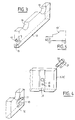
- the coolers 10 have a length, in the transverse direction, slightly greater than the internal width of the half-chassis and the corresponding sides of the half-chassis 3 and 4 have assembly grooves 14 (FIG. 4) in which come engage the ends of the coolers 10 during assembly.
- the sides of the half-frames 3 and 4 are drilled at the bottom of grooves 14 with two holes 15 and 16 and the coolers 10 have, on each of their lateral sides, engaging in the grooves 14, a tapped hole 17 and a smooth hole 18.
- the assembly and positioning of the cooler are ensured on each of its lateral sides by a screw 20 and a pin 21.
- the pin 21, engaged in the holes 16 and 18 in concordance, ensures the positioning of the cooler in the groove 14 and the screw 20, engaged in the opening 15 and screwed in the threaded hole 17, ensures the assembly of the cooler 10 on the half chassis.
- FIG 5 there is shown a cooler 10 'according to an alternative embodiment comprising a recess 13' of reduced amplitude.
- the recesses 13 'of the corresponding coolers 10' surround only part of the periphery of the cam, which makes it possible to quench and harden only part of the cam .
- the coolers 10 ′ are fixed to the corresponding half-chassis by means of their lateral sides of reduced height in which are tapped holes 17 ′.
- the mold frame may for example be made of ordinary steel and the coolers made of alloy steel or any other metallic material.
- half-molds 1 and 2 formed by the half-chassis and the coolers fixed to these half-chassis.
- the manufacture of the mold is carried out by placing each of the half-chassis on the corresponding model plate and by filling the half-chassis with molding sand. It is therefore not necessary to carry out, during this operation, the installation and adjustment of the coolers which are integral with the half-chassis.
- the mold is then assembled by superimposing the two half-molds 1 and 2, then the mold is filled by the cup 8.
- the castings are then cooled to a temperature of between 700 and 800 ° before demolding is carried out by unhooking the mold.
- the half-molds 1 and 2 are then ready for a new molding operation.
- the coolers being integral with the chassis of the half-molds, it is not necessary to carry out, as in the prior art, the recovery of the coolers in the molding sand, the sorting of these coolers and then the placing of these in the mold.
- chassis-cooler assemblies are cooled after release by an air flow to bring the half-molds to a temperature enabling the mold preparation operations to be carried out.
- the coolers are then at a temperature of about 200 ° C. Cooling by an air flow at 10 ° C allows the temperature of these chillers to be brought to a temperature which can be between 30 and 50 ° C in a very short time.
- coolers are detachably linked to the chassis, for example a forecourt, these coolers can be replaced in the event of wear.
- the cooler and the mold frame can be made of different materials.
- the invention applies regardless of the number of parts which are cast in a mold and whatever the extent of the surface to be quenched at the periphery of these parts.
- the invention applies as well in the case of conventional foundry as in the case where the lost model process (PMP) is used.
- PMP lost model process
- the invention applies not only to the molding of camshafts but also to the molding of other cast iron parts or even to the molding of metal parts made of materials other than cast iron, which can be hardened by rapid cooling or quenching. certain areas during molding.
Landscapes
- Engineering & Computer Science (AREA)
- Mechanical Engineering (AREA)
- Molds, Cores, And Manufacturing Methods Thereof (AREA)
- Valve-Gear Or Valve Arrangements (AREA)
Claims (13)
Applications Claiming Priority (2)
| Application Number | Priority Date | Filing Date | Title |
|---|---|---|---|
| FR8808541 | 1988-06-24 | ||
| FR8808541A FR2633206B1 (fr) | 1988-06-24 | 1988-06-24 | Moule pour la fabrication d'une piece metallique, utilisation de ce moule et procede de moulage correspondant |
Publications (2)
| Publication Number | Publication Date |
|---|---|
| EP0348248A1 EP0348248A1 (de) | 1989-12-27 |
| EP0348248B1 true EP0348248B1 (de) | 1992-07-01 |
Family
ID=9367709
Family Applications (1)
| Application Number | Title | Priority Date | Filing Date |
|---|---|---|---|
| EP19890401144 Expired - Lifetime EP0348248B1 (de) | 1988-06-24 | 1989-04-21 | Form für die Herstellung eines metallischen Gegenstandes, Gebrauch dieser Form und Verfahren zur entsprechenden Formherstellung |
Country Status (4)
| Country | Link |
|---|---|
| EP (1) | EP0348248B1 (de) |
| DE (1) | DE68901957T2 (de) |
| ES (1) | ES2033535T3 (de) |
| FR (1) | FR2633206B1 (de) |
Families Citing this family (1)
| Publication number | Priority date | Publication date | Assignee | Title |
|---|---|---|---|---|
| DE4431713C2 (de) * | 1994-09-06 | 2001-03-15 | Audi Ag | Vorrichtung zum Herstellen von Gußstücken |
Family Cites Families (3)
| Publication number | Priority date | Publication date | Assignee | Title |
|---|---|---|---|---|
| CH577864A5 (de) * | 1974-05-29 | 1976-07-30 | Sulzer Ag | |
| DE2646060A1 (de) * | 1976-10-13 | 1978-04-20 | Friedhelm Prof Dr Ing Kahn | Verfahren und vorrichtungen zur steuerung des waermehaushalts von giessformen |
| CH650430A5 (de) * | 1980-08-29 | 1985-07-31 | Fischer Georg Gmbh | Verfahren zum giessen von metallen mittels phenolharzgebundenen sandformen. |
-
1988
- 1988-06-24 FR FR8808541A patent/FR2633206B1/fr not_active Expired - Fee Related
-
1989
- 1989-04-21 EP EP19890401144 patent/EP0348248B1/de not_active Expired - Lifetime
- 1989-04-21 DE DE1989601957 patent/DE68901957T2/de not_active Expired - Lifetime
- 1989-04-21 ES ES89401144T patent/ES2033535T3/es not_active Expired - Lifetime
Also Published As
| Publication number | Publication date |
|---|---|
| DE68901957D1 (de) | 1992-08-06 |
| FR2633206A1 (fr) | 1989-12-29 |
| EP0348248A1 (de) | 1989-12-27 |
| FR2633206B1 (fr) | 1990-10-12 |
| ES2033535T3 (es) | 1993-03-16 |
| DE68901957T2 (de) | 1992-12-10 |
Similar Documents
| Publication | Publication Date | Title |
|---|---|---|
| EP2869986B1 (de) | Form zum formen eines kraftfahrzeugbauteils aus einem polymermaterial | |
| JP4439621B2 (ja) | ねじ部割り型インサートの製造方法 | |
| FR2554029A1 (fr) | Procede de preparation d'un materiau composite renforce de fibres | |
| WO2009112725A1 (fr) | Procede de fabrication de plaques de metal, seul ou en alliage homogene, par centrifugation | |
| EP0066261A1 (de) | Verfahren zur Herstellung eines organischen Isolators | |
| EP0348248B1 (de) | Form für die Herstellung eines metallischen Gegenstandes, Gebrauch dieser Form und Verfahren zur entsprechenden Formherstellung | |
| JP2004058098A (ja) | 鋳造用金型 | |
| FR2809705A1 (fr) | Porte d'avion et moule pour sa fabrication | |
| JP6895547B2 (ja) | 樹脂成形品及び樹脂成形品の成形方法 | |
| JPH1157975A (ja) | ダイカスト機の鋳込み装置 | |
| EP0586314B1 (de) | Verfahren zum Herstellen von Stücken aus Gusslegierungen mit verstärkten Teilen | |
| EP1099499B1 (de) | Verfahren zur Beschickung mit Giessmaterial bei Gussstücken mit Einsatz | |
| EP2158986A1 (de) | Präzisionsgussverfahren und verlorenes Modell für dieses Verfahren | |
| JPH07204782A (ja) | アルミニウム製金型 | |
| EP0693362B1 (de) | Verfahren zur Herstellung von Gegenständen aus wenigstens zwei thermoplastischen Materialien | |
| EP0301928A1 (de) | Vorrichtung und Verfahren zum Giessen auf eine Schreckplatte in eine Binderfreie Sandform mit vergasbarem Modell | |
| EP4467317A1 (de) | Formeinsatz zum spritzgiessen, form zum spritzgiessen und verfahren zur herstellung eines formeinsatzes zum spritzgiessen | |
| CN111558693A (zh) | 一种避免零件厚大部位表面制壳开裂的方法 | |
| FR2558408A1 (fr) | Porte-moule en fonte, notamment en fonte a graphite spheroidal, pour le dispositif de fermeture de moule d'une machine a mouler des matieres plastiques par injection | |
| FR3036048A1 (fr) | Procede de fonderie avec moule permanent | |
| FR2483275A1 (fr) | Procede pour la fabrication en serie, par coulee unique, d'elements de machines pourvus de cages de protection solidaires de ces elements | |
| JPH06234055A (ja) | 高硬度アルミ鋳造品の製造方法 | |
| BE391896A (de) | ||
| EP1245308A1 (de) | Verfahren und Vorrichtung zur Herstellung eines Kerns aus Sand für Giessereiformen | |
| EP4452543A1 (de) | Form zum aluminothermischen schweissen von schienen |
Legal Events
| Date | Code | Title | Description |
|---|---|---|---|
| PUAI | Public reference made under article 153(3) epc to a published international application that has entered the european phase |
Free format text: ORIGINAL CODE: 0009012 |
|
| AK | Designated contracting states |
Kind code of ref document: A1 Designated state(s): DE ES GB IT |
|
| 17P | Request for examination filed |
Effective date: 19891114 |
|
| 17Q | First examination report despatched |
Effective date: 19910912 |
|
| GRAA | (expected) grant |
Free format text: ORIGINAL CODE: 0009210 |
|
| AK | Designated contracting states |
Kind code of ref document: B1 Designated state(s): DE ES GB IT |
|
| REF | Corresponds to: |
Ref document number: 68901957 Country of ref document: DE Date of ref document: 19920806 |
|
| GBT | Gb: translation of ep patent filed (gb section 77(6)(a)/1977) | ||
| ITF | It: translation for a ep patent filed | ||
| REG | Reference to a national code |
Ref country code: ES Ref legal event code: FG2A Ref document number: 2033535 Country of ref document: ES Kind code of ref document: T3 |
|
| PGFP | Annual fee paid to national office [announced via postgrant information from national office to epo] |
Ref country code: DE Payment date: 19930331 Year of fee payment: 5 |
|
| PGFP | Annual fee paid to national office [announced via postgrant information from national office to epo] |
Ref country code: GB Payment date: 19930413 Year of fee payment: 5 |
|
| PGFP | Annual fee paid to national office [announced via postgrant information from national office to epo] |
Ref country code: ES Payment date: 19930423 Year of fee payment: 5 |
|
| PLBE | No opposition filed within time limit |
Free format text: ORIGINAL CODE: 0009261 |
|
| STAA | Information on the status of an ep patent application or granted ep patent |
Free format text: STATUS: NO OPPOSITION FILED WITHIN TIME LIMIT |
|
| 26N | No opposition filed | ||
| PG25 | Lapsed in a contracting state [announced via postgrant information from national office to epo] |
Ref country code: GB Effective date: 19940421 |
|
| PG25 | Lapsed in a contracting state [announced via postgrant information from national office to epo] |
Ref country code: ES Free format text: LAPSE BECAUSE OF NON-PAYMENT OF DUE FEES Effective date: 19940422 |
|
| GBPC | Gb: european patent ceased through non-payment of renewal fee |
Effective date: 19940421 |
|
| PG25 | Lapsed in a contracting state [announced via postgrant information from national office to epo] |
Ref country code: DE Effective date: 19950103 |
|
| REG | Reference to a national code |
Ref country code: ES Ref legal event code: FD2A Effective date: 19990503 |
|
| PG25 | Lapsed in a contracting state [announced via postgrant information from national office to epo] |
Ref country code: IT Free format text: LAPSE BECAUSE OF NON-PAYMENT OF DUE FEES Effective date: 20050421 |