EP0348218B1 - Doppeldeck-Videoaufzeichnungseinrichtung und Verfahren - Google Patents
Doppeldeck-Videoaufzeichnungseinrichtung und Verfahren Download PDFInfo
- Publication number
- EP0348218B1 EP0348218B1 EP89306379A EP89306379A EP0348218B1 EP 0348218 B1 EP0348218 B1 EP 0348218B1 EP 89306379 A EP89306379 A EP 89306379A EP 89306379 A EP89306379 A EP 89306379A EP 0348218 B1 EP0348218 B1 EP 0348218B1
- Authority
- EP
- European Patent Office
- Prior art keywords
- video signal
- signal
- recording
- video
- location
- Prior art date
- Legal status (The legal status is an assumption and is not a legal conclusion. Google has not performed a legal analysis and makes no representation as to the accuracy of the status listed.)
- Expired - Lifetime
Links
- 238000000034 method Methods 0.000 title claims abstract description 21
- 230000009977 dual effect Effects 0.000 title abstract description 22
- 238000001514 detection method Methods 0.000 claims description 8
- 230000007246 mechanism Effects 0.000 description 11
- 238000005070 sampling Methods 0.000 description 3
- 230000003321 amplification Effects 0.000 description 2
- 230000000875 corresponding effect Effects 0.000 description 2
- 238000010586 diagram Methods 0.000 description 2
- 238000003199 nucleic acid amplification method Methods 0.000 description 2
- 230000003213 activating effect Effects 0.000 description 1
- 230000002411 adverse Effects 0.000 description 1
- 239000003990 capacitor Substances 0.000 description 1
- 238000010276 construction Methods 0.000 description 1
- 230000002596 correlated effect Effects 0.000 description 1
- 238000003066 decision tree Methods 0.000 description 1
- 230000000694 effects Effects 0.000 description 1
- 230000002452 interceptive effect Effects 0.000 description 1
- 238000012986 modification Methods 0.000 description 1
- 230000004048 modification Effects 0.000 description 1
- 230000001960 triggered effect Effects 0.000 description 1
Images


Classifications
-
- G—PHYSICS
- G11—INFORMATION STORAGE
- G11B—INFORMATION STORAGE BASED ON RELATIVE MOVEMENT BETWEEN RECORD CARRIER AND TRANSDUCER
- G11B15/00—Driving, starting or stopping record carriers of filamentary or web form; Driving both such record carriers and heads; Guiding such record carriers or containers therefor; Control thereof; Control of operating function
- G11B15/02—Control of operating function, e.g. switching from recording to reproducing
-
- G—PHYSICS
- G11—INFORMATION STORAGE
- G11B—INFORMATION STORAGE BASED ON RELATIVE MOVEMENT BETWEEN RECORD CARRIER AND TRANSDUCER
- G11B20/00—Signal processing not specific to the method of recording or reproducing; Circuits therefor
- G11B20/00086—Circuits for prevention of unauthorised reproduction or copying, e.g. piracy
- G11B20/00681—Circuits for prevention of unauthorised reproduction or copying, e.g. piracy involving measures which prevent a specific kind of data access
- G11B20/00688—Circuits for prevention of unauthorised reproduction or copying, e.g. piracy involving measures which prevent a specific kind of data access said measures preventing that a usable copy of recorded data can be made on another medium
-
- G—PHYSICS
- G11—INFORMATION STORAGE
- G11B—INFORMATION STORAGE BASED ON RELATIVE MOVEMENT BETWEEN RECORD CARRIER AND TRANSDUCER
- G11B20/00—Signal processing not specific to the method of recording or reproducing; Circuits therefor
- G11B20/00086—Circuits for prevention of unauthorised reproduction or copying, e.g. piracy
- G11B20/00681—Circuits for prevention of unauthorised reproduction or copying, e.g. piracy involving measures which prevent a specific kind of data access
- G11B20/00702—Circuits for prevention of unauthorised reproduction or copying, e.g. piracy involving measures which prevent a specific kind of data access said measures preventing that data are recorded on the recording medium
-
- G—PHYSICS
- G11—INFORMATION STORAGE
- G11B—INFORMATION STORAGE BASED ON RELATIVE MOVEMENT BETWEEN RECORD CARRIER AND TRANSDUCER
- G11B27/00—Editing; Indexing; Addressing; Timing or synchronising; Monitoring; Measuring tape travel
- G11B27/02—Editing, e.g. varying the order of information signals recorded on, or reproduced from, record carriers
- G11B27/022—Electronic editing of analogue information signals, e.g. audio or video signals
- G11B27/028—Electronic editing of analogue information signals, e.g. audio or video signals with computer assistance
-
- G—PHYSICS
- G11—INFORMATION STORAGE
- G11B—INFORMATION STORAGE BASED ON RELATIVE MOVEMENT BETWEEN RECORD CARRIER AND TRANSDUCER
- G11B5/00—Recording by magnetisation or demagnetisation of a record carrier; Reproducing by magnetic means; Record carriers therefor
- G11B5/86—Re-recording, i.e. transcribing information from one magnetisable record carrier on to one or more similar or dissimilar record carriers
-
- H—ELECTRICITY
- H04—ELECTRIC COMMUNICATION TECHNIQUE
- H04N—PICTORIAL COMMUNICATION, e.g. TELEVISION
- H04N5/00—Details of television systems
- H04N5/76—Television signal recording
- H04N5/91—Television signal processing therefor
- H04N5/913—Television signal processing therefor for scrambling ; for copy protection
-
- G—PHYSICS
- G11—INFORMATION STORAGE
- G11B—INFORMATION STORAGE BASED ON RELATIVE MOVEMENT BETWEEN RECORD CARRIER AND TRANSDUCER
- G11B2220/00—Record carriers by type
- G11B2220/40—Combinations of multiple record carriers
- G11B2220/45—Hierarchical combination of record carriers, e.g. HDD for fast access, optical discs for long term storage or tapes for backup
- G11B2220/455—Hierarchical combination of record carriers, e.g. HDD for fast access, optical discs for long term storage or tapes for backup said record carriers being in one device and being used as primary and secondary/backup media, e.g. HDD-DVD combo device, or as source and target media, e.g. PC and portable player
-
- G—PHYSICS
- G11—INFORMATION STORAGE
- G11B—INFORMATION STORAGE BASED ON RELATIVE MOVEMENT BETWEEN RECORD CARRIER AND TRANSDUCER
- G11B2220/00—Record carriers by type
- G11B2220/90—Tape-like record carriers
-
- G—PHYSICS
- G11—INFORMATION STORAGE
- G11B—INFORMATION STORAGE BASED ON RELATIVE MOVEMENT BETWEEN RECORD CARRIER AND TRANSDUCER
- G11B2220/00—Record carriers by type
- G11B2220/90—Tape-like record carriers
- G11B2220/91—Helical scan format, wherein tracks are slightly tilted with respect to tape direction, e.g. VHS, DAT, DVC, AIT or exabyte
-
- G—PHYSICS
- G11—INFORMATION STORAGE
- G11B—INFORMATION STORAGE BASED ON RELATIVE MOVEMENT BETWEEN RECORD CARRIER AND TRANSDUCER
- G11B27/00—Editing; Indexing; Addressing; Timing or synchronising; Monitoring; Measuring tape travel
- G11B27/02—Editing, e.g. varying the order of information signals recorded on, or reproduced from, record carriers
- G11B27/022—Electronic editing of analogue information signals, e.g. audio or video signals
- G11B27/024—Electronic editing of analogue information signals, e.g. audio or video signals on tapes
-
- H—ELECTRICITY
- H04—ELECTRIC COMMUNICATION TECHNIQUE
- H04N—PICTORIAL COMMUNICATION, e.g. TELEVISION
- H04N5/00—Details of television systems
- H04N5/76—Television signal recording
- H04N5/91—Television signal processing therefor
- H04N5/913—Television signal processing therefor for scrambling ; for copy protection
- H04N2005/91307—Television signal processing therefor for scrambling ; for copy protection by adding a copy protection signal to the video signal
- H04N2005/91314—Television signal processing therefor for scrambling ; for copy protection by adding a copy protection signal to the video signal the copy protection signal being a pulse signal inserted in blanking intervals of the video signal, e.g. pseudo-AGC pulses, pseudo-sync pulses
Definitions
- the present invention relates to a method for preventing a video signal having a copy protect signal from being copied, and to apparatus having more than one operative location for magnetic media.
- the invention relates to dual deck video recording apparatus (commonly referred to as "VCR"s) of the dual deck type, i.e. apparatus for copying video signals onto a magnetic storage medium that have more than one operative location for magnetic media.
- VCR dual deck video recording apparatus
- the invention relates to a dual deck VCR apparatus and to a method for preventing use of the apparatus to record a video signal having a copy-protect signal.
- VCR arrangements present special potential problems relative to such copy-protect techniques.
- Such an arrangement has two different decks or locations, one for playback of a video tape and the other for recording a tape.
- a copy of the video signal recorded on a tape or other magnetic media with a carrier signal can be fed directly from the playback location to the recording mechanism at the other location without the necessity of the video signal being passed through the automatic gain control and other processing circuitry included to condition signals fed from the exterior of the VCR.
- Such direct internal copying not only circumvents any copy-protect scheme which relies on circuitry through which externally applied signals pass, it also enables high quality copies to be made.
- a video signal from the playback deck after amplification, can be applied directly to the recording mechanism, thus bypassing much complex electronic signal processing, including modulation and demodulation processing, which degrades picture and sound quality.
- copying with a dual deck VCR is quite convenient in that no external cabling is necessary.
- JP-A-62075901 describes a dual deck VCR apparatus in which the video signal played back by one deck is compared with the video signal input to the second deck. If the two video signals are the same recording by the second deck is prevented.
- EP-A-0256753 describes apparatus having more than one operative location for magnetic storage media comprising recording means at a first operative location for magnetically recording a video signal on magnetic storage medium at said first location; input means for receiving an externally supplied video signal; playback means at a second operative location for outputting a video signal from magnetic storage medium at said second location; control means for selectively directing the externally supplied video signal or the video signal output by said playback means to said recording means for recording; and detection means for determining if the externally supplied video signal or the video signal output by the playback means has a copy protect signal and, in response to the presence of a copy protect signal on either video signal, generating a prohibit signal which prevents said recording means recording that video signal.
- EP-A-0 256 753 does prevent copying of video signals having copy protect signals, but does not permit the playback of a copy protected video signal whilst simultaneously permitting recording of a non-copy protected video signal.
- apparatus of the type defined above is characterised in that said detection means comprises a first detector for receiving the video signal output by the playback means and determining if said output video signal has a copy protect signal, and a second detector for receiving the externally supplied video signal and determining if the supplied video signal has a copy protect signal, and signal generating means responsive to said first and second detectors and to said control means and arranged to generate a said prohibit signal to prevent recording by said recording means if it is determined that the video signal directed to the recording means has a copy protect signal.
- said control means comprises switch means for alternatively connecting to said recording means said input means for an externally supplied video signal or said video signal output from said playback means.
- said apparatus further comprises means for indicating whether said recording means is connected to said external input means or to the output video signal of said playback means.
- the apparatus further comprises video correlator means arranged to receive both the video signal output by said playback means and the externally supplied video signal and arranged to determine if the video signals are substantially the same.
- said signal generating means is also responsive to said video correlator and is arranged to generate a said prohibit signal whenever both said video signals are substantially the same and said video signal output by said playback means has a copy protect signal.
- EP-A-0 256 753 also describes a method for preventing a video signal having a copy protect signal from being copied from one magnetic medium to another in apparatus having more than one operative location for magnetic media, the apparatus comprising recording means at a first location for magnetically recording a video signal on magnetic storage medium at said first location; input means for receiving an externally supplied video signal; playback means at a second location for outputting a video signal from magnetic storage medium at said second location; and control means for selectively directing the externally supplied video signal or the video signal output by said playback means to said recording means for recording; and the method comprising the steps of determining if the video signal output by the playback means or the externally supplied video signal has a copy protect signal, and, in response to the presence of a copy protect signal on either video signal, generating a prohibit signal which prevents said recording means recording that video signal.
- a method of the type defined above is characterised in that the method further comprises the steps of applying the video signal output by the playback means to a first detector arranged to determine if the video signal output by the playback means has a copy protect signal, applying the externally supplied video signal to a second detector arranged to determine if the externally supplied video signal has a copy protect signal, and generating a said prohibit signal to prevent recording by said recording means if the video signal directed to the recording means by the control means is determined to have a copy protect signal.
- the method further comprises the step of determining if the video signal output from said playback means is substantially the same as the externally supplied video signal.
- the method further comprises the step of generating a said prohibit signal whenever both said video signals are substantially the same and said video signal output from said playback means has a copy protect signal.
- An embodiment of the invention is a dual deck apparatus which responds to a copy protect signal of a video signal to prevent copying in the dual deck VCR of a video signal having the copy protect signal irrespective of whether or not the dual deck VCR is set to make an internal copy bypassing the processing circuitry which may be relied on to prevent an acceptably viewable copy from being made.
- FIG. 1 is a flow chart of decisions made by the method and apparatus of the instant invention.
- the apparatus is a dual deck arrangement in which either high quality copying of a video signal internally can be selected by amplifying and feeding the output from a playback deck of the apparatus to the recording heads of the recording deck, or a video signal can be directed from externally of the machine to its recording deck for recording.
- the dual deck arrangement of the invention is designed to prevent unauthorized copying even if the video signal being played back is being viewed or otherwise utilized, simultaneously with it being copied by the recording deck. Operation of the playback and recording mechanisms is conventional, except for operations relating to preventing use of the arrangement to make copies of a copy-protected video signal. For this reason, only the latter aspect of the invention is represented in FIG. 1.
- the flow chart is a decision tree which includes first decision logic represented by block 12 which determines whether or not internal copying by the dual deck arrangement has been selected. If it has been selected, it is then determined whether or not the video signal at the playback location has the copy-protect signal. This logic decision is represented in FIG. 1 by block 13. If it is found that the video signal is copy-protected, then a prohibit signal is generated which prevents the recording means from recording the signal. The generation of such prohibit signal is represented in FIG. 1 by the block 14. If the signal being played back does not include the copy-protect signal, then copying is permitted as is represented in FIG. 1 by block 16. It should be noted that checking the playback signal to determine if it contains the copy-protect signal, assures that copying will be prohibited even if a mechanism is included externally of the machine for disabling the copy-protect feature.
- a decision first is made as to whether or not the input includes the copy-protect signal. If it does, the prohibit signal, as is represented by the line 18 extending from the "yes" of the block 17 to the block 14, is generated. If the video signal which is being sent to the recording deck for recording does not have the copy-protect signal, it is determined if the video signal input to the recording deck is the same as the video signal emanating from the playback deck. (This question is asked because the user may wish to play back one program on the playback deck while recording a different program on the recording deck.) This is represented in FIG. 1 by block 19.
- the video signal emanating from the playback deck is the same as the signal fed to the recording deck, it is determined if the signal being played back from the playback mechanism is copy-protected, as is represented by the logic flow line 21 extending between blocks 19 and 13. If it is copy-protected, the copying prohibit signal is generated. Thus, one cannot circumvent the purpose of including the copy-protect signal, simply by having the video signal fed externally of the machine and disabling or removing the copy-protect signal portion. If the video signal being input for recording is not the same as the video signal being output from the dual deck machine, copying is permitted as is represented by logic flow line 22.
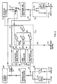
- FIG. 2 is a block diagram of a preferred embodiment of the instant invention.
- Those aspects of the dual deck VCR which are conventional in nature will not be described in detail. With reference to such figure, it includes two separate locations (decks) for magnetic storage media, e.g., video tapes in a cassette.
- One of these locations, represented by block 26, is for playing back a video signal, whereas the other location, represented by block 27, is for recording a video signal.
- Both of these locations include the conventional circuitry and mechanisms typically associated with the function for which it is intended and, in this connection, the blocks are referred to in the drawing respectively as a “playback scanner” and a “recording scanner” to indicate the common construction of playback and recording mechanisms.
- a dual deck VCR permits copying of a video signal on one magnetic storage medium onto another without the necessity of such signal having to pass through processing and modulation/demodulation circuitry.
- the video signal output from playback scanner 26 is fed to conventional demodulation and processing circuitry--including de-emphasizing circuitry--as is represented by block 28.
- the demodulated video signal is then fed to output means, generally referred to by the reference numeral 29.
- output means includes an amplifier 31 and a "video out" external connector represented at 32. It also includes an RF modulator 33 and an external connector for providing TV output 34. (Such RF modulation by modulator 33 enables the signal to be modulated for viewing on a selected channel or channels of a television set, typically channel 3 and/or 4.)
- the dual deck apparatus of the invention further includes an input means 36 to facilitate input of a video signal to be recorded from externally of the machine.
- Such input includes a "Video in” external connection 37 and an "Antenna in” external connection 38.
- An input switch represented at 39 is also provided to enable a user to select between video input and input from a TV antenna.
- An RF tuner represented at 41 is also provided as part of the input for enabling selection of the appropriate T.V. channel or the like to be recorded.
- the signal from the input means is directed through conventional processing circuitry, including circuitry for frequency modulation, pre-emphasis clipping, etc.
- circuitry may include automatic gain control circuitry of the type which will react to certain copy-protect signals on an externally applied video signal to be copied by interfering with the normal video signal levels. The result is that copies which are made will be unacceptable for viewing.
- the presence of such copy-protect signals will be detected, and a prohibit signal will be generated which will prevent the recording means from making a copy.
- the apparatus of the invention includes a switch, generally referred to by the reference numeral 43, which has two positions, one illustrated in full in which it is directly connected to the playback scanner and another illustrated in phantom in which it receives the video signal from the processing and frequency modulation circuitry 42 for recording.
- the position of the switch 43 is controlled externally of the apparatus by a select switch represented schematically at 44 as a "record mode" control.
- the switch control signal also is directed to logic to be described infra which reacts to the switch position.
- the dual deck apparatus of the invention simplifies the making of duplicate copies. That is, external cable hookups and the like are not necessary.
- the video signal which is output from the playback means 26 (the frequency modulated signal at the playback mechanism) is fed directly, after amplification represented by amplifier 45, to the internal recording pole 46 of switch 43 for application to the recording scanner. (The recording scanner will be prohibited from operating if the signal output from the playback scanner includes the copy-protect signal, as will be explained in more detail hereinafter.)
- Circuitry is included as part of the invention, to implement the logic flow chart of FIG. 1. Such circuitry is generally enclosed within the dotted line block 47. It includes a detector 48 for generating an output indicating whether or not the video signal outputted from the playback scanner includes the copy-protect signal, and a second detector represented at 49 for generating an output indicating if the copy-protect signal is present on the external video signal to be copied.
- the copy-protect circuitry 47 of the invention also includes two-input terminal AND gates 52-54, an invertor 56, and a three-input terminal OR gate 57.
- Detector 48 is connected, as illustrated schematically via line 58, to the output of the demodulation and processing circuitry 28 to enable detection by the same of the presence, or non-presence, of a copy-protect signal on any video signal emanating from the playback deck. Detector 48 will respond to the presence of a copy-protect signal on such output by delivering an activate signal to one of the input terminals of gate 52. When the record mode control is in the "internal" record mode, an activate signal also will be fed to the other input terminal of gate 52, with the result that the gate will generate an activate signal at its output which will be directed to one of the input terminals of OR gate 57, as is represented by flow line 59.
- OR gate 57 will respond thereto by generating a prohibit signal at its output which is directed, as is represented by flow line 61, to the recording means.
- the recording means reacts thereto by preventing the video signal which is fed directly to the recording deck from being recorded, as discussed above.
- the invention is also designed to prohibit recording in certain situations when an external video signal is applied to the recording means.
- One of these situations is when the program defined by a video signal being played is the same as the program defined by the video signal that is being fed to the circuitry for recording and the signal being played includes the copy-protect signal portion.
- the video signal which is generated by the playback scanner is directed to the video correlator 51 as represented by lines 58 and 62.
- the video signal it is desired to be recorded is also fed to the video correlator 51, as is represented by flow line 63.
- the video correlator compares the playback output signal to the record input video signal and, if they are the same, activates one input of AND gate 53, as is represented by flow line 64.
- AND gate 53 is connected to the output of detector 48 as illustrated, with the result that the output of the AND gate 53 will be activated whenever there is both a correlation between the two video signals and the playback output has the copy-protect signal.
- the output of AND gate 53 activates OR gate 57 to generate the prohibit recording signal discussed previously.
- video correlator enables one to playback a copy-protected program for viewing, while recording a different non-copy-protected program. It is only when the program being played back is the same as the program to be recorded and the program being played back is copy-protected, that the prohibit signal is generated.
- the invention also is designed to prevent recording of any video signal which includes the copy-protect signal portion, irrespective of the presence of processing circuitry and/or the effectiveness of the same to render any recording which is made acceptable for viewing. That is, the invention prevents recording without reliance on processing circuitry whenever external copying has been selected.
- all externally applied video signals to be recorded are directed to the detector 49, as is represented by the connection of the detector's input to flow line 63.
- Detector 49 reacts to the presence of a copy-protect signal on the video signal by applying an activate signal to one of the inputs of AND gate 54.
- the other input terminal of such AND gate is connected through invertor 56 to the record mode control flow line 66 so that when switch 43 is connected to receive an externally applied video signal, such input terminal will be activated.
- Line 66 represents, in effect, means for indicating whether the recording means is connected to the external input means or is connected to the output video signal of the playback scanner.
- the AND gate 54 will activate OR gate 57 to generate a record prohibit signal to be fed to the recording means.
- the preferred embodiment of the invention being described is particularly useful when the copy-protect signals are pulse pairs applied to portions of a video signal during the vertical blanking interval, in accordance with the teachings of U. S. Patent No. 4,631,603.
- These pulse pairs are, in essence, signal segments which provide voltage levels to the video signal at locations at which they are normally not required to produce a desired display, i.e., define the picture or operate the display mechanism.
- the invention is not limited to the copy-protect signal being of any particular type. From the broad standpoint, it could be any selected portion of a video signal which may be added for detection, irrespective of whether or not such video signal will interfere with the processing circuitry associated with recording.
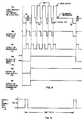
- the pulse pairs discussed previously are made up of alternate pseudo-sync pulses 67 and positive (or white) pulses 68 as illustrated in FIG. 4a.
- Figs. 3a-3c depict details of three alternate copy-protect signal detectors suitable for detectors 48 and 49 in such an instance.
- the video signal on line 63 or line 58 is fed to a sync tip restorer 71 which clamps the sync tips to a reference level, preferably 0 volts.
- the output of the sync tip restorer has essentially the same waveform as the original signal.
- FIG. 4 The output of restorer 71 is connected to a sync separator 72 which produces an output of sync pulses. These sync pulses are fed to a monostable multivibrator 73. The multivibrator is triggered by the trailing edges of the input sync pulses to generate nominally three microsecond sampling pulses. These pluses activate a sample and hold circuit 74 which also receives the output of sync tip restorer 71. Thus, sample and hold circuit 74 generates an output which represents the voltage level of the back porches of the modified video signal and holds it until the next sample.
- the envelope of the resultant output of sample and hold circuit 74 is shown more clearly in FIG. 5, which shows such envelope having a level of 0.3 volts during normal video horizontal lines and a level of 1 volt for those lines in the vertical blanking interval having the copy-protect signal.
- sample and hold circuit 74 is applied to the positive input of a positive voltage peak detector 76 which holds its most positive value for the duration of several fields. This assures that the output will have a value throughout the receipt of the modified video signal so that no part of the video signal can be recorded.
- the output of peak detector 76 is thus a constant voltage of about +0.3 volts in the case of a normal video signal and about +1.0 volt when the copy-protect signal corresponds to FIG. 4a.
- the output of detector 76 is joined to the positive input of the differential comparator 77.
- the negative input of comparator 77 is preferably connected to a positive 0.5 volt reference voltage.
- Comparator 77 thereby produces an output on lead 78 having an activate logic level, i.e., one which is high in the case of a modified or copy-protected video signal, and an inactivate (low) signal in the case of a normal video signal.
- circuitry to perform the functions identified by the blocks of FIG. 3a is well-known to persons of ordinary skill in the art and it does not form an aspect of the present invention other than in combination with the other circuits as described. They are therefore not discussed in detail.
- FIG. 3b an alternative embodiment of a detector is illustrated.
- the method of this embodiment relies on detecting the presence of the tightly grouped pseudo-sync pulses.
- the positive pulses are not utilized specifically, and therefore could be deleted.
- the wave form would look similar to the one in FIG. 4b, i.e., the one labelled "output of sync sep. 72".
- other forms of waveform could be used which also produce a frequency of normal sync pulses.
- the input video signal is fed to a sync separator 79 which produces an output similar to that of sync separator 72.
- the resulting series of pulses is input to a frequency-to-voltage converter 81.
- Convertor 81 generates an output voltage proportional to the frequency of its input pulses.
- the output of convertor 81 will thus have the general characteristics of the waveform of FIG. 5, in that it will be most positive during the vertical interval region corresponding to the increased sync frequency.
- the output of convertor 81 is coupled to a positive voltage peak detector 82 and differential comparator 83 which correspond to detector 76 and comparator 77, respectively, of the previously described embodiment.
- Detector 82 and comparator 83 are connected in the same arrangement as their corresponding elements in FIG. 3a, with the result the same logic level indication of the presence or absence of the modified or copy-protected video signal as was discussed with reference to the embodiment in FIG. 3a, is present on output line 84.
- FIG. 3c shows yet a third exemplary embodiment of a detector.
- Detector 86 functions similar to the detector of FIG. 3a in that it detects the presence of the white pulses by peak-detecting the video signal and sampling this peak-detected signal during the vertical blanking interval.
- the video signal is input to a sync tip restorer 87, the output of which is applied to a positive peak detector 88 having a fast charge time constant (less than 1 microsecond) and a long discharge time (about 100 microseconds).
- the output of sync tip restorer 87 is also connected to a sync separator 89 for generating an output waveform similar to that of sync separator 72 described with reference to FIG 3a.
- the output of separator 89 is coupled to a vertical sample pulse generator 91.
- Generator 91 produces a series of sampling pulses for activating a sample and hold circuit 92.
- Circuit 92 receives as input the output of peak detector 88.
- the output of the positive peak detector is sampled in sample and hold circuit 92 during the vertical interval at a time which coincides with the occurrence of the anti-copying waveform.
- circuit 92 will be at +0.3 volts in the case of a normal video signal and at about +1.0 volt in the case of a video signal modified or copy-protected as described.
- the output of sample and hold circuit 92 is converted to logic levels as described with reference to the embodiment of FIG. 3a by a differential comparator 93.
- FIG. 6 shows a preferred embodiment of video correlator 51 of FIG. 2.
- the two signals to be correlated i.e., the video signal to be recorded on line 63 and the video signal, if any, emanating from the playback deck on line 62, are applied to black level clamps 94 and 96.
- These circuits which are well-known in the art and need not be described in detail here, ensure that the video at their respective output terminals 97 and 98 has its blanking reference levels set to zero volts.
- Amplifier 99 in association with resistors 101 acts as a differential amplifier with a gain of unity. The signal at the output amplifier 99 is thus equal to the difference between the black-level-clamped input video signals.
- This signal is filtered by resistor 102 and capacitor 103, arranged to have a time constant of about one second.
- the voltage at 104 will be low - typically between -0.1 and +0.1 volts.
- the voltage at 104 will, from time-to-time during the programs, be outside these limits.
- Voltage 104 is sensed by a window discriminator comprising differential comparators 106 and 107, voltage references V1 and V2, and AND gate 108. The operation of a window discriminator is well understood in the art and will not be described further.
- the output at 108 will be at a high (activate) logic level indicating that the input video signals are very probably identical. If the voltage at 104 is outside these limits, then the output at 108 will be a low logic level indicating that the input video signals are not the same.
Landscapes
- Engineering & Computer Science (AREA)
- Signal Processing (AREA)
- Computer Security & Cryptography (AREA)
- Multimedia (AREA)
- General Engineering & Computer Science (AREA)
- Television Signal Processing For Recording (AREA)
- Signal Processing Not Specific To The Method Of Recording And Reproducing (AREA)
- Closed-Circuit Television Systems (AREA)
- Time Recorders, Dirve Recorders, Access Control (AREA)
- Management Or Editing Of Information On Record Carriers (AREA)
Claims (15)
- Vorrichtung mit mehr als einer Betriebsstelle für magnetische Speichermedien, mit einer Aufzeichnungseinrichtung (27) an einer ersten Betriebsstelle zum magnetischen Aufzeichnen eines Videosignals auf einem magnetischen Speichermedium an der ersten Stelle; einer Eingabeeinrichtung (36) zum Empfangen eines extern gelieferten Videosignals; einer Wiedergabeeinrichtung (26) an einer zweiten Betriebsstelle zum Ausgeben eines Videosignals von einem magnetischen Speichermedium an der zweiten Stelle; einer Steuereinrichtung (43, 44) zum selektiven Lenken des extern gelieferten Videosignals oder des von der Wiedergabeeinrichtung ausgegebenen Videosignals zu der Aufzeichnungseinrichtung (27) zum Aufzeichnen; und einer Nachweiseinrichtung (48, 49) zum Bestimmen, ob das extern gelieferte Videosignal oder das von der Wiedergabeeinrichtung (26) ausgegebene Videosignal ein Kopierschutzsignal hat und, in Antwort auf das Vorliegen eines Kopierschutzsignals auf einem der Videosignale, zum Erzeugen eines Verbotssignals, das die Aufzeichnungseinrichtung (27) am Aufzeichnen des Videosignals hindert, dadurch gekennzeichnet, daß die Nachweiseinrichtung (48, 49) einen ersten Detektor (48) zum Empfangen des von der Wiedergabeeinrichtung (26) ausgegebenen Videosignals und zum Bestimmen, ob das ausgegebene Videosignal ein Kopierschutzsignal hat, und einen zweiten Detektor (49) zum Empfangen des extern gelieferten Videosignals und zum Bestimmen, ob das gelieferte Videosignal ein Kopierschutzsignal hat, und eine Signalerzeugungseinrichtung (52 bis 57) aufweist, die auf die ersten und zweiten Detektoren (48, 49) und die Steuereinrichtung (43, 44) anspricht und dazu eingerichtet ist, ein Verbotssignal zu erzeugen, um ein Aufzeichnen durch die Aufzeichnungseinrichtung (27) zu verhindern, wenn bestimmt wird, daß das zu der Aufzeichnungseinrichtung gelenkte Videosignal ein Kopierschutzsignal hat.
- Vorrichtung nach Anspruch 1, wobei die Steuereinrichtung (43, 44) eine Schaltereinrichtung (43) zum alternativen Verbinden der Eingabeeinrichtung (36) für ein extern geliefertes Videosignal oder des von der Wiedergabeeinrichtung (26) ausgegebenen Videosignals mit der Aufzeichnungseinrichtung (27) aufweist.
- Vorrichtung nach Anspruch 2, die ferner eine Einrichtung zum Anzeigen, ob die Aufzeichnungseinrichtung (27) mit der externen Eingabeeinrichtung (36) oder mit dem von der Wiedergabeeinrichtung (26) ausgegebenen Videosignal verbunden ist, aufweist.
- Vorrichtung nach einem der vorhergehenden Ansprüche, die ferner eine Videokorrelatoreinrichtung (51) aufweist, die dazu eingerichtet ist, sowohl das von der Wiedergabeeinrichtung (26) ausgegebene Videosignal als auch das extern gelieferte Videosignal zu empfangen und die dazu eingerichtet ist zu bestimmen, ob die Videosignale im wesentlichen dieselben sind.
- Vorrichtung nach Anspruch 4, wobei die Signalerzeugungseinrichtung (52 bis 57) auch auf den Videokorrelator anspricht und dazu eingerichtet ist, ein Verbotssignal zu erzeugen, wenn beide Videosignale im wesentlichen dieselben sind und das von der Wiedergabeeinrichtung (26) ausgegebene Videosignal ein Kopierschutzsignal hat.
- Vorrichtung nach Anspruch 4 oder 5, wobei die Videokorrelatoreinrichtung (51) eine Einrichtung (94, 96) zum Legen von Teilen der Videosignale auf denselben Spannungspegel aufweist.
- Vorrichtung nach einem der Ansprüche 4 bis 6, wobei die Videokorrelatoreinrichtung (51) eine Einrichtung (99) zum Bestimmen, ob Differenzen zwischen den Spannungen der beiden Videosignale außerhalb eines vorgegebenen Bereiches liegen, aufweist.
- Vorrichtung nach einem der vorhergehenden Ansprüche, wobei das Kopierschutzsignal ein Signalsegment aufweist, das einen Spannungspegel an einer Stelle hat, an der er normalerweise von einem Videosignal nicht benötigt wird, um eine gewünschte Anzeige zu erzeugen, und wobei jeder der ersten und zweiten Detektoren (48, 49) das Vorliegen dieses Spannungspegels an dieser Stelle nachweist.
- Vorrichtung nach Anspruch 8, wobei die Stelle mit dem vorgewählten Signalsegment während des Vertikalaustastintervalls eines Videosignals auftritt.
- Vorrichtung nach Anspruch 8 oder 9, wobei die Nachweiseinrichtung (48, 49) einen Spannungsspitzendetektor zum Nachweisen des Vorliegens dieses Spannungspegels an dieser Stelle aufweist.
- Verfahren zum Verhindern, daß ein Videosignal mit einem Kopierschutzsignal von einem magnetischen Medium zu einem anderen kopiert wird, in einer Vorrichtung mit mehr als einer Betriebsstelle für magnetische Medien, wobei die Vorrichtung eine Aufzeichnungseinrichtung (27) an einer ersten Stelle zum magnetischen Aufzeichnen eines Videosignals auf einem magnetischen Speichermedium an der ersten Stelle; eine Eingabeeinrichtung (36) zum Empfangen eines extern gelieferten Videosignals; eine Wiedergabeeinrichtung (26) an einer zweiten Stelle zum Ausgeben eines Videosignals von einem magnetischen Speichermedium an der zweiten Stelle; und eine Steuereinrichtung (43, 44) zum selektiven Lenken des extern gelieferten Videosignals oder des von der Wiedergabeeinrichtung ausgegebenen Videosignals zu der Aufzeichnungseinrichtung zum Aufzeichnen aufweist; und wobei das Verfahren die Schritte aufweist, zu bestimmen, ob das von der Wiedergabeeinrichtung (26) ausgegebene Videosignal oder das extern gelieferte Videosignal ein Kopierschutzsignal hat, und, in Antwort auf das Vorliegen eines Kopierschutzsignals auf einem der Videosignale, ein Verbotssignal zu erzeugen, das die Aufzeichnungseinrichtung (27) am Aufzeichnen dieses Videosignals hindert, dadurch gekennzeichnet, daß das Verfahren ferner die Schritte aufweist, das von der Wiedergabeeinrichtung (26) ausgegebene Videosignal an einen ersten Detektor (48) anzulegen, der eingerichtet ist zu bestimmen, ob das von der Wiedergabeeinrichtung ausgegebene Videosignal ein Kopierschutzsignal hat, das extern gelieferte Videosignal an einen zweiten Detektor (49) anzulegen, der eingerichtet ist zu bestimmen, ob das extern gelieferte Videosignal ein Kopierschutzsignal hat, und das Verbotssignal zu erzeugen, um ein Aufzeichnen durch die Aufzeichnungseinrichtung (27) zu verhindern, wenn bestimmt wird, daß das von der Steuereinrichtung (43, 44) zu der Aufzeichnungseinrichtung gelenkte Videosignal ein Kopierschutzsignal hat.
- Verfahren nach Anspruch 11, das ferner den Schritt aufweist zu bestimmen, ob das von der Wiedergabeeinrichtung (26) ausgegebene Videosignal im wesentlichen dasselbe ist wie das extern gelieferte Videosignal.
- Verfahren nach Anspruch 12, das ferner den Schritt aufweist, ein Verbotssignal zu erzeugen, wenn beide Videosignale im wesentlichen dieselben sind und das von der Wiedergabeeinrichtung ausgegebene Videosignal ein Kopierschutzsignal hat.
- Verfahren nach einem der Ansprüche 11 bis 13, wobei das Kopierschutzsignal ein Signalsegment aufweist, das einen Spannungspegel an einer Stelle hat, an der er normalerweise von dem Videosignal nicht benötigt wird, um eine gewünschte Anzeige zu erzeugen, und wobei jeder der ersten und zweiten Detektoren (48, 49) das Vorliegen eines Kopierschutzsignals durch Nachweisen des Vorliegens dieses Spannungspegels an dieser Stelle bestimmt.
- Verfahren nach Anspruch 14, wobei die Stelle mit dem Signalsegment während des Vertikalaustastintervalls des Videosignals auftritt.
Applications Claiming Priority (2)
| Application Number | Priority Date | Filing Date | Title |
|---|---|---|---|
| US07/210,665 US4937679A (en) | 1986-08-11 | 1988-06-23 | Dual deck video recording apparatus having enhanced copy protection and method for providing enhanced copy protection to such a recording apparatus |
| US210665 | 1988-06-23 |
Publications (3)
| Publication Number | Publication Date |
|---|---|
| EP0348218A2 EP0348218A2 (de) | 1989-12-27 |
| EP0348218A3 EP0348218A3 (de) | 1992-01-15 |
| EP0348218B1 true EP0348218B1 (de) | 1995-05-17 |
Family
ID=22783779
Family Applications (1)
| Application Number | Title | Priority Date | Filing Date |
|---|---|---|---|
| EP89306379A Expired - Lifetime EP0348218B1 (de) | 1988-06-23 | 1989-06-23 | Doppeldeck-Videoaufzeichnungseinrichtung und Verfahren |
Country Status (8)
| Country | Link |
|---|---|
| US (1) | US4937679A (de) |
| EP (1) | EP0348218B1 (de) |
| JP (1) | JP3190654B2 (de) |
| KR (1) | KR940006160B1 (de) |
| AT (1) | ATE122835T1 (de) |
| DE (1) | DE68922658T2 (de) |
| ES (1) | ES2072300T3 (de) |
| PH (1) | PH26068A (de) |
Families Citing this family (35)
| Publication number | Priority date | Publication date | Assignee | Title |
|---|---|---|---|---|
| USRE40689E1 (en) | 1983-11-23 | 2009-03-31 | Macrovision Corporation | Method and apparatus for disabling anti-copy protection system in video signals |
| EP0297539B1 (de) * | 1987-06-30 | 1993-09-01 | Kabushiki Kaisha Toshiba | Aufzeichnungssteuergerät |
| US5231546A (en) * | 1988-02-10 | 1993-07-27 | Matsushita Electric Industrial Co., Ltd. | Recording and reproducing apparatus with limited digital copying |
| US5057947A (en) * | 1988-02-10 | 1991-10-15 | Matsushita Electric Industrial Co., Ltd. | Recording and reproducing apparatus with limited digital copying |
| JPH02309778A (ja) * | 1989-05-24 | 1990-12-25 | Victor Co Of Japan Ltd | クロック生成回路 |
| GB2234848A (en) * | 1989-08-09 | 1991-02-13 | Andrew Ziolek | Video apparatus |
| KR930006520B1 (ko) * | 1991-04-19 | 1993-07-16 | 삼성전자 주식회사 | 복사방지 시스템 |
| US5177618A (en) * | 1990-06-29 | 1993-01-05 | Go-Video, Inc. | Dual deck vcr and duplicating circuit therefor |
| JP3210680B2 (ja) * | 1990-12-18 | 2001-09-17 | パイオニア株式会社 | 情報再生装置 |
| JPH0549001A (ja) * | 1991-08-21 | 1993-02-26 | Sony Corp | ビデオ信号記録装置 |
| JP3134894B2 (ja) * | 1992-01-16 | 2001-02-13 | ソニー株式会社 | 複製防止処理の有無検出装置 |
| JP3128328B2 (ja) * | 1992-05-26 | 2001-01-29 | キヤノン株式会社 | 記録装置 |
| JP3217137B2 (ja) * | 1992-07-28 | 2001-10-09 | 株式会社日立製作所 | 映像信号記録装置、再生装置及び伝送装置 |
| US5315448A (en) * | 1993-03-18 | 1994-05-24 | Macrovision Corporation | Copy protection for hybrid digital video tape recording and unprotected source material |
| JP2945569B2 (ja) * | 1993-10-27 | 1999-09-06 | シャープ株式会社 | 情報記録再生方法 |
| JPH07307900A (ja) * | 1994-05-12 | 1995-11-21 | Funai Electric Co Ltd | ビデオ一体型テレビにおける外部入力信号処理回路 |
| KR0152788B1 (ko) | 1994-11-26 | 1998-10-15 | 이헌조 | 디지탈 영상 시스템의 복사 방지 방법 및 장치 |
| KR0136458B1 (ko) | 1994-12-08 | 1998-05-15 | 구자홍 | 디지탈 자기 기록재생 시스템의 복사 방지장치 |
| MY125739A (en) * | 1994-12-22 | 2006-08-30 | Sony Corp | Recording medium and apparatus for protecting copyrighted digital data |
| US5737417A (en) * | 1995-04-24 | 1998-04-07 | Technicolor Videocassette, Inc. | Videotape anti-copying encryption scheme |
| KR960038875A (ko) * | 1995-04-27 | 1996-11-21 | 김광호 | 복합영상기록재생기의 신호입출력라인 스위칭회로 |
| DE19525425C1 (de) * | 1995-07-12 | 1996-10-24 | Siemens Ag | Videosignalempfangseinrichtung mit Aufzeichnungsschutz |
| US6122377A (en) * | 1995-07-12 | 2000-09-19 | Siemens Aktiengesellschaft | Video signal receiver with record protection |
| JP4355819B2 (ja) * | 1995-10-17 | 2009-11-04 | マクロヴィジョン コーポレイション | 複製保護信号の影響を除去または低減、もしくはパルス位置決定する方法または装置 |
| US6684199B1 (en) | 1998-05-20 | 2004-01-27 | Recording Industry Association Of America | Method for minimizing pirating and/or unauthorized copying and/or unauthorized access of/to data on/from data media including compact discs and digital versatile discs, and system and data media for same |
| AU4407199A (en) | 1998-05-20 | 1999-12-06 | Recording Industry Association Of America | Copy protection method using broken modulation rules |
| FR2783658B1 (fr) | 1998-09-23 | 2000-10-13 | Thomson Multimedia Sa | Protection contre la copie de donnees numeriques stockees sur un support d'informations |
| TW566041B (en) * | 2001-07-06 | 2003-12-11 | Hitachi Ltd | Digital data recording device and output device |
| US20060093139A1 (en) * | 2004-10-28 | 2006-05-04 | Macrovision Corporation | Defeat method and apparatus for content management for high definition television |
| US7792293B2 (en) * | 2005-05-06 | 2010-09-07 | Rovi Solutions Corporation | Method and apparatus for modifying a subsequently generated control command in a content control system |
| CN101611323B (zh) * | 2006-09-29 | 2013-02-20 | 密理博公司 | 流式细胞术脉冲的区分和应用 |
| US8428258B2 (en) * | 2007-05-02 | 2013-04-23 | Rovi Technologies Corporation | Method and apparatus for providing content control via detection of modifications to a signal |
| US20110081129A1 (en) | 2009-10-07 | 2011-04-07 | Rovi Technologies Corporation | Broadband recording method and apparatus for video and/or audio programs |
| US8306403B2 (en) | 2010-03-29 | 2012-11-06 | Rovi Technologies Corporation | Content control via guide data and/or metadata |
| US9049073B2 (en) | 2011-06-28 | 2015-06-02 | Rovi Guides, Inc. | Systems and methods for initializing allocations of transport streams based on historical data |
Family Cites Families (4)
| Publication number | Priority date | Publication date | Assignee | Title |
|---|---|---|---|---|
| US3947884A (en) * | 1972-10-04 | 1976-03-30 | Clarion Co., Ltd. | Tape recorder |
| JPS52114313A (en) * | 1976-03-23 | 1977-09-26 | Sony Corp | Recorded medium and production method therefor |
| US4631603A (en) * | 1985-04-17 | 1986-12-23 | Macrovision | Method and apparatus for processing a video signal so as to prohibit the making of acceptable video tape recordings thereof |
| KR930008167B1 (ko) * | 1986-08-11 | 1993-08-26 | 매크로비젼 코포레이션 | 비데오 레코더의 비데오 디스에이블링 회로를 이용하여 비데오 프로그램의 복사를 방지하는 방법 및 장치 |
-
1988
- 1988-06-23 US US07/210,665 patent/US4937679A/en not_active Expired - Lifetime
-
1989
- 1989-06-23 EP EP89306379A patent/EP0348218B1/de not_active Expired - Lifetime
- 1989-06-23 KR KR1019890008698A patent/KR940006160B1/ko not_active Expired - Lifetime
- 1989-06-23 ES ES89306379T patent/ES2072300T3/es not_active Expired - Lifetime
- 1989-06-23 PH PH38840A patent/PH26068A/en unknown
- 1989-06-23 JP JP15978589A patent/JP3190654B2/ja not_active Expired - Lifetime
- 1989-06-23 AT AT89306379T patent/ATE122835T1/de not_active IP Right Cessation
- 1989-06-23 DE DE68922658T patent/DE68922658T2/de not_active Expired - Lifetime
Also Published As
| Publication number | Publication date |
|---|---|
| US4937679A (en) | 1990-06-26 |
| KR940006160B1 (ko) | 1994-07-08 |
| PH26068A (en) | 1992-01-29 |
| EP0348218A3 (de) | 1992-01-15 |
| HK1002419A1 (en) | 1998-08-21 |
| JPH0264947A (ja) | 1990-03-05 |
| ES2072300T3 (es) | 1995-07-16 |
| KR900000853A (ko) | 1990-01-31 |
| JP3190654B2 (ja) | 2001-07-23 |
| DE68922658D1 (de) | 1995-06-22 |
| DE68922658T2 (de) | 1995-10-19 |
| ATE122835T1 (de) | 1995-06-15 |
| EP0348218A2 (de) | 1989-12-27 |
Similar Documents
| Publication | Publication Date | Title |
|---|---|---|
| EP0348218B1 (de) | Doppeldeck-Videoaufzeichnungseinrichtung und Verfahren | |
| US4907093A (en) | Method and apparatus for preventing the copying of a video program | |
| EP0559763B1 (de) | Verfahren und gerät zum ausschalten eines anti-kopier-schutzsystems in videosignalen | |
| US5315448A (en) | Copy protection for hybrid digital video tape recording and unprotected source material | |
| US5157510A (en) | Method and apparatus for disabling anti-copy protection system in video signals using pulse narrowing | |
| KR100328211B1 (ko) | 화상정보전송방식,화상정보기록장치및화상정보재생장치 | |
| EP0256753B1 (de) | Verfahren und Gerät zur Verhinderung des Kopierens eines Video-Programms | |
| AU577011B2 (en) | Video signal processor for prohibiting vtr recording | |
| HK1008109B (en) | Method and apparatus for preventing the copying of a video program | |
| US6600873B1 (en) | Method and apparatus for detecting modified color burst signals to prevent the copying of a video program | |
| JP2690933B2 (ja) | 信号判別装置 | |
| US5589946A (en) | Video signal reproduction apparatus replacing drop-cut signal portions | |
| HK1002419B (en) | Dual deck video recording apparatus and method | |
| USRE40689E1 (en) | Method and apparatus for disabling anti-copy protection system in video signals | |
| JPH03167979A (ja) | 磁気記録再生装置 | |
| CA2283849C (en) | Method and apparatus for detecting modified color burst signals to prevent the copying of a video program | |
| JPH0292079A (ja) | 映像信号のダビング装置 | |
| KR19980052601A (ko) | 브이씨알의 복사 방지 비디오 테이프 검출 장치 | |
| JPH04144385A (ja) | Vtr | |
| JPH11331758A (ja) | ビデオ記録再生機器用自動利得制御装置 |
Legal Events
| Date | Code | Title | Description |
|---|---|---|---|
| PUAI | Public reference made under article 153(3) epc to a published international application that has entered the european phase |
Free format text: ORIGINAL CODE: 0009012 |
|
| AK | Designated contracting states |
Kind code of ref document: A2 Designated state(s): AT BE CH DE ES FR GB GR IT LI LU NL SE |
|
| PUAL | Search report despatched |
Free format text: ORIGINAL CODE: 0009013 |
|
| AK | Designated contracting states |
Kind code of ref document: A3 Designated state(s): AT BE CH DE ES FR GB GR IT LI LU NL SE |
|
| 17P | Request for examination filed |
Effective date: 19920323 |
|
| 17Q | First examination report despatched |
Effective date: 19930809 |
|
| GRAA | (expected) grant |
Free format text: ORIGINAL CODE: 0009210 |
|
| AK | Designated contracting states |
Kind code of ref document: B1 Designated state(s): AT BE CH DE ES FR GB GR IT LI LU NL SE |
|
| PG25 | Lapsed in a contracting state [announced via postgrant information from national office to epo] |
Ref country code: IT Free format text: LAPSE BECAUSE OF FAILURE TO SUBMIT A TRANSLATION OF THE DESCRIPTION OR TO PAY THE FEE WITHIN THE PRE;WARNING: LAPSES OF ITALIAN PATENTS WITH EFFECTIVE DATE BEFORE 2007 MAY HAVE OCCURRED AT ANY TIME BEFORE 2007. THE CORRECT EFFECTIVE DATE MAY BE DIFFERENT FROM THE ONE RECORDED.SCRIBED TIME-LIMIT Effective date: 19950517 Ref country code: CH Effective date: 19950517 Ref country code: GR Free format text: LAPSE BECAUSE OF FAILURE TO SUBMIT A TRANSLATION OF THE DESCRIPTION OR TO PAY THE FEE WITHIN THE PRESCRIBED TIME-LIMIT Effective date: 19950517 Ref country code: LI Effective date: 19950517 |
|
| REF | Corresponds to: |
Ref document number: 122835 Country of ref document: AT Date of ref document: 19950615 Kind code of ref document: T |
|
| REF | Corresponds to: |
Ref document number: 68922658 Country of ref document: DE Date of ref document: 19950622 |
|
| ET | Fr: translation filed | ||
| PG25 | Lapsed in a contracting state [announced via postgrant information from national office to epo] |
Ref country code: LU Free format text: LAPSE BECAUSE OF NON-PAYMENT OF DUE FEES Effective date: 19950630 |
|
| REG | Reference to a national code |
Ref country code: ES Ref legal event code: FG2A Ref document number: 2072300 Country of ref document: ES Kind code of ref document: T3 |
|
| PG25 | Lapsed in a contracting state [announced via postgrant information from national office to epo] |
Ref country code: SE Effective date: 19950817 |
|
| REG | Reference to a national code |
Ref country code: CH Ref legal event code: PL |
|
| BECA | Be: change of holder's address |
Free format text: 950517 *MACROVISION CORP.:700 EL CAMINO REAL - EAST SUITE 200, MOUNTAIN VIEW CA 94040 |
|
| PLBE | No opposition filed within time limit |
Free format text: ORIGINAL CODE: 0009261 |
|
| STAA | Information on the status of an ep patent application or granted ep patent |
Free format text: STATUS: NO OPPOSITION FILED WITHIN TIME LIMIT |
|
| 26N | No opposition filed | ||
| REG | Reference to a national code |
Ref country code: GB Ref legal event code: IF02 |
|
| REG | Reference to a national code |
Ref country code: FR Ref legal event code: CA |
|
| PGFP | Annual fee paid to national office [announced via postgrant information from national office to epo] |
Ref country code: AT Payment date: 20080612 Year of fee payment: 20 |
|
| REG | Reference to a national code |
Ref country code: GB Ref legal event code: 732E |
|
| PGFP | Annual fee paid to national office [announced via postgrant information from national office to epo] |
Ref country code: NL Payment date: 20080603 Year of fee payment: 20 Ref country code: DE Payment date: 20080626 Year of fee payment: 20 Ref country code: ES Payment date: 20080717 Year of fee payment: 20 |
|
| PGFP | Annual fee paid to national office [announced via postgrant information from national office to epo] |
Ref country code: FR Payment date: 20080617 Year of fee payment: 20 |
|
| PGFP | Annual fee paid to national office [announced via postgrant information from national office to epo] |
Ref country code: GB Payment date: 20080625 Year of fee payment: 20 |
|
| PGFP | Annual fee paid to national office [announced via postgrant information from national office to epo] |
Ref country code: BE Payment date: 20080814 Year of fee payment: 20 |
|
| REG | Reference to a national code |
Ref country code: FR Ref legal event code: GC |
|
| BE20 | Be: patent expired |
Owner name: *MACROVISION CORP. Effective date: 20090623 |
|
| REG | Reference to a national code |
Ref country code: GB Ref legal event code: PE20 Expiry date: 20090622 |
|
| PG25 | Lapsed in a contracting state [announced via postgrant information from national office to epo] |
Ref country code: NL Free format text: LAPSE BECAUSE OF EXPIRATION OF PROTECTION Effective date: 20090623 |
|
| REG | Reference to a national code |
Ref country code: ES Ref legal event code: FD2A Effective date: 20090624 |
|
| NLV7 | Nl: ceased due to reaching the maximum lifetime of a patent |
Effective date: 20090623 |
|
| PG25 | Lapsed in a contracting state [announced via postgrant information from national office to epo] |
Ref country code: ES Free format text: LAPSE BECAUSE OF EXPIRATION OF PROTECTION Effective date: 20090624 |
|
| PG25 | Lapsed in a contracting state [announced via postgrant information from national office to epo] |
Ref country code: GB Free format text: LAPSE BECAUSE OF EXPIRATION OF PROTECTION Effective date: 20090622 |
|
| REG | Reference to a national code |
Ref country code: FR Ref legal event code: RG Ref country code: FR Ref legal event code: CD |