EP0348176A2 - Thermodruckverfahren - Google Patents
Thermodruckverfahren Download PDFInfo
- Publication number
- EP0348176A2 EP0348176A2 EP89306266A EP89306266A EP0348176A2 EP 0348176 A2 EP0348176 A2 EP 0348176A2 EP 89306266 A EP89306266 A EP 89306266A EP 89306266 A EP89306266 A EP 89306266A EP 0348176 A2 EP0348176 A2 EP 0348176A2
- Authority
- EP
- European Patent Office
- Prior art keywords
- pair
- platen
- pinch rollers
- upper frame
- lever
- Prior art date
- Legal status (The legal status is an assumption and is not a legal conclusion. Google has not performed a legal analysis and makes no representation as to the accuracy of the status listed.)
- Granted
Links
Images


Classifications
-
- B—PERFORMING OPERATIONS; TRANSPORTING
- B41—PRINTING; LINING MACHINES; TYPEWRITERS; STAMPS
- B41J—TYPEWRITERS; SELECTIVE PRINTING MECHANISMS, i.e. MECHANISMS PRINTING OTHERWISE THAN FROM A FORME; CORRECTION OF TYPOGRAPHICAL ERRORS
- B41J25/00—Actions or mechanisms not otherwise provided for
- B41J25/304—Bodily-movable mechanisms for print heads or carriages movable towards or from paper surface
- B41J25/316—Bodily-movable mechanisms for print heads or carriages movable towards or from paper surface with tilting motion mechanisms relative to paper surface
Definitions
- the present invention relates to a thermal printing system, and more particularly, to a thermal printing system which prints alphanumerical and or graphic information, on a paper sheet cut into unified sheet size of A4,B5 or the likefed from a casette case, by melting a film of printing ink applied on a plastics membrane by the heat imparted by a thermal head,which further comprises at least a means for for selectively depressing or releasing a pair of pinch rollers against a platen,thereby allowing the user who operates the system to readily remove any paper crumpled between the platen and the pinch rollers.
- thermal printing systems which prints a number of dots of printing ink corresponding to alphanumerical and or graphic information printed by a thermal head of the printing system on a paper sheet,cut into unidfied size,by thermally melting a film of printing ink applied on the surface of a plastic membrane in a dried state at an ambient temperature.
- paper sheets for printing are supplied as a set of cut paper sheets each cut into such a unified size of A4,B5 or the like and are contained in a casette case each capable of receiving a number of paper sheets,,say,50 or 100,and these paper sheets are automatically fed or propelled as printing proceeds on.
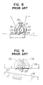
- This publication discloses a thermal printing system which comprises as shown in Fig. 8; a platen 21,a pair of pinch rollers 23 each pinch roller of which is disposed to be freely rotatable to each of a pair of pinch levers 22 and capable of being depressed against or released from said platen 21,and aforesaid depressing and releasing action of this printing system is effected by such manner that the depression of the pinch rollers 23 against the platen 21 is done by a pinch roller lever tensioning spring 24 connected between both the swingable ends of the pinch roller lever 22 and the releasing of the deppressed pinch rollers is effected by a manual releasing lever 25 rotatable about a pin as an axis of rotation.
- This manual releasing lever 25 is provided,at said one end,with a rotary disc 26 which normally does not impart any force to the pinch roller levers 22,but it acts to make the pinch rollers 23 to move away from the platen 21,only when the manual releasing lever 25 is turned at a specified angle in a direction opposite to that for depressing the pinch rollers,namely,the pinch roller lever at the left side is turned clockwise and the pinch roller lever at the right side is turned opposite,that is,anticlockwise
- thermo printing system provided with a depression/ release lever 25′fixedly attached with a a return lever 29 for returning aforesaid releasing lever 25′, in which the return lever 29 acts to return the depression/release lever 25′ when the return lever 29 contacts the lower frame 28 when the upper frame 27 is lowered onto the lower frame frame 28 for closing.
- the present invention has been conceived and developed to solve the above-mentioned problems, and it aims to provide a thermal printing system which can prevent such a misuse and also to make it possible that a paper sheet in a crumpled state can be readily removed by such a mere simple action of opening the upper frame upward,by providing a mechanism which enables depression of the pinch rollers on the platen or releasing the depressed pinch rollers on the platen can be automatically set in connection with the open ing or closing of the upper frame with respect to the lower frame of the system.
- an object of the present invention is to provide a thermal printing system for printing alphanumerical and or graphic information on a cut paper sheet by melting the film of thermal printing ink applied on a plastic film by means of heat imparted by a thermal head,which system is attached with a device for automatically setting a platen and a pair of pinch rollers in a state capable of removing a paper sheet being crumpled between the platen and the pinch rollers.
- Another object of the present invention is to provide a thermal printing system which has a mechanism enabling the user to manually remove crumpled sheet of paper by means of forming a gap between a platen and a pair pinch rollers, by a mere upward opening of the upper frame from the lower frame of the system.
- a further object of the present invention is to provide a thermal printing system having a more simplified mechanism but enables ready removal of the crumpled paper sheet in more ready manner,merely by disposing a pinch roller depresing assembly including a platen and a pair of pinch rollers together with a depression /release lever,on the lower frame and by swingably raising the upper frame.
- Two measures were taken in the present invention to set the pinch rollers s ther in depressed state or in released state by user's opening or closing action.
- a first measure is to provide a depression/release lever which acts in respose to the user's opening or closing action.
- the front end of the depression/release lever will engage a part of the lower frame,when the upper frame is lowered down onto the lower frame as a "closed" state,then the lever is allowed to rotate accompanying rotation of a coaxially fixed cam means to move away from the pinch roller levers,thereby the pinch rollers are depressed under resilient force against the surface of the platen ready for normal printing.
- Components such as pinch rollers, a platen and means for depressing and releasing the pinch rollers are disposed at the lower frame side wherein a depression/release lever as said depressing and releasing means is made swingable and one lengthwise end is rendered possible to engage the lower face of the upper frame,while the other free end is provided with protrusions which act as a wedge or cam means and act to engage the inside face of each support pin of the pinch roller levers.
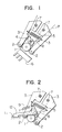
- Figs.1 and 2 are schematic side views illustrating the cam and the depression/release lever and their relating parts of a thermal printing system of the present invention when the upper frame is closed with respect to the lower frame,and showing the pinch rollers being depressed,namely, urged toward the the platen,while Fig.3 depicts the cam and the depression/release lever and their relating parts,where the upper frame is opened with respect to the lower frame.
- Fig.4 is a side view illustrating the entire thermal printing system of a first embodiment of the present invention where the upper frame is raised upward to open the printing system.
- numbereral 10 is an upper frame and 11 is a lower frame,and the former is attached to the latter being able to be selectively opened or closed with each other,so that the upper frame can be secured tightly to the lower frame by a locking means (not shown)
- Numeral 1 is a platen and 2 is a pair of pinch rollers opposedly facing with each other and 3 denotes a pair of pinch roller levers,and these members,together with their related parts,are attached to the platen 1.
- Each of the pinch roller levers 3 is swingably received at its one end by a pinch roller lever supporting pin 7, while the other end is attached with a freely rotatable pinch roller 2,which together with the other one constitute a pair to be resiliently biased by a tension spring 5 extended between the two pieces of the pinch roller levers 3,so that the pinch rollers in a pair can be depressed on the surface of the platen 1 from its opposite side as if the rollers 2 can embrace or hold the platen 1 from the oppsite sides.
- numbereral 4 is a cam and 12 denotes a crank-arm type depression/release lever for urging the pinch roller lever 3.
- the cam 4 is disposed between the opposedly facing pinch roller levers 3 in a pair,so that it normally does not exert any force to the pinch roller lever 3,but it acts to urge the pinch roller levers 3 to move away from each other against the tensional force imparted by the tension spring 5 when the cam is turned by a specified angle,while the lever 12 is disposed such that its front end engages with or leaves away from the lower frame 11 depend on the user's closing or opening of the upper frame.
- the cam 4 and the lever 12 are fixedly attached to a rotatable connecting pin 8,so the cam 4 and lever 12 can integrally rotate as a single member,in addition,the lever 12 is biased by a tension force given by a tension spring 9 to be normally turned in anticlockkwise direction.
- the pinch rollers 2 can be selectively depressed upon or released from the surface of the platen 1 in an interrelated manner.
- upper frame 10 is lowered down onto the lower frame 11 and then a paper sheet is fed from the casette case,then a desired image of information can be printed at the contact point with the platen 1 by means of thermal printing effected by the thermal head 6.
- the platen, pinch rollers and related parts or components are mounted on the upper frame 10 as shown in Figs.2 and 3,however,these members in the second embodiments are attached to the lower frame 11 as shown in Figs.5,6 and 7.
- Fig.5 is a side view showing,a depression/release lever 14 and its related parts or components,when the upper frame 10 is closed onto the lower frame,
- Fig.6 shows that they are in opened state
- Fig.7 is a side view showing the entire profile of the thermal printing system of the present invention, and it shows that the upper frame 10 can be opened or closed with respect to the lower frame 11.
- the upper frame 10 shown by solid line is the state where the upper frame is opened by raising the upper frame, while that shown by dash and dot line is the upper frame 10 being closed.
- numeral 1 is a platen
- 2 and 3 are pair of pinch rollers and pinch roller levers,respectively.
- pinch rollers and pinch roller levers in each pair are oppositely facing with each other and these members including the platen are disposed on the lower frame 11.
- Each of the pinch roller lever 3 is rotatably disposed at its one end around a pinch roller lever supporting pin 7 and is attached with a pinch roller 2 at its the other end, and both pinch rollers oppositely facing with each other are resiliently biased by a pinch roller lever tensioning spring 5 so that both pinch rollers can be depressed on the surface of the platen 1 from its opposite side.
- Numeral 14 is a depression/release lever swingably received at its intermediate portion by a supporting pin 8 disposed on the lower frame 11,while one end of the lever 14 is engageable with the lower face of the upper frame 10 and its the other end is formed with two protrusions 4a and 4b alike two cams or wedges,each of which is made engageable with the inside face of a pair of pins 2a for supporting each of the pair of pinch rollers 2,respectively.
- thermal printing system according to the second embodiment is constructed as explained above,depresssing and releasing of the pinch rollers 2 to the platen 1 can be automatically effected either by closing or by opening the upper frame 10 to the lower frame 11.
Landscapes
- Handling Of Cut Paper (AREA)
- Handling Of Sheets (AREA)
Applications Claiming Priority (4)
| Application Number | Priority Date | Filing Date | Title |
|---|---|---|---|
| JP8112388U JPH029552U (de) | 1988-06-21 | 1988-06-21 | |
| JP81123/88U | 1988-06-21 | ||
| JP10652488U JPH0642854Y2 (ja) | 1988-08-13 | 1988-08-13 | 熱転写記録装置 |
| JP106524/88U | 1988-08-13 |
Publications (3)
| Publication Number | Publication Date |
|---|---|
| EP0348176A2 true EP0348176A2 (de) | 1989-12-27 |
| EP0348176A3 EP0348176A3 (en) | 1990-10-31 |
| EP0348176B1 EP0348176B1 (de) | 1994-04-27 |
Family
ID=26422167
Family Applications (1)
| Application Number | Title | Priority Date | Filing Date |
|---|---|---|---|
| EP89306266A Expired - Lifetime EP0348176B1 (de) | 1988-06-21 | 1989-06-21 | Thermodruckverfahren |
Country Status (4)
| Country | Link |
|---|---|
| US (1) | US4947185A (de) |
| EP (1) | EP0348176B1 (de) |
| CA (1) | CA1324027C (de) |
| DE (1) | DE68914889T2 (de) |
Cited By (2)
| Publication number | Priority date | Publication date | Assignee | Title |
|---|---|---|---|---|
| EP0765761A1 (de) * | 1995-09-29 | 1997-04-02 | Anritsu Corporation | Wärmedruckgerät |
| FR2755641A1 (fr) * | 1996-11-12 | 1998-05-15 | Axiohm | Dispositif d'impression d'un support en bande |
Families Citing this family (8)
| Publication number | Priority date | Publication date | Assignee | Title |
|---|---|---|---|---|
| US5516219A (en) * | 1994-08-01 | 1996-05-14 | Lasermaster Corporation | High resolution combination donor/direct thermal printer |
| US5759150A (en) * | 1995-07-07 | 1998-06-02 | Olympus Optical Co., Ltd. | System for evulsing subcutaneous tissue |
| US6261009B1 (en) | 1996-11-27 | 2001-07-17 | Zih Corporation | Thermal printer |
| US5806993A (en) * | 1997-03-18 | 1998-09-15 | Comtec Information Systems, Inc. | Portable interactive miniature printer |
| US6010257A (en) * | 1997-03-18 | 2000-01-04 | Comtec Information Systems Inc. | Miniature portable interactive printer |
| US6079891A (en) * | 1997-11-04 | 2000-06-27 | Axiohm | Printer device for printing a strip medium |
| US6166886A (en) * | 1998-03-20 | 2000-12-26 | Seagate Technology Llc | Swageless head suspension and method of assembly therefor |
| TWI279322B (en) * | 2004-06-23 | 2007-04-21 | Seiko Epson Corp | Printing unit |
Citations (5)
| Publication number | Priority date | Publication date | Assignee | Title |
|---|---|---|---|---|
| US2142245A (en) * | 1936-03-09 | 1939-01-03 | Underwood Elliott Fisher Co | Typewriting machine |
| US4042091A (en) * | 1976-03-25 | 1977-08-16 | Xerox Corporation | Record material feed apparatus |
| DE3319490A1 (de) * | 1982-06-17 | 1983-10-13 | Alps Electric Co., Ltd., Tokyo | Papierandrueckmechanismus fuer aufzeichnungsgeraete |
| JPS6292873A (ja) * | 1985-10-18 | 1987-04-28 | Kawaguchiko Seimitsu Kk | 印字装置におけるペ−パ−リリ−ス機構 |
| JPS62187750U (de) * | 1986-05-19 | 1987-11-30 |
Family Cites Families (3)
| Publication number | Priority date | Publication date | Assignee | Title |
|---|---|---|---|---|
| JPS60104353A (ja) * | 1983-11-11 | 1985-06-08 | Shinko Electric Co Ltd | 感熱転写記録装置 |
| JPS61114872A (ja) * | 1984-11-08 | 1986-06-02 | Mitsubishi Electric Corp | 熱転写記録装置 |
| DE3683898D1 (de) * | 1985-12-11 | 1992-03-26 | Gen Electric | Verfahren zur herstellung von mischungen von polyphenylenaether und mit kautschuk modifiziertes polystyren. |
-
1989
- 1989-06-20 CA CA000603310A patent/CA1324027C/en not_active Expired - Fee Related
- 1989-06-21 US US07/369,399 patent/US4947185A/en not_active Expired - Fee Related
- 1989-06-21 DE DE68914889T patent/DE68914889T2/de not_active Expired - Fee Related
- 1989-06-21 EP EP89306266A patent/EP0348176B1/de not_active Expired - Lifetime
Patent Citations (5)
| Publication number | Priority date | Publication date | Assignee | Title |
|---|---|---|---|---|
| US2142245A (en) * | 1936-03-09 | 1939-01-03 | Underwood Elliott Fisher Co | Typewriting machine |
| US4042091A (en) * | 1976-03-25 | 1977-08-16 | Xerox Corporation | Record material feed apparatus |
| DE3319490A1 (de) * | 1982-06-17 | 1983-10-13 | Alps Electric Co., Ltd., Tokyo | Papierandrueckmechanismus fuer aufzeichnungsgeraete |
| JPS6292873A (ja) * | 1985-10-18 | 1987-04-28 | Kawaguchiko Seimitsu Kk | 印字装置におけるペ−パ−リリ−ス機構 |
| JPS62187750U (de) * | 1986-05-19 | 1987-11-30 |
Non-Patent Citations (1)
| Title |
|---|
| PATENT ABSTRACTS OF JAPAN, vol. 11, no. 301 (M-628)[2748], 30th September 1987; & JP-A-62 092 873 (KAWAGUCHIKO SEIMITSU K.K.) 28-04-1987 * |
Cited By (4)
| Publication number | Priority date | Publication date | Assignee | Title |
|---|---|---|---|---|
| EP0765761A1 (de) * | 1995-09-29 | 1997-04-02 | Anritsu Corporation | Wärmedruckgerät |
| US5779371A (en) * | 1995-09-29 | 1998-07-14 | Anritsu Corporation | Thermal printing apparatus |
| FR2755641A1 (fr) * | 1996-11-12 | 1998-05-15 | Axiohm | Dispositif d'impression d'un support en bande |
| WO1998021042A1 (fr) * | 1996-11-12 | 1998-05-22 | Axiohm | Dispositif d'impression d'un support en bande |
Also Published As
| Publication number | Publication date |
|---|---|
| EP0348176B1 (de) | 1994-04-27 |
| DE68914889D1 (de) | 1994-06-01 |
| CA1324027C (en) | 1993-11-09 |
| EP0348176A3 (en) | 1990-10-31 |
| US4947185A (en) | 1990-08-07 |
| DE68914889T2 (de) | 1994-10-20 |
Similar Documents
| Publication | Publication Date | Title |
|---|---|---|
| US5278677A (en) | Device for removing document jamming generated at a transmitter of a facsimile using a contact image sensor | |
| EP0348176A2 (de) | Thermodruckverfahren | |
| JP2658111B2 (ja) | 手動式プリンタ | |
| JPH0473175A (ja) | プリンタ | |
| JPH04232082A (ja) | プリントヘッド支持機構 | |
| JP3557832B2 (ja) | サーマルプリンタ | |
| JP2854933B2 (ja) | プリンタの用紙ガイド機構 | |
| US4641830A (en) | Printer paper feeding apparatus | |
| US6798435B2 (en) | Printer | |
| JP3738581B2 (ja) | テープ印刷装置 | |
| JP3675022B2 (ja) | プリンタ | |
| JP2810908B2 (ja) | 記録ヘッドの支持装置 | |
| JP2576471B2 (ja) | プリンタの紙押さえ装置 | |
| JP3307549B2 (ja) | プリンタの給紙切換え機構 | |
| JP2838095B2 (ja) | 記録ヘッドの加圧装置 | |
| JP3126768B2 (ja) | 紙送り装置 | |
| JP2870661B2 (ja) | 孔版印刷装置 | |
| JP3654604B2 (ja) | ラベルプリンタのロック機構 | |
| JP3232424B2 (ja) | 記録装置 | |
| JPH0523343Y2 (de) | ||
| JPS5933651Y2 (ja) | プリンタの紙送り機構 | |
| JPH0221236Y2 (de) | ||
| JP4364450B2 (ja) | 帳票作成装置 | |
| JP2857301B2 (ja) | 印字装置 | |
| JPS6352583B2 (de) |
Legal Events
| Date | Code | Title | Description |
|---|---|---|---|
| PUAI | Public reference made under article 153(3) epc to a published international application that has entered the european phase |
Free format text: ORIGINAL CODE: 0009012 |
|
| AK | Designated contracting states |
Kind code of ref document: A2 Designated state(s): DE FR GB |
|
| PUAL | Search report despatched |
Free format text: ORIGINAL CODE: 0009013 |
|
| AK | Designated contracting states |
Kind code of ref document: A3 Designated state(s): DE FR GB |
|
| 17P | Request for examination filed |
Effective date: 19901219 |
|
| 17Q | First examination report despatched |
Effective date: 19920714 |
|
| GRAA | (expected) grant |
Free format text: ORIGINAL CODE: 0009210 |
|
| AK | Designated contracting states |
Kind code of ref document: B1 Designated state(s): DE FR GB |
|
| REF | Corresponds to: |
Ref document number: 68914889 Country of ref document: DE Date of ref document: 19940601 |
|
| ET | Fr: translation filed | ||
| PLBE | No opposition filed within time limit |
Free format text: ORIGINAL CODE: 0009261 |
|
| STAA | Information on the status of an ep patent application or granted ep patent |
Free format text: STATUS: NO OPPOSITION FILED WITHIN TIME LIMIT |
|
| 26N | No opposition filed | ||
| PGFP | Annual fee paid to national office [announced via postgrant information from national office to epo] |
Ref country code: FR Payment date: 19980609 Year of fee payment: 10 |
|
| PGFP | Annual fee paid to national office [announced via postgrant information from national office to epo] |
Ref country code: GB Payment date: 19980612 Year of fee payment: 10 |
|
| PGFP | Annual fee paid to national office [announced via postgrant information from national office to epo] |
Ref country code: DE Payment date: 19980629 Year of fee payment: 10 |
|
| PG25 | Lapsed in a contracting state [announced via postgrant information from national office to epo] |
Ref country code: GB Free format text: LAPSE BECAUSE OF NON-PAYMENT OF DUE FEES Effective date: 19990621 |
|
| PG25 | Lapsed in a contracting state [announced via postgrant information from national office to epo] |
Ref country code: FR Free format text: THE PATENT HAS BEEN ANNULLED BY A DECISION OF A NATIONAL AUTHORITY Effective date: 19990630 |
|
| GBPC | Gb: european patent ceased through non-payment of renewal fee |
Effective date: 19990621 |
|
| PG25 | Lapsed in a contracting state [announced via postgrant information from national office to epo] |
Ref country code: DE Free format text: LAPSE BECAUSE OF NON-PAYMENT OF DUE FEES Effective date: 20000503 |
|
| REG | Reference to a national code |
Ref country code: FR Ref legal event code: ST |