EP0347874B1 - Vorrichtung zum Verbinden eines, insbesondere im Bereich des Oberschenkelhalses, gebrochenen Knochens - Google Patents
Vorrichtung zum Verbinden eines, insbesondere im Bereich des Oberschenkelhalses, gebrochenen Knochens Download PDFInfo
- Publication number
- EP0347874B1 EP0347874B1 EP89111280A EP89111280A EP0347874B1 EP 0347874 B1 EP0347874 B1 EP 0347874B1 EP 89111280 A EP89111280 A EP 89111280A EP 89111280 A EP89111280 A EP 89111280A EP 0347874 B1 EP0347874 B1 EP 0347874B1
- Authority
- EP
- European Patent Office
- Prior art keywords
- trochanter
- plate
- bone
- section
- web
- Prior art date
- Legal status (The legal status is an assumption and is not a legal conclusion. Google has not performed a legal analysis and makes no representation as to the accuracy of the status listed.)
- Expired - Lifetime
Links
- 210000002436 femur neck Anatomy 0.000 title claims abstract description 27
- 208000010392 Bone Fractures Diseases 0.000 title claims description 17
- 210000000988 bone and bone Anatomy 0.000 claims abstract description 72
- 210000002414 leg Anatomy 0.000 claims description 22
- 238000010276 construction Methods 0.000 abstract 2
- 206010017076 Fracture Diseases 0.000 description 16
- 210000000689 upper leg Anatomy 0.000 description 15
- 239000007943 implant Substances 0.000 description 11
- 238000005096 rolling process Methods 0.000 description 8
- 210000000078 claw Anatomy 0.000 description 4
- 210000000527 greater trochanter Anatomy 0.000 description 4
- 239000000463 material Substances 0.000 description 4
- 241000309551 Arthraxon hispidus Species 0.000 description 3
- 239000012634 fragment Substances 0.000 description 3
- 230000007704 transition Effects 0.000 description 3
- 206010010149 Complicated fracture Diseases 0.000 description 2
- 208000020089 femoral neck fracture Diseases 0.000 description 2
- 239000000126 substance Substances 0.000 description 2
- 230000006978 adaptation Effects 0.000 description 1
- 230000015572 biosynthetic process Effects 0.000 description 1
- 210000000501 femur body Anatomy 0.000 description 1
- 230000035876 healing Effects 0.000 description 1
- 230000014759 maintenance of location Effects 0.000 description 1
- 238000004519 manufacturing process Methods 0.000 description 1
- 238000010338 mechanical breakdown Methods 0.000 description 1
- 238000000034 method Methods 0.000 description 1
- 230000002093 peripheral effect Effects 0.000 description 1
- 239000004033 plastic Substances 0.000 description 1
- 229920003023 plastic Polymers 0.000 description 1
- 230000002980 postoperative effect Effects 0.000 description 1
- 230000003014 reinforcing effect Effects 0.000 description 1
- 238000000926 separation method Methods 0.000 description 1
- 238000007493 shaping process Methods 0.000 description 1
- 239000003381 stabilizer Substances 0.000 description 1
- 239000013589 supplement Substances 0.000 description 1
- 210000001694 thigh bone Anatomy 0.000 description 1
Images


Classifications
-
- A—HUMAN NECESSITIES
- A61—MEDICAL OR VETERINARY SCIENCE; HYGIENE
- A61B—DIAGNOSIS; SURGERY; IDENTIFICATION
- A61B17/00—Surgical instruments, devices or methods
- A61B17/56—Surgical instruments or methods for treatment of bones or joints; Devices specially adapted therefor
- A61B17/58—Surgical instruments or methods for treatment of bones or joints; Devices specially adapted therefor for osteosynthesis, e.g. bone plates, screws or setting implements
- A61B17/68—Internal fixation devices, including fasteners and spinal fixators, even if a part thereof projects from the skin
- A61B17/74—Devices for the head or neck or trochanter of the femur
- A61B17/742—Devices for the head or neck or trochanter of the femur having one or more longitudinal elements oriented along or parallel to the axis of the neck
- A61B17/746—Devices for the head or neck or trochanter of the femur having one or more longitudinal elements oriented along or parallel to the axis of the neck the longitudinal elements coupled to a plate opposite the femoral head
-
- A—HUMAN NECESSITIES
- A61—MEDICAL OR VETERINARY SCIENCE; HYGIENE
- A61B—DIAGNOSIS; SURGERY; IDENTIFICATION
- A61B17/00—Surgical instruments, devices or methods
- A61B17/56—Surgical instruments or methods for treatment of bones or joints; Devices specially adapted therefor
- A61B17/58—Surgical instruments or methods for treatment of bones or joints; Devices specially adapted therefor for osteosynthesis, e.g. bone plates, screws or setting implements
- A61B17/68—Internal fixation devices, including fasteners and spinal fixators, even if a part thereof projects from the skin
- A61B17/80—Cortical plates, i.e. bone plates; Instruments for holding or positioning cortical plates, or for compressing bones attached to cortical plates
- A61B17/809—Cortical plates, i.e. bone plates; Instruments for holding or positioning cortical plates, or for compressing bones attached to cortical plates with bone-penetrating elements, e.g. blades or prongs
Definitions
- the invention relates to a device for connecting a broken bone, in particular in the region of the femoral neck, consisting of a bone fastening flap which can be connected to the bone by means of a screw connection and runs parallel to the longitudinal axis of the bone, with fastening openings, with an angled sleeve for receiving a bone screw or a bone nail, and also a trochanter support plate, the web of a tab-shaped section of the trochanter support plate merging on one end into an expanding plate-shaped section as a trochanter support surface and having a stiffening leg extending in the web hanging direction on both sides, which extends over a partial length of the web or over the entire length of the web to a part or extends into the end region of the plate-shaped section and tapers conically towards the end region, the plate-shaped section being arranged as a trochanter Usable surface protrudes cranially beyond the bone attachment flap.
- Such a device for connecting a broken bone, in particular in the region of the femoral neck, is known from DE-U-82 13 228.3.
- the trochanter support plates are inseparably connected to the bone fastening tab; here there is a one-piece design, as a result of which there is insufficient adaptability to different anatomical conditions. Due to this one-piece design, it is not possible to combine parts of different designs and different dimensions with one another in a kit system such that the connecting device can be adapted to the respective anatomical conditions.
- tab screws consist of a bone screw, the trochanter, ie large rolling mound, which sits laterally on the proximal femoral shaft, is driven into or screwed into the proximal fragment and from a bone plate, which is fixed to the distal fragment by screws.
- Pohl lashing screws consist of the bone plate and a sleeve molded onto it at an angle to receive the bone screw or a bone nail, the bone plate running parallel to the longitudinal axis of the bone and fastened to the bone by means of screw connections becomes.
- a trochanter support plate on the bone contact plate of such tab screws, which is cranial, that is to say upside down protrudes beyond the actual fastening flap or bone abutment plate and has a shape which is approximately adapted to the trochanter, and after fastening the tab screw on the bone rests on the trochanter and thus supports the trochanter. It has been shown that if the fracture of the femoral neck extends into the trochanter or extends below the trochanter, then the otherwise ideal supply technique has reached the limits of its performance. In order to improve the performance of the bracket screw in such fracture shapes, the known bracket screws are therefore provided with a trochanter support plate. It is essential, however, that a lug screw provided with a trochanter support plate forms a one-piece implant, which presupposes that the surgeon must have an extensive assortment available in addition to the already existing range of implants.
- a device for surgical purposes for connecting a broken bone, in particular in the region of the femoral neck which is connected via screws engaging in this to a splint, at one end of which one in a An angle to the bone adjustable connecting element is arranged, which is attached to a circular-arc-shaped holder which is rotatably and fixably arranged in a circular cap in the rail, whereby the possibility is given to use differently shaped rails, each rail only on one End is designed with a circular cap, in which the holder is rotatable.
- the holder for the connecting element is fastened to the rail, in many cases only the additional holder is required and not a specially designed splint, which is always an advantage if a fracture of the femur is accompanied by a fracture of the femur, which then requires the use of a connecting element, whereas if a femur breaks, only one splint is required, depending on the size of the thigh and different rail shapes are used depending on the type of break.
- the holder Due to the fact that the holder is rotatably attached to the rail and the connection is made by means of a screw connection, it cannot be ruled out that the holder rotates with the connecting element to the rail or that the holder is shifted to the rail when the entire device is put on and fastened , which has the consequence that in the event of a femoral neck fracture, the femoral neck moves in the area of the fracture surface to the femur. In addition, there is no trochanter support surface at all.
- the holder provided and fastened to the rail does not lie against the trochanter when the connection is mounted, but protrudes from the trochanter surface with the formation of a space; there is also no provision for the holder to be shaped in such a way that the trochanter is gripped in sections.
- EP-A-0 046 773 relates to a device for fixing the femoral neck and the large rolling mound to the shaft of a human femur.
- This device is characterized by an angular plate, the leg formed as a blade part is axially hammered into the neck and the other leg designed as a shaft section fixed to the shaft, and by a claw plate which is fastened to the shaft section of the angle plate and / or to the shaft and the rolling mound fixed on the neck.
- the neck part of the device In order to rotate the The neck part of the device must be hammered into the neck in order to remove the destroyed area on the thigh neck from the stress area and to bring an undestroyed point of the joint head into the stress area.
- This device is constructed in two parts and consists of a claw plate and an angle plate, the claw plate being displaceable in the longitudinal direction of the shaft on the shaft portion of the angle plate; the shaft section of the angled plate and the claw plate must be fastened to the shaft by screws.
- This device is designed exclusively for fixing the femoral neck and the large rolling mound to the shaft of a femur. It is assumed that the fixation is necessary to heal a fracture, for example, such a double fracture in which the rolling hill has detached from the femoral neck and the femoral neck from the shaft, but also in other cases, such as in the case of the joint head is destroyed in its load area. Then the femoral neck is separated from the shaft and from the rolling mound and rotated through 90 ° in such a way that a healthy area of the joint head becomes a stress area. For this reason, this fixation device must have a part, namely the blade part, which is hammered into the neck, around the thigh neck after separation from the shaft and from To be able to twist the rolling hill.
- a femoral neck implant with a femoral neck plate which has a plurality of receiving openings for cortex screws for its attachment to the outside of the femur along its longitudinal axis and which extends in its upper region with a obtuse angle in its longitudinal axis and extends subtrochanterically into the femoral neck and possibly into the femoral head to be implanted shaft is also known from DE-A-35 34 747.
- this one-piece femoral neck implant its upper region forms an integrally connected extension which is adapted or adaptable approximately to the outer contour of the greater trochanter and which has one or more receiving openings for pertrochanteric spongiosa screws to be fastened extending into the femoral head, the shaft being smooth on the outside and circularly cylindrical and detachably fastened with an external thread in an internal thread receptacle in the upper region of the femoral neck plate.
- a femoral neck implant designed in this way should be able to be used with little surgical effort while observing the physiological angle of the femoral neck, even with unstable pertrochanteric fractures, allowing primary postoperative stress without the risk of mechanical breakdown of the osteosynthesis.
- This femoral neck implant essentially involves the attachment of a one-piece femoral neck plate with an integrally formed, plate-shaped section as a trochanter support surface. Due to the one-piece design of the femoral neck plate no adaptability to the most diverse anatomical conditions and no combination with other implant range for per- and subtrochanteric thigh fractures is possible.
- DE-A-10 46 827 describes a one-piece connecting device for bone fractures close to the joint, this connecting device consisting of an integrally formed molded body which has a section as a bone fastening tab and a section as a trochanter support surface. In the area of the trochanter support surface which runs in the shape of a circular arc, perforations or openings are provided for attaching screw nails, fastening screws and the like. Like. Provided, wherein the molded body of the connecting device is provided with a screw nail guide sleeve which carries an internal thread into which an external thread engages, which is formed in the screw head region of the screw nail.
- the hip nail according to DE-A-18 13 807 consists of a shaft plate, which is brought to rest along the lateral surface of the femur shaft below the rolling hill and is provided with a trochanter plate and also has a nail part which has a passage or an axial bore has, which serves to receive a pressure device, which is characterized by an elongated shaft or stem, which is formed at its outer end with a thread and which carries pivotable gripping elements at its opposite end, so that when the hip nail is tightened the in its Fracture to be aligned thigh neck part is pressed against the shaft plate attached to the femur.
- This connecting device is also formed in one piece.
- US-A-2 443 363 describes a shaft plate for attachment to a thigh bone, the shaft plate consisting of an approximately U-shaped profile body and the length of which can be changed via an extendable section. Even if this shaft plate is formed in two parts, this two-part configuration serves only to be able to change the length of the shaft plate. However, in no way does the shaft plate according to this American publication consist of a bone fastening tab with a bone screw receiving sleeve and the actual trochanter support plate with an opening for the bone screw receiving sleeve to pass through the bone fastening tab.
- the invention has for its object to provide a device for connecting a broken bone, especially in the region of the femoral neck, and thus a tab screw for the osteosynthesis of pertrochanteric fractures according to the type described at the outset, which can achieve any desired to achieve a higher adaptability to anatomical conditions Can be combined with a smaller assortment with the existing implant range from a manufacturer for per- and subtrochanteric thigh fractures.
- the device according to the invention consists of two parts, namely the bone fastening tab with the at an angle to the bone fastening tab standing sleeve for receiving the bone screw or a bone nail and the profile body with a tab-like section approximately corresponding to the bone fastening tab of the device or the tab screw with an expanding, plate-shaped section as a trochanter support surface, which represents the actual trochanter support plate, the profile body in the area of its tab-like section is designed such that this tab-shaped section engages over the bone fastening tab when the device is attached, ie, the bone fastening tab is inserted into the tab-like section of the profile body, so that the plate-shaped section protrudes cranially over the bone fastening tab and thus the trochanter can support, this plate-shaped section of the profile body approximately corresponds to the shape of the trochanter.
- the tab-shaped section of the profile body has an approximately U-shaped cross section, the web connecting the two profile legs to one another preferably having a circular arch-shaped bulge facing the profile body legs, so that the Bone-bearing surface of the profile body is adapted approximately to the shape of the bone.
- This two-part design makes it possible to supplement the existing implant range of the manufacturer and how this is available to the surgeon on the basis of a kit system. Any combination can be achieved with a smaller range, a higher adaptability to anatomical conditions.
- the two-part design of the device provides economic advantages because the range of implants can be limited to just a few parts, since it is possible to attach tab screws or devices of different dimensions with the trochanter support plate, consisting of the profile body with the tab-shaped section and the expanded plate-shaped head section to combine with each other.
- the performance of a device designed in this way with a separately formed trochanter support plate is significantly improved even in the case of complicated fracture shapes.
- the device has a high performance, because even complicated fracture shapes can be detected.
- the trochanter support plate is provided with devices which enable the fixing of cerclage wire, to be particularly advantageous.
- the exploded major trochanter can be tied to the spoon-like section of the support plate in a basket-like manner. Since the spoon-like section of the support plate has anatomically correct dimensions and shape, it also serves both as a support and as a shaping element which leads the healing process back into an anatomically correct shape.
- the device is used together with a cerclage if there is such debris in the area of the greater trochanter that the bony substance is no longer screwable.
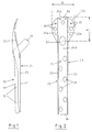
- the device 10 consists of a bone fastening tab 11 with a number of openings 12 formed therein for the passage of fastening screws if the device 10 is to be fastened to a bone with its bone fastening tab 11.
- the bone fastening tab 11 On one side, the bone fastening tab 11 carries a sleeve, a cylindrical tube or the like. 13, which to record and Guiding a bone nail or a bone screw, not shown in the drawing, the sleeve 13 is at an angle to the bone attachment tab 11, as shown in FIGS. 1 and 16.
- This device 10 with its bone fastening tab 11 and the sleeve 13 is combined according to FIGS. 1 and 16 with the trochanter support plate 20, which is a component in its own right in the form of a very specially designed molded body.
- This trochanter support plate 20 consists of a profile body 21 with a straight or a U-shaped cross section (FIGS. 3 and 4).
- the two legs forming the profile body 21 are designated by 22, 23 and the web connecting the two legs 22, 23 to one another is designated by 24.
- This profile body 21 has a tab-shaped section 29 which is formed by the legs 22, 23 and the web 24. This tab-shaped section 29 of the profile body 21 corresponds approximately to the shape and configuration of the bone attachment tab 11 of the device 10.
- a plate-shaped section 25 is formed on the web 24, which is widened like a head or shaped like a spoon and forms the support surface for the trochanter.
- This plate-shaped section 25 with its support surface for the trochanter forms the actual trochanter support plate.
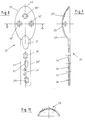
- This plate-shaped section 25, which forms the support surface for the trochanter is provided with a number of openings 30 which serve to receive and to pass through fastening nails or screws (FIG. 2).
- the trochanter support plate has 20 three openings 30 ', 30'', of which the two openings 30' are adjacent and preferably oval, while the third opening 30 '' is provided in the upper region of the trochanter support plate 20 and is circular.
- the web 24 or the tab-shaped section 29 of the profile body 21 of the trochanter support plate 20 has in its cross section an arcuate bulge 28, which is approximately adapted to the shape of the bone and which faces the two profile body legs 22, 23 (FIG. 4).
- the shape and dimensions of this bulge 28 correspond approximately to a section of the bulge of the bone, so that, if possible, a full-surface contact of the profile body 21 with its tab-shaped section 29 on a bone is ensured.
- the profile body 21 has in its web 24 and in particular in its tab-shaped section 29 a number of fastening openings 26 which, when the bone fastening tab 11 of the device 10 is inserted into the profile body 21 of the trochanter support plate 20 with the fastening openings 12 in the bone fastening tab 11 of the device 10 can be brought to cover, so that simultaneous attachment of the device 10 by means of its bone attachment tab 11 and the trochanter support plate 20 is possible.
- the fastening openings 26 in the web 24 or the tab-shaped section 29 of the profile body 21 of the trochanter support plate 20 extend into the area of the plate-shaped section 25 which forms the support surface for the trochanter (FIGS. 2 and 3).
- the legs 22, 23 of the profile body 21, as shown in FIG. 3, extend into the end region, which is indicated at 25a, of the plate-shaped section 25, which forms the support surface for the trochanter, the area in the region of the plate-shaped section 25 elongated sections of the two legs 22, 23 of the profile body 21 are indicated at 22a, 23a.
- These extended sections 22a, 23a of the legs 22, 23 of the profile body 21 of the trochanter support plate 20 taper conically towards their ends 22a ', 23a'.
- the extended sections 22a, 23a of the two legs 22, 23 in the region of the plate-shaped section 25 are adapted to the shape thereof (FIG. 3).
- the web 24 or the tab-shaped section 29 of the profile body 21 of the trochanter support plate 20 has an oval recess or opening 27 in the transition region to the plate-shaped section 25, which serves to lead through the sleeve 13 formed on the bone fastening tab 11 of the device 10 and is dimensioned such that devices 10 can also be used in connection with the trochanter support plate 20, in which there are different angular positions between the sleeve 13 and the bone fastening tab 11.
- the sleeve 13 or the supporting screw of the device 10 is passed through this oval recess or opening 27 when the device 10 is inserted into the trochanter support plate 20.
- the oval recess or opening 27 is therefore dimensioned such that tabs of all angles in relation to their sleeve 13 can be used.
- the dimensions of the trochanter supporting plate part 25 of the trochanter supporting plate 20 can be chosen arbitrarily. There is then the possibility of keeping a number of trochanter support plates 20 in stock, in which the plate part or plate-shaped section supporting the trochanter 25 can have different sizes, that is to say different dimensions, so that a maximum adaptability to anatomical conditions is always guaranteed if from A plurality of trochanter support plates 20 held in stock then use that trochanter support plate, the plate-shaped section 25 of which forms the support surface for the trochanter corresponds in its dimensions to the dimensions of the respective trochanter on which the trochanter support plate 20 in combination with the device 10 is brought into contact should.
- the advantage over the known devices, which are provided with a firmly formed trochanter support plate, is that the devices 10, which are associated with high production costs, do not have to be available in a very extensive range, but that the surgeon can manage with a small number of devices 10 if he has a larger number of trochanter support plates 20 with different shapes and adaptations of the plate-shaped section 25 and the support surface of the trochanter to form this trochanter support plate 20 in order to combine this trochanter support plate 20 with the corresponding device 10.
- the trochanter support plate 20 is made of high quality material which corresponds to the material from which the known devices are made. These are body-friendly materials, and suitable plastics can also be used if they meet the respective requirements such a trochanter support plate 20 can be provided.
- the dimensions of the profile body 21 of the trochanter support plate 20 in the region of its tab-shaped section 29 is such that the bone attachment tab 11 of the device 10 can be brought into contact with the profile leg web 24 between the two profile legs 22, 23.
- FIG. 5 shows such an extension element 40 with a short length
- the extension element according to FIG. 6 has a longer length.
- Each extension element 40 is plate and strip-shaped and corresponds in width approximately to the web 24 of the profile body 21 of the trochanter support plate 20.
- the extension element is provided with fastening openings 41.
- such an extension element 40 is placed on the web 24 and inserted between the two profile body legs 22, 23 so that the fastening openings 41 of the extension element 40 are congruent with the fastening openings 26 in the tab-shaped section 29 or the web 24 of the profile body 21 of the trochanter support plate 20 come to rest.
- guides (not shown in the drawing) in the region of the profile body legs 22, 23 or on the web 24 in order to be able to insert and hold such a plate-shaped extension element 40.
- the plate-shaped extension element 40 also has an arc profile corresponding to the arch profile of the web 24 of the profile body 21 of the trochanter support plate 20.
- the extension element 40 consists of the same materials from which the device 10 and the trochanter support plate 20 are made.
- the areas indicated by A 'and B' in FIG. 2 indicate the variability of the dimensions of the trochanter support surface.
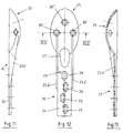
- the support surface of the trochanter support plate 20 is spoon-like and is provided on its rear region with reinforcing webs 22a ', 23a' which merge into the tab-shaped web 29 and which extend the extended sections 22a, 23a of the embodiment according to FIG 2 correspond and run on both sides of the longitudinal edges 29 ', 29' 'of the tab-shaped web 29 (FIGS. 12, 13, 15).
- These two stiffening webs 22a, 23a merge into the rounding of the spoon-like support surface of the trochanter support plate 20 and extend approximately to the two openings 30 'in the spoon-like support surface.
- the trochanter support plate 20 has an oval opening 27 in the transition region from the tab-shaped section 29 to the plate-shaped section 25, which lead through the sleeve 15 formed on the bone fastening tab 11 is used (FIGS. 12, 1 and 16).
- the openings 26 in the tab-shaped web 29 are arranged offset from one another, an arrangement of the openings 26 as shown in FIG. 8 being particularly advantageous, according to which the opening 26 facing the plate-shaped section 25 lies on the central longitudinal axis 60, while the other openings 26 are arranged alternately to the longitudinal axis 60 (Fig. 8).
- the trochanter support plate 20 has a connecting device 70, which enables a cerclage wire or several cerclage wires to be fixed to the trochanter support plate 20.
- This connection device 70 consists of an angling of the peripheral edge 125 of the plate-shaped and spoon-shaped section 25 of the trochanter support plate 20 in the rear region thereof.
- This angled, circumferential section 126 is essentially formed in the central side regions 125a, 125b of the circumferential edge 125 of the section 25 and thus extends to both sides of the section 25 of the trochanter support plate 20, so that two individual sections 126 ', 126''are formed .
- the ends of the two individual sections 126 ', 126''taper conically on both sides (Fig. 17).
- the angled section 126 or its individual sections 126 ', 126' ' have a number of slot-shaped recesses 129.
Landscapes
- Health & Medical Sciences (AREA)
- Orthopedic Medicine & Surgery (AREA)
- Surgery (AREA)
- Life Sciences & Earth Sciences (AREA)
- Heart & Thoracic Surgery (AREA)
- Nuclear Medicine, Radiotherapy & Molecular Imaging (AREA)
- Engineering & Computer Science (AREA)
- Biomedical Technology (AREA)
- Neurology (AREA)
- Medical Informatics (AREA)
- Molecular Biology (AREA)
- Animal Behavior & Ethology (AREA)
- General Health & Medical Sciences (AREA)
- Public Health (AREA)
- Veterinary Medicine (AREA)
- Surgical Instruments (AREA)
- Prostheses (AREA)
Priority Applications (1)
| Application Number | Priority Date | Filing Date | Title |
|---|---|---|---|
| AT89111280T ATE101990T1 (de) | 1988-06-24 | 1989-06-21 | Vorrichtung zum verbinden eines, insbesondere im bereich des oberschenkelhalses, gebrochenen knochens. |
Applications Claiming Priority (2)
| Application Number | Priority Date | Filing Date | Title |
|---|---|---|---|
| DE8808123U DE8808123U1 (de) | 1988-06-24 | 1988-06-24 | Laschenschraube für die Osteosynthese pertrochantärer Frakturen |
| DE8808123U | 1988-06-24 |
Publications (3)
| Publication Number | Publication Date |
|---|---|
| EP0347874A2 EP0347874A2 (de) | 1989-12-27 |
| EP0347874A3 EP0347874A3 (en) | 1990-05-09 |
| EP0347874B1 true EP0347874B1 (de) | 1994-03-02 |
Family
ID=6825308
Family Applications (1)
| Application Number | Title | Priority Date | Filing Date |
|---|---|---|---|
| EP89111280A Expired - Lifetime EP0347874B1 (de) | 1988-06-24 | 1989-06-21 | Vorrichtung zum Verbinden eines, insbesondere im Bereich des Oberschenkelhalses, gebrochenen Knochens |
Country Status (5)
| Country | Link |
|---|---|
| US (1) | US4988350A (es) |
| EP (1) | EP0347874B1 (es) |
| AT (1) | ATE101990T1 (es) |
| DE (2) | DE8808123U1 (es) |
| ES (1) | ES2050189T3 (es) |
Cited By (1)
| Publication number | Priority date | Publication date | Assignee | Title |
|---|---|---|---|---|
| US11179181B2 (en) | 2018-06-15 | 2021-11-23 | Stryker European Operations Holdings Llc | Trochanter plates |
Families Citing this family (128)
| Publication number | Priority date | Publication date | Assignee | Title |
|---|---|---|---|---|
| US5108397A (en) * | 1990-04-19 | 1992-04-28 | Joseph White | Method and apparatus for stabilization of pelvic fractures |
| US5207753A (en) * | 1991-02-18 | 1993-05-04 | Kannivelu Badrinath | Bone fracture repair apparatus and method |
| CH686222A5 (de) * | 1991-05-30 | 1996-02-15 | Synthes Ag | Trochanterstabilisierungsvorrichtung. |
| US5318567A (en) * | 1991-07-02 | 1994-06-07 | Olivier Vichard | Screw-on plate for treatment of fractures of the odontoid apophysis |
| US5356410A (en) * | 1991-12-13 | 1994-10-18 | Dietmar Pennig | Adjuvant for osteosynthesis in the case of pertrochanteric fracture of the neck of the femur |
| DE4141152C2 (de) * | 1991-12-13 | 1993-09-30 | Pennig Dietmar | Osteosynthesehilfsmittel bei pertrochantem Oberschenkelhalsbruch |
| US5304180A (en) * | 1992-01-17 | 1994-04-19 | Slocum D Barclay | Tibial osteotomy fixation plate |
| US5484439A (en) * | 1992-09-16 | 1996-01-16 | Alphatec Manufacturing, Inc. | Modular femur fixation device |
| US5429640A (en) * | 1992-11-27 | 1995-07-04 | Clemson University | Intramedullary rod for fracture fixation of femoral shaft independent of ipsilateral femoral neck fracture fixation |
| FR2712173A1 (fr) * | 1993-11-10 | 1995-05-19 | Fleuriau Chateau Joseph | Dispositif pour la réduction de fractures. |
| US5658339A (en) * | 1996-01-05 | 1997-08-19 | Wright Medical Technology, Inc. | Compression hip screw plate |
| US5938664A (en) | 1998-03-31 | 1999-08-17 | Zimmer, Inc. | Orthopaedic bone plate |
| US5993452A (en) * | 1998-08-24 | 1999-11-30 | Biomet Inc. | Cerclage system |
| US6183475B1 (en) * | 1998-12-18 | 2001-02-06 | Sulzer Orthopedics Inc. | Distal femoral osteotomy system and method |
| ATE274856T1 (de) * | 1999-03-09 | 2004-09-15 | Synthes Ag | Knochenplatte |
| ATE257674T1 (de) * | 1999-09-13 | 2004-01-15 | Synthes Ag | Knochenplattenvorrichtung |
| ES2253202T3 (es) | 2000-01-27 | 2006-06-01 | Synthes Ag Chur | Placa para osteosintesis. |
| US7857838B2 (en) | 2003-03-27 | 2010-12-28 | Depuy Products, Inc. | Anatomical distal radius fracture fixation plate |
| US7207993B1 (en) | 2000-02-03 | 2007-04-24 | Pioneer Laboratories, Inc. | Apparatus and method for repairing the femur |
| US6338734B1 (en) | 2000-03-14 | 2002-01-15 | Biomet, Inc. | Method and apparatus for trochanter fixation |
| PT1296603E (pt) * | 2000-05-31 | 2006-09-29 | Silvana Vese | Dispositivo para fixacao de segmentos osseos separados em virtude de uma fractura |
| RS49794B (sr) * | 2000-11-22 | 2008-06-05 | Milorad Mitković | Unutrašnji fiksator kostiju |
| DE10107369B4 (de) * | 2001-02-16 | 2016-03-24 | Ernst Wiedemann | Implantatplatte |
| US20020156474A1 (en) * | 2001-04-20 | 2002-10-24 | Michael Wack | Polyaxial locking plate |
| US20070055249A1 (en) * | 2003-06-20 | 2007-03-08 | Jensen David G | Bone plates with intraoperatively tapped apertures |
| US7717945B2 (en) * | 2002-07-22 | 2010-05-18 | Acumed Llc | Orthopedic systems |
| US7578825B2 (en) * | 2004-04-19 | 2009-08-25 | Acumed Llc | Placement of fasteners into bone |
| US7537596B2 (en) * | 2003-06-20 | 2009-05-26 | Acumed Llc | Bone plates with intraoperatively tapped apertures |
| US20050234458A1 (en) * | 2004-04-19 | 2005-10-20 | Huebner Randall J | Expanded stabilization of bones |
| US7537604B2 (en) * | 2002-11-19 | 2009-05-26 | Acumed Llc | Bone plates with slots |
| US20050240187A1 (en) * | 2004-04-22 | 2005-10-27 | Huebner Randall J | Expanded fixation of bones |
| AU2001258138B2 (en) | 2001-05-28 | 2004-10-28 | Synthes Gmbh | Bone plate for the fixation of fractures of the proximal humerus |
| SE522202C2 (sv) * | 2001-10-29 | 2004-01-20 | Gen Orthopedics Internat Ab | System för fixering av frakturer |
| USD463558S1 (en) | 2001-11-16 | 2002-09-24 | Zimmer, Inc. | Orthopaedic bone plate |
| USD464731S1 (en) | 2001-11-16 | 2002-10-22 | Zimmer, Inc. | Orthopaedic bone plate |
| US7938850B2 (en) * | 2002-05-30 | 2011-05-10 | Depuy Products, Inc. | Nail plate |
| US7780710B2 (en) | 2004-01-23 | 2010-08-24 | Depuy Products, Inc. | System for stabilization of fractures of convex articular bone surfaces including subchondral support structure |
| US20040116930A1 (en) * | 2002-06-10 | 2004-06-17 | O'driscoll Shawn W. | Bone plates |
| KR101081268B1 (ko) | 2002-07-22 | 2011-11-08 | 어큠드 엘엘씨 | 뼈 접합 기구체 |
| US7179260B2 (en) * | 2003-09-29 | 2007-02-20 | Smith & Nephew, Inc. | Bone plates and bone plate assemblies |
| AU2003294414B2 (en) | 2002-11-19 | 2009-03-12 | Acumed Llc | Deformable bone plates |
| JP4028552B2 (ja) | 2002-11-19 | 2007-12-26 | アキュームド・エルエルシー | 調節可能な骨プレート |
| WO2004045384A2 (en) * | 2002-11-19 | 2004-06-03 | Acumed Llc | Guide system for bone-repair devices |
| US7905883B2 (en) * | 2003-03-26 | 2011-03-15 | Greatbatch Medical S.A. | Locking triple pelvic osteotomy plate and method of use |
| EP1610700B1 (en) * | 2003-03-26 | 2010-08-04 | Swiss Orthopedic Solutions SA | Locking bone plate |
| US7722653B2 (en) * | 2003-03-26 | 2010-05-25 | Greatbatch Medical S.A. | Locking bone plate |
| GB0307648D0 (en) * | 2003-04-02 | 2003-05-07 | Benoist Girard Sas | Greater trochanter re-attachment device |
| US7776076B2 (en) * | 2004-05-11 | 2010-08-17 | Synthes Usa, Llc | Bone plate |
| US7951176B2 (en) | 2003-05-30 | 2011-05-31 | Synthes Usa, Llc | Bone plate |
| US20050131413A1 (en) * | 2003-06-20 | 2005-06-16 | O'driscoll Shawn W. | Bone plate with interference fit screw |
| US7135023B2 (en) * | 2003-07-07 | 2006-11-14 | Watkins William T | Compression bone screw device |
| US11259851B2 (en) | 2003-08-26 | 2022-03-01 | DePuy Synthes Products, Inc. | Bone plate |
| ES2348987T3 (es) | 2003-08-26 | 2010-12-21 | Synthes Gmbh | Placa para hueso. |
| US7635365B2 (en) | 2003-08-28 | 2009-12-22 | Ellis Thomas J | Bone plates |
| DE50308440D1 (de) * | 2003-09-08 | 2007-11-29 | Synthes Gmbh | Vorrichtung zur knochenfixation |
| MY130919A (en) * | 2003-09-19 | 2007-07-31 | Mattel Inc | Multidirectional light emitting diode unit |
| US8105367B2 (en) | 2003-09-29 | 2012-01-31 | Smith & Nephew, Inc. | Bone plate and bone plate assemblies including polyaxial fasteners |
| EP1677693B1 (de) * | 2003-10-30 | 2009-04-15 | Synthes GmbH | Knochenplatte |
| EP1691701B1 (de) * | 2003-11-18 | 2012-06-13 | Synthes GmbH | Osteosyntheseplatten-Set |
| CN103622741B (zh) | 2004-01-23 | 2016-12-07 | 拜欧米特公司 | 用于包括软骨下支撑结构的凸状关节骨表面骨折的稳定系统 |
| US8574268B2 (en) * | 2004-01-26 | 2013-11-05 | DePuy Synthes Product, LLC | Highly-versatile variable-angle bone plate system |
| US7637928B2 (en) * | 2004-01-26 | 2009-12-29 | Synthes Usa, Llc | Variable angle locked bone fixation system |
| US11291484B2 (en) | 2004-01-26 | 2022-04-05 | DePuy Synthes Products, Inc. | Highly-versatile variable-angle bone plate system |
| WO2005074580A2 (en) * | 2004-02-02 | 2005-08-18 | Acumed Llc | Bone plate with toothed aperture |
| WO2006091827A2 (en) * | 2005-02-25 | 2006-08-31 | Regents Of The University Of California | Device and template for canine humeral slide osteotomy |
| US20080045960A1 (en) * | 2004-03-25 | 2008-02-21 | Bruecker Kenneth | Locking tpo plate and method of use |
| EP1727484A2 (en) * | 2004-03-26 | 2006-12-06 | Smith and Nephew, Inc. | Methods for treating fractures of the femur and femoral fracture devices |
| US7229445B2 (en) * | 2004-06-21 | 2007-06-12 | Synthes (Usa) | Bone plate with bladed portion |
| US7229444B2 (en) * | 2004-08-25 | 2007-06-12 | Howmedica Osteonics Corp. | Trochanteric cerclage plate |
| US20060173458A1 (en) * | 2004-10-07 | 2006-08-03 | Micah Forstein | Bone fracture fixation system |
| EP1855605B1 (en) * | 2005-01-28 | 2014-01-08 | Biomet C.V. | Nail plate system |
| JP5270339B2 (ja) | 2005-07-25 | 2013-08-21 | スミス アンド ネフュー インコーポレーテッド | 多軸プレートを使用するためのシステムおよび方法 |
| US8382807B2 (en) | 2005-07-25 | 2013-02-26 | Smith & Nephew, Inc. | Systems and methods for using polyaxial plates |
| US8177818B2 (en) * | 2005-09-08 | 2012-05-15 | Securos, Inc. | Fixation plate |
| US8523921B2 (en) | 2006-02-24 | 2013-09-03 | DePuy Synthes Products, LLC | Tibial plateau leveling osteotomy plate |
| US8808334B2 (en) * | 2006-03-07 | 2014-08-19 | Orthohelix Surgical Designs, Inc. | Orthopedic plate |
| US8021402B2 (en) * | 2006-03-07 | 2011-09-20 | Orthohelix Surgical Designs, Inc. | Distal radius plate |
| US20080086137A1 (en) * | 2006-10-04 | 2008-04-10 | Robert Probe | Fixation of femoral neck fractures |
| GB2450247B (en) * | 2007-06-15 | 2010-01-13 | Joel Gillard | Rib fixation with an intramedullary nail |
| FR2936700B1 (fr) * | 2008-10-02 | 2012-04-13 | Memometal Technologies | Implant orthopedique sous forme d'une plaque destinee a etre fixee entre deux parties d'os |
| US9237910B2 (en) | 2012-01-26 | 2016-01-19 | Acute Innovations Llc | Clip for rib stabilization |
| US12285197B2 (en) | 2008-10-10 | 2025-04-29 | Acumed Llc | Bone fixation system with opposed mounting portions |
| ES2645888T3 (es) | 2009-01-16 | 2017-12-11 | Carbofix Orthopedics Ltd. | Implante óseo de material de composite |
| US8808333B2 (en) | 2009-07-06 | 2014-08-19 | Zimmer Gmbh | Periprosthetic bone plates |
| US9668868B2 (en) | 2009-08-27 | 2017-06-06 | Cotera, Inc. | Apparatus and methods for treatment of patellofemoral conditions |
| ES2477581T3 (es) * | 2009-08-27 | 2014-07-17 | Cotera, Inc. | Aparato para la redistribución de fuerzas en uniones articulares |
| US10349980B2 (en) | 2009-08-27 | 2019-07-16 | The Foundry, Llc | Method and apparatus for altering biomechanics of the shoulder |
| US9861408B2 (en) | 2009-08-27 | 2018-01-09 | The Foundry, Llc | Method and apparatus for treating canine cruciate ligament disease |
| US9278004B2 (en) * | 2009-08-27 | 2016-03-08 | Cotera, Inc. | Method and apparatus for altering biomechanics of the articular joints |
| RU2012108851A (ru) * | 2009-09-14 | 2013-10-27 | Зинтес Гмбх | Компрессионная пластинка с вариабельным углом |
| CA2688903C (en) * | 2009-12-18 | 2017-08-29 | Shahryar Ahmadi | Bone fixation system |
| US8568417B2 (en) | 2009-12-18 | 2013-10-29 | Charles River Engineering Solutions And Technologies, Llc | Articulating tool and methods of using |
| FR2956972B1 (fr) * | 2010-03-08 | 2012-12-28 | Memometal Technologies | Plaque d'osteosynthese articulee |
| FR2956971B1 (fr) | 2010-03-08 | 2012-03-02 | Memometal Technologies | Systeme d'osteosynthese a plaque |
| CN105877829B (zh) | 2010-06-07 | 2018-06-22 | 卡波菲克斯整形有限公司 | 复合材料骨植入物 |
| US10154867B2 (en) | 2010-06-07 | 2018-12-18 | Carbofix In Orthopedics Llc | Multi-layer composite material bone screw |
| WO2012021354A1 (en) * | 2010-08-13 | 2012-02-16 | Synthes Usa, Llc | Bone stabilization device |
| KR101219266B1 (ko) * | 2010-08-13 | 2013-01-18 | 박지선 | 대퇴골 소전자와 주위를 견고하게 고정시켜서 인공 고관절 치환술이 가능할 수 있도록 안정적으로 보강하는 소전자 고정 장치 |
| US8523861B2 (en) | 2010-08-30 | 2013-09-03 | Biomet Manufacturing, Llc | Method and apparatus for osteosynthesis |
| US20120323284A1 (en) | 2011-06-15 | 2012-12-20 | Smith & Nephew, Inc. | Variable angle locking implant |
| DE102011116732A1 (de) | 2011-09-02 | 2013-03-07 | Königsee Implantate GmbH | Vorrichtung zum Fixieren eines im Bereich des Oberschenkelhalses frakturierten Knochens |
| GB2509668B (en) | 2011-09-30 | 2018-04-11 | Acute Innovations Llc | Bone fixation system with opposed mounting portions |
| US9730797B2 (en) | 2011-10-27 | 2017-08-15 | Toby Orthopaedics, Inc. | Bone joint replacement and repair assembly and method of repairing and replacing a bone joint |
| US20130184765A1 (en) * | 2012-01-16 | 2013-07-18 | Carbofix Orthopedics Ltd. | Multi-axial bone plate fixation |
| US9526549B2 (en) | 2012-01-16 | 2016-12-27 | Carbofix Orthopedics Ltd. | Bone screw with insert |
| US9468466B1 (en) | 2012-08-24 | 2016-10-18 | Cotera, Inc. | Method and apparatus for altering biomechanics of the spine |
| CN103610494A (zh) * | 2013-12-13 | 2014-03-05 | 李照文 | 一种带弧形板的接骨板 |
| US9956015B2 (en) | 2014-07-03 | 2018-05-01 | Acumed Llc | Bone plate with movable joint |
| GB2532721B (en) | 2014-11-21 | 2021-02-10 | Everost Uk Ltd | Bone fixation plate |
| TW201620456A (zh) * | 2014-12-01 | 2016-06-16 | 愛派司生技股份有限公司 | 一種用於髖部骨折之固定裝置 |
| US9339313B1 (en) | 2015-05-20 | 2016-05-17 | Roy Y. Powlan | Hip fracture support plate |
| US10993750B2 (en) | 2015-09-18 | 2021-05-04 | Smith & Nephew, Inc. | Bone plate |
| US10617458B2 (en) | 2015-12-23 | 2020-04-14 | Carbofix In Orthopedics Llc | Multi-layer composite material bone screw |
| CN105640635B (zh) * | 2016-02-03 | 2018-08-31 | 哈尔滨医科大学 | 一种股骨假体周围骨折翻修锁定钢板 |
| US10624686B2 (en) | 2016-09-08 | 2020-04-21 | DePuy Synthes Products, Inc. | Variable angel bone plate |
| US10820930B2 (en) | 2016-09-08 | 2020-11-03 | DePuy Synthes Products, Inc. | Variable angle bone plate |
| US10905476B2 (en) | 2016-09-08 | 2021-02-02 | DePuy Synthes Products, Inc. | Variable angle bone plate |
| CN106618719B (zh) * | 2017-01-11 | 2023-04-18 | 海口市人民医院 | 经后侧股骨小粗隆复位空心拉力螺钉导针瞄准固定器 |
| CA3078249A1 (en) | 2017-10-11 | 2019-04-18 | Tornier, Inc. | Humeral fixation plate guides |
| US11026727B2 (en) | 2018-03-20 | 2021-06-08 | DePuy Synthes Products, Inc. | Bone plate with form-fitting variable-angle locking hole |
| US10772665B2 (en) | 2018-03-29 | 2020-09-15 | DePuy Synthes Products, Inc. | Locking structures for affixing bone anchors to a bone plate, and related systems and methods |
| US11013541B2 (en) | 2018-04-30 | 2021-05-25 | DePuy Synthes Products, Inc. | Threaded locking structures for affixing bone anchors to a bone plate, and related systems and methods |
| US10925651B2 (en) | 2018-12-21 | 2021-02-23 | DePuy Synthes Products, Inc. | Implant having locking holes with collection cavity for shavings |
| CN109620379B (zh) * | 2018-12-26 | 2021-04-30 | 创美得医疗器械(天津)有限公司 | 骨骼复位固定夹板 |
| US11523824B2 (en) * | 2019-12-12 | 2022-12-13 | Covidien Lp | Anvil buttress loading for a surgical stapling apparatus |
| US11963847B2 (en) | 2021-11-03 | 2024-04-23 | DePuy Synthes Products, Inc. | TPLO plate compression system and method |
| US12402923B2 (en) | 2022-10-04 | 2025-09-02 | DePuy Synthes Products, Inc. | Offset hole for TPLO compression |
| US12502211B1 (en) | 2025-01-17 | 2025-12-23 | Tplo Company Llc | Implant device for a tibial plateau leveling osteotomy |
Family Cites Families (15)
| Publication number | Priority date | Publication date | Assignee | Title |
|---|---|---|---|---|
| US2443363A (en) * | 1942-04-13 | 1948-06-15 | Townsend Kenneth | Bone plate |
| US2496126A (en) * | 1947-10-28 | 1950-01-31 | Edward J Haboush | Fracture nail and bone plate |
| US2772676A (en) * | 1951-12-06 | 1956-12-04 | Pohl Ernst | Connecting device for bone fractures in the neighborhood of joints |
| US2699774A (en) * | 1952-05-12 | 1955-01-18 | Livingston Herman Harrison | Bone pin locking device |
| US2801631A (en) * | 1954-08-18 | 1957-08-06 | Charnley John | Fracture screw adjusting means |
| DE1046827B (de) * | 1955-10-18 | 1958-12-18 | Med H C Ernst Pohl Dr | Verbindungsvorrichtung fuer gelenknahe Knochenbrueche |
| US3489143A (en) * | 1967-12-15 | 1970-01-13 | William X Halloran | Convertible hip pin |
| DE2030249A1 (de) * | 1970-06-19 | 1971-12-30 | Fischer, Artur, 7241 Tumlingen | Vorrichtimg zur Verbindung von Knochenfragmenten |
| FR2149943A5 (es) * | 1971-08-17 | 1973-03-30 | Fischer Artur | |
| US3842825A (en) * | 1973-11-12 | 1974-10-22 | R Wagner | Hip fixation device |
| DE3006518C2 (de) * | 1980-02-19 | 1982-08-05 | Mecron Medizinische Produkte Gmbh, 1000 Berlin | Vorrichtung zum Fixieren des Oberschenkelhalses und des großen Rollhügels am Schaft eines Oberschenkelknochens |
| US4438762A (en) * | 1981-12-30 | 1984-03-27 | Richard F. Kyle | Orthopedic hip fixation device |
| US4628923A (en) * | 1983-11-28 | 1986-12-16 | Medoff Robert J | Axial compression device |
| US4621629A (en) * | 1985-08-12 | 1986-11-11 | Harrington Arthritis Research Center | Compression hip screw |
| DE3534747A1 (de) * | 1985-09-28 | 1987-04-09 | Hasselbach Christoph Von | Schenkelhalsimplantat |
-
1988
- 1988-06-24 DE DE8808123U patent/DE8808123U1/de not_active Expired
-
1989
- 1989-06-21 EP EP89111280A patent/EP0347874B1/de not_active Expired - Lifetime
- 1989-06-21 ES ES89111280T patent/ES2050189T3/es not_active Expired - Lifetime
- 1989-06-21 AT AT89111280T patent/ATE101990T1/de active
- 1989-06-21 DE DE89111280T patent/DE58907062D1/de not_active Expired - Fee Related
- 1989-06-23 US US07/370,610 patent/US4988350A/en not_active Expired - Fee Related
Cited By (1)
| Publication number | Priority date | Publication date | Assignee | Title |
|---|---|---|---|---|
| US11179181B2 (en) | 2018-06-15 | 2021-11-23 | Stryker European Operations Holdings Llc | Trochanter plates |
Also Published As
| Publication number | Publication date |
|---|---|
| EP0347874A3 (en) | 1990-05-09 |
| DE8808123U1 (de) | 1988-09-22 |
| ES2050189T3 (es) | 1994-05-16 |
| US4988350A (en) | 1991-01-29 |
| DE58907062D1 (de) | 1994-04-07 |
| ATE101990T1 (de) | 1994-03-15 |
| EP0347874A2 (de) | 1989-12-27 |
Similar Documents
| Publication | Publication Date | Title |
|---|---|---|
| EP0347874B1 (de) | Vorrichtung zum Verbinden eines, insbesondere im Bereich des Oberschenkelhalses, gebrochenen Knochens | |
| EP0592897B1 (de) | Modularer Hüftprothesenschaft | |
| EP0542004B1 (de) | Stützmittel für die menschliche Wirbelsäule | |
| DE60014042T2 (de) | Axialer äusserer Fixateur | |
| DE69419412T2 (de) | Osteosyntheseklammer und hilfsinstrumente zu ihrer befestigung | |
| DE69525124T2 (de) | Befestigungsplatte und Knochenschraube | |
| DE69510516T2 (de) | Osteosynthetisches Gerät zur Befestigung und/oder longitudinalen Ausrichtung | |
| DE3751339T2 (de) | Komponenten eines Modulsystems zum Fixieren des Femurs. | |
| DE69314334T2 (de) | Vorrichtung zur osteosynthese von rückenwirbeln | |
| EP1339335B1 (de) | Vorrichtung zur fixation von knochen, insbesondere von wirbelkörpern relativ zueinander | |
| DE69915254T2 (de) | Knochenschraube für orthopädische Chirurgie | |
| EP1684651A1 (de) | Platte zum stabilisieren distaler radiusfrakturen | |
| EP1024762A1 (de) | Knochenfixationsvorrichtung | |
| DE3021238A1 (de) | Anordnung mit hakenfoermigen elementen | |
| DE3538645C2 (es) | ||
| EP0423280B1 (de) | Fixierungssystem für röhrenknochenfrakturen | |
| EP1330988B1 (de) | Intramedulläres Osteosyntheseimplantat | |
| DE10335388A1 (de) | Chirurgische Referenzierungsvorrichtung | |
| EP1572018A2 (de) | Knochennagel zum versorgen von frakturen | |
| DE20200705U1 (de) | Intramedulläres Osteosyntheseimplantat | |
| DE10356904B4 (de) | Platte zum Stabilisieren distaler Radiusfrakturen | |
| DE69618591T2 (de) | Mehrrichtungs-mandibulare Streckvorrichtung | |
| EP3616636B1 (de) | Knochenplatte und chirurgische sets | |
| EP2029037B1 (de) | Femurkopf-implantat | |
| EP1364621A1 (de) | Vorrichtung zum Positionieren und Fixieren von Knochen und/oder Knochenfragmenten |
Legal Events
| Date | Code | Title | Description |
|---|---|---|---|
| PUAI | Public reference made under article 153(3) epc to a published international application that has entered the european phase |
Free format text: ORIGINAL CODE: 0009012 |
|
| AK | Designated contracting states |
Kind code of ref document: A2 Designated state(s): AT BE CH DE ES FR GB GR IT LI NL SE |
|
| PUAL | Search report despatched |
Free format text: ORIGINAL CODE: 0009013 |
|
| RAP1 | Party data changed (applicant data changed or rights of an application transferred) |
Owner name: VOSS, GUDRUN Owner name: DUNSCH-HERZBERG, RENATE |
|
| RIN1 | Information on inventor provided before grant (corrected) |
Inventor name: HERZBERG, WOLFGANG, DR.MED. |
|
| AK | Designated contracting states |
Kind code of ref document: A3 Designated state(s): AT BE CH DE ES FR GB GR IT LI NL SE |
|
| 17P | Request for examination filed |
Effective date: 19900414 |
|
| 17Q | First examination report despatched |
Effective date: 19921106 |
|
| ITF | It: translation for a ep patent filed | ||
| GRAA | (expected) grant |
Free format text: ORIGINAL CODE: 0009210 |
|
| AK | Designated contracting states |
Kind code of ref document: B1 Designated state(s): AT BE CH DE ES FR GB GR IT LI NL SE |
|
| REF | Corresponds to: |
Ref document number: 101990 Country of ref document: AT Date of ref document: 19940315 Kind code of ref document: T |
|
| GBT | Gb: translation of ep patent filed (gb section 77(6)(a)/1977) |
Effective date: 19940224 |
|
| RAP2 | Party data changed (patent owner data changed or rights of a patent transferred) |
Owner name: VOSS, GUDRUN Owner name: DUNSCH-HERZBERG, RENATE |
|
| ET | Fr: translation filed | ||
| REF | Corresponds to: |
Ref document number: 58907062 Country of ref document: DE Date of ref document: 19940407 |
|
| REG | Reference to a national code |
Ref country code: ES Ref legal event code: FG2A Ref document number: 2050189 Country of ref document: ES Kind code of ref document: T3 |
|
| PGFP | Annual fee paid to national office [announced via postgrant information from national office to epo] |
Ref country code: GR Payment date: 19940608 Year of fee payment: 6 Ref country code: BE Payment date: 19940608 Year of fee payment: 6 |
|
| PGFP | Annual fee paid to national office [announced via postgrant information from national office to epo] |
Ref country code: SE Payment date: 19940609 Year of fee payment: 6 |
|
| PGFP | Annual fee paid to national office [announced via postgrant information from national office to epo] |
Ref country code: NL Payment date: 19940630 Year of fee payment: 6 |
|
| REG | Reference to a national code |
Ref country code: GR Ref legal event code: FG4A Free format text: 3012011 |
|
| PLBE | No opposition filed within time limit |
Free format text: ORIGINAL CODE: 0009261 |
|
| STAA | Information on the status of an ep patent application or granted ep patent |
Free format text: STATUS: NO OPPOSITION FILED WITHIN TIME LIMIT |
|
| EAL | Se: european patent in force in sweden |
Ref document number: 89111280.7 |
|
| 26N | No opposition filed | ||
| PG25 | Lapsed in a contracting state [announced via postgrant information from national office to epo] |
Ref country code: SE Effective date: 19950622 |
|
| PG25 | Lapsed in a contracting state [announced via postgrant information from national office to epo] |
Ref country code: BE Effective date: 19950630 |
|
| BERE | Be: lapsed |
Owner name: VOSS GUDRUN Effective date: 19950630 Owner name: DUNSCH-HERZBERG RENATE Effective date: 19950630 |
|
| PG25 | Lapsed in a contracting state [announced via postgrant information from national office to epo] |
Ref country code: GR Free format text: THE PATENT HAS BEEN ANNULLED BY A DECISION OF A NATIONAL AUTHORITY Effective date: 19951231 |
|
| PG25 | Lapsed in a contracting state [announced via postgrant information from national office to epo] |
Ref country code: NL Effective date: 19960101 |
|
| REG | Reference to a national code |
Ref country code: GR Ref legal event code: MM2A Free format text: 3012011 |
|
| NLV4 | Nl: lapsed or anulled due to non-payment of the annual fee |
Effective date: 19960101 |
|
| EUG | Se: european patent has lapsed |
Ref document number: 89111280.7 |
|
| PGFP | Annual fee paid to national office [announced via postgrant information from national office to epo] |
Ref country code: CH Payment date: 19980522 Year of fee payment: 10 |
|
| PGFP | Annual fee paid to national office [announced via postgrant information from national office to epo] |
Ref country code: AT Payment date: 19980630 Year of fee payment: 10 |
|
| PG25 | Lapsed in a contracting state [announced via postgrant information from national office to epo] |
Ref country code: AT Free format text: LAPSE BECAUSE OF NON-PAYMENT OF DUE FEES Effective date: 19990621 |
|
| PG25 | Lapsed in a contracting state [announced via postgrant information from national office to epo] |
Ref country code: LI Free format text: LAPSE BECAUSE OF NON-PAYMENT OF DUE FEES Effective date: 19990630 Ref country code: CH Free format text: LAPSE BECAUSE OF NON-PAYMENT OF DUE FEES Effective date: 19990630 |
|
| REG | Reference to a national code |
Ref country code: CH Ref legal event code: PL |
|
| PGFP | Annual fee paid to national office [announced via postgrant information from national office to epo] |
Ref country code: ES Payment date: 20000620 Year of fee payment: 12 |
|
| PGFP | Annual fee paid to national office [announced via postgrant information from national office to epo] |
Ref country code: GB Payment date: 20000627 Year of fee payment: 12 |
|
| PGFP | Annual fee paid to national office [announced via postgrant information from national office to epo] |
Ref country code: FR Payment date: 20000629 Year of fee payment: 12 |
|
| PG25 | Lapsed in a contracting state [announced via postgrant information from national office to epo] |
Ref country code: GB Free format text: LAPSE BECAUSE OF NON-PAYMENT OF DUE FEES Effective date: 20010621 |
|
| PG25 | Lapsed in a contracting state [announced via postgrant information from national office to epo] |
Ref country code: ES Free format text: LAPSE BECAUSE OF NON-PAYMENT OF DUE FEES Effective date: 20010622 |
|
| GBPC | Gb: european patent ceased through non-payment of renewal fee |
Effective date: 20010621 |
|
| PG25 | Lapsed in a contracting state [announced via postgrant information from national office to epo] |
Ref country code: FR Free format text: LAPSE BECAUSE OF NON-PAYMENT OF DUE FEES Effective date: 20020228 |
|
| REG | Reference to a national code |
Ref country code: ES Ref legal event code: FD2A Effective date: 20030303 |
|
| PGFP | Annual fee paid to national office [announced via postgrant information from national office to epo] |
Ref country code: DE Payment date: 20040819 Year of fee payment: 16 |
|
| PG25 | Lapsed in a contracting state [announced via postgrant information from national office to epo] |
Ref country code: IT Free format text: LAPSE BECAUSE OF NON-PAYMENT OF DUE FEES;WARNING: LAPSES OF ITALIAN PATENTS WITH EFFECTIVE DATE BEFORE 2007 MAY HAVE OCCURRED AT ANY TIME BEFORE 2007. THE CORRECT EFFECTIVE DATE MAY BE DIFFERENT FROM THE ONE RECORDED. Effective date: 20050621 |
|
| PG25 | Lapsed in a contracting state [announced via postgrant information from national office to epo] |
Ref country code: DE Free format text: LAPSE BECAUSE OF NON-PAYMENT OF DUE FEES Effective date: 20060103 |