EP1610700B1 - Locking bone plate - Google Patents
Locking bone plate Download PDFInfo
- Publication number
- EP1610700B1 EP1610700B1 EP04723661A EP04723661A EP1610700B1 EP 1610700 B1 EP1610700 B1 EP 1610700B1 EP 04723661 A EP04723661 A EP 04723661A EP 04723661 A EP04723661 A EP 04723661A EP 1610700 B1 EP1610700 B1 EP 1610700B1
- Authority
- EP
- European Patent Office
- Prior art keywords
- plate
- bone plate
- overlapping
- bone
- holes
- Prior art date
- Legal status (The legal status is an assumption and is not a legal conclusion. Google has not performed a legal analysis and makes no representation as to the accuracy of the status listed.)
- Revoked
Links
Images


Classifications
-
- A—HUMAN NECESSITIES
- A61—MEDICAL OR VETERINARY SCIENCE; HYGIENE
- A61B—DIAGNOSIS; SURGERY; IDENTIFICATION
- A61B17/00—Surgical instruments, devices or methods, e.g. tourniquets
- A61B17/56—Surgical instruments or methods for treatment of bones or joints; Devices specially adapted therefor
- A61B17/58—Surgical instruments or methods for treatment of bones or joints; Devices specially adapted therefor for osteosynthesis, e.g. bone plates, screws, setting implements or the like
- A61B17/68—Internal fixation devices, including fasteners and spinal fixators, even if a part thereof projects from the skin
- A61B17/80—Cortical plates, i.e. bone plates; Instruments for holding or positioning cortical plates, or for compressing bones attached to cortical plates
- A61B17/8052—Cortical plates, i.e. bone plates; Instruments for holding or positioning cortical plates, or for compressing bones attached to cortical plates immobilised relative to screws by interlocking form of the heads and plate holes, e.g. conical or threaded
-
- A—HUMAN NECESSITIES
- A61—MEDICAL OR VETERINARY SCIENCE; HYGIENE
- A61B—DIAGNOSIS; SURGERY; IDENTIFICATION
- A61B17/00—Surgical instruments, devices or methods, e.g. tourniquets
- A61B17/16—Bone cutting, breaking or removal means other than saws, e.g. Osteoclasts; Drills or chisels for bones; Trepans
- A61B17/17—Guides or aligning means for drills, mills, pins or wires
- A61B17/1728—Guides or aligning means for drills, mills, pins or wires for holes for bone plates or plate screws
-
- A—HUMAN NECESSITIES
- A61—MEDICAL OR VETERINARY SCIENCE; HYGIENE
- A61B—DIAGNOSIS; SURGERY; IDENTIFICATION
- A61B17/00—Surgical instruments, devices or methods, e.g. tourniquets
- A61B17/56—Surgical instruments or methods for treatment of bones or joints; Devices specially adapted therefor
- A61B17/58—Surgical instruments or methods for treatment of bones or joints; Devices specially adapted therefor for osteosynthesis, e.g. bone plates, screws, setting implements or the like
- A61B17/68—Internal fixation devices, including fasteners and spinal fixators, even if a part thereof projects from the skin
- A61B17/80—Cortical plates, i.e. bone plates; Instruments for holding or positioning cortical plates, or for compressing bones attached to cortical plates
- A61B17/8052—Cortical plates, i.e. bone plates; Instruments for holding or positioning cortical plates, or for compressing bones attached to cortical plates immobilised relative to screws by interlocking form of the heads and plate holes, e.g. conical or threaded
- A61B17/8057—Cortical plates, i.e. bone plates; Instruments for holding or positioning cortical plates, or for compressing bones attached to cortical plates immobilised relative to screws by interlocking form of the heads and plate holes, e.g. conical or threaded the interlocking form comprising a thread
-
- A—HUMAN NECESSITIES
- A61—MEDICAL OR VETERINARY SCIENCE; HYGIENE
- A61B—DIAGNOSIS; SURGERY; IDENTIFICATION
- A61B50/00—Containers, covers, furniture or holders specially adapted for surgical or diagnostic appliances or instruments, e.g. sterile covers
- A61B50/30—Containers specially adapted for packaging, protecting, dispensing, collecting or disposing of surgical or diagnostic appliances or instruments
Definitions
- This invention relates to devices, implants and prostheses used in orthopedic surgery, and, more particularly, to bone plates used to reinforce fractured bones and thus promote healing.
- a compressive screw system also known as the DCS system
- DCS system is a bone plate system that has been used in trauma surgery for many years.
- the procedures for use of this system are well documented by the AO Institute, an institute having as one of its goals, the promotion of new orthopaedic surgical procedures.
- This system included a bone plate having slots communicating therethrough.
- a land in which the slot is wider at one end defines a stepped surface adjacent the portion of the slot that extends through the bone plate.
- the stepped surface is generally cut with a spherical endmill, thus creating a spherical stepped surface.
- bone plates have been developed having individual threaded apertures and non-threaded apertures interspersed along the length of the plate.
- the distance between holes has become a standard.
- expandable, lockable inserts enter into the slots of a standard bone plate. When the bone screw passes through one of these inserts and is torqued down, the insert expands and locks the screw in place. However, this insert is locked in a secondary operation. This is not desirable because this requires more operating room time and adds complexity to the procedure. Further, the inserts must be added in the specific location before the plate is fixed to the bone and cannot be subsequently inserted. This limits the choice of placement during surgery if the need arises.
- an osteosynthetic pressure plate having a cross-section transverse to the longitudinal axis of the plate at at least one point being wider toward the upper surface than toward the lower surface and the plate having recesses in the lower surface so that upon application to a bone there is space between the bone and the plate.
- the cross-section between the screw holes is reduced, preferably to the extent that the resistance of the plate to bending in this area is less than in the area of the holes. Because of the reduced bend resistance between the holes, the plate can more easily be adapted to conform to the anatomy of the bone. Furthermore, this can be done without deformation of the holes, thus minimizing the resulting loss of fatigue strength and minimizing the misfit of the screw heads.
- US Patent No. 5,709,686 to Takos et al describes a bone plate that has recesses or reduced thickness portions on its sides, between threaded apertures. Although the purpose is not specifically described, these recesses appear to function to avoid warpage of the threaded portions when the bone plate is bent. However, when such a bone plate is fixed to a bone, these discontinuous recesses are exposed and may potentially come into contact with and potentially aggrevate muscle tissue.
- US Patent No. 5,733,287 to Tepic et al shows (in figure 4 ), a plate that has transverse cuts 13 and a longitudinal cut 14 on the lower surface 7 to reduce contact between the plate and bone. Due to the transverse undercuts 13, the cross-section 15 between the holes is already significantly reduced and therefore is not further decreased by an additional groove 10 on the upper surface 6 as in the embodiment according to figure 3 . To avoid a cross-section that is too thin, the groove 10 on the upper surface 6 is made discontinuous in short segmental grooves 16 providing a smooth transition into and out of the holes 8.
- PCT application no. WO01/54601 combines the features of the DCS system discussed above with a locking screw.
- This design combines the features of the DCS system with a locking screw.
- Such a system is known as the combi-slot.
- the stepped surface of the slot is generally ramped or tapered so as to be deeper at one end than at another. This enables the positioning and selective fixing of the bone plate for compressing two bone fragments together with a preload created by wedging action. In this manner, the bones are placed in a position that the surgeon believes would best promote healing.
- this combi-hole includes two distinct overlapping portions in a single slot.
- One portion of the slot is suited to receive a standard bone screw, while the other portion of the slot is suited to receive a threaded peg oriented perpendicular to the top surface of the bone plate.
- the combi-holes are generally oriented with the threaded portions being on the innermost end of the combination and the unthreaded portions oriented toward the ends of the bone plate. This improvement increased the flexibility of choice available to orthopaedic surgeons using the device in that it was more likely that a hole would be present at a suitable anchoring point in the bone plate. Nevertheless, there are often trauma situations that are best served by the threaded portion being at the extreme ends of the bone plate and/or at various positions throughout the plate. In addition, sometimes there is no specific center of the facture -in such a situation, use of the combi-hole design is limited.
- German patent DE 4341980 A1 published on June 14, 1995 , describes a bone plate 2 having an elongated slot 8 in which the sidewalls of the long sides of the slot are not parallel and are further provided with an internal thread 9.
- Corresponding bone screws 3 or inserts 6 have a head 5 with an external taper 4 and thus can be fixed into any point along the length, but to various depths of penetration. Therefore, the final configuration upon fixing is indeterminate and, due to the small amount of contact between the threads of the insert or screw and the slot, as well as the fact that the screw will be able to slide in one direction, the design does not appear to lend itself to reliable fixing.
- US Patent No. 5,324,290 shows a complex bone plate having slots with countersunk circular recessed cut at intervals along the slot (a similar arrangement is shown in US Patent No. 4,696,290 ). It further shows the bone plate torqued against the bone so as to at least marginally, conform to the shape of the bone (see Fig. 2 ).
- Other patents of interest include US Patent No. 3,716,050 , 3,659,595 , 5,681,311 , 5,261,910 , and 5,364,399 , all showing combinations of conventional slots and recesses which do not fully accommodate a bone screw having a threaded head.
- a bone plate that provides greater flexibility of choice to the surgeon. More specifically, what is needed is a bone plate that provides this choice of plate placement while reliably and permanently fixing the bone plate to the bone fragments, in any hole position.
- What is needed is a bone plate that provides greater flexibility of choice to the surgeon, in a bone plate that has multiple orientations for the locking screw and thus, plate placement, while reliably and permanently fixing the bone plate to the bone fragments, in any hole position.
- a bone plate having a longitudinal axis, a bone-contacting bottom side and a top side.
- Sets of overlapping holes communicate through the plate from the top to the bottom side.
- the overlapping holes have multifaceted surfaces such as a threaded surface or a coaxial series of annular grooves.
- the sets of overlapping holes are adapted to receive a bone screw with a head and a bone-engaging thread.
- An object of the invention is to provide an orthopaedic surgeon greater flexibity of choice in that a threaded peg providing secure fixing can be positioned at any interval along the bone plate, including at its extreme ends.
- a bone plate 10 with a longitudinal axis 12 has a bone-contacting bottom side 14 and a top side 16.
- Multiple sets 20 of overlapping holes 22 communicate through the plate 10 from the top side 16 to the bottom side 14.
- the overlapping holes 22 are adapted to receive a bone screw 24 with a head 26 having a thread 30 and, on an opposite end 32, a body having a bone-engaging thread 34 (shown in FIG. 8 ).
- the multiple sets 20 of overlapping holes 22 allow for further adjustability and flexibility in positioning of the bone plate 10 during surgery.
- the overlapping holes 22 are formed normal to the top side 16 of the plate 10 (shown in FIGS. 1c and 1d ).
- the overlapping holes 22 have multifaceted surfaces 36.
- the multifaceted surface 36 is a threaded surface 40 (shown in FIG. 2a ).
- the multi-faceted surface 36 is a coaxial series of annular grooves 42 (shown in FIG. 2b ).
- Overlapping holes 22 are formed individually at an angle 0 offset from normal to the top side 16 of the plate 10. Such allows further flexibility of choice to the surgeon as to where and how to fasten the bone plate 10. Referring again to FIGS. 1c and 1d , where these overlapping holes 22 are oriented perpendicularly to the top side 16 of the bone plate 10, he may chose to fasten the plates in a conventional manner, namely, perpendicular to the top side of the plate.
- some of the overlapping holes 22 are formed normal to the top side 16 of the plate 10.
- all of the overlapping holes 22 are formed at an angle 0 offset from normal to the top side 16 of the plate 10.
- the overlapping holes 22 may be formed offset from the longitudinal axis 12 of the bone plate 10, in a staggered manner.
- the bone plate 10 may include sets 20 of three overlapping holes 22. Referring in particular to FIGS. 6b , where these overlapping holes 22 are oriented perpendicularly to the top side 16 of the bone plate 10, the surgeon may chose to fasten the plates in a conventional manner.
- some of the overlapping holes 22 are formed normal to the top side 16 of the plate 10.
- all of the overlapping holes 22 are formed at an angle ⁇ offset from normal to the top side 16 of the plate 10.
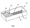
- orthopaedic kits 44 which include a case 46, a bone plate 10, a variety of bone screws 24, threaded pegs 50 of various lengths, and a drill guide 52.
- the drill guide 52 has a threaded end 54 that threads into the thread 40 of an overlapping hole 22.
- the drill guide 52 has a main drill guide surface 56 to securely hold the drill guide in a desired orientation with respect to the bone plate 10 in order to stabilize a drill (not shown) used in an orthopaedic procedure.
- an alternate embodiment of the bone plate 10' is provided with lower recesses 60 of rectangular form, extending transversely across the bone plate. These recesses 60 are preferably positioned at regular intervals along the longitudinal axis, between threaded apertures 62. Such recesses 60 are provided in order to reduce the contact area between the bottom side 14 of the bone plate 10' and the bone, as well as to prevent bending of the bone plate across a threaded aperture 62 (thus preventing warping of the threads 36). The total area removed from the bottom side 14 due to the recesses 60 is preferably less than or equal to 25% of the total surface area of the bottom side.
- the recesses 60 are substantially located exclusively on the bottom side 14 and are sized so as to define a cross-section 64 transverse to the longitudinal axis and across the recesses. This ensures that a yield strength in bending across the recesses 60 is less than across a threaded aperture 62 and thus, prevents damage of the threads upon forming of the bone plate to mate with a curvilinear surface of a bone.
- FIGs. 10a -10c a second alternate embodiment of the bone plate 10" is shown having another form of lower recesses 66. These recesses 66 do not extend across the bottom side 14 of the bone plate 10", but rather extend from a side 70 of the bone plate a short distance toward the centerline 12 of the bone plate, but do not traverse the centerline.
- the threaded apertures 100 used in the invention provide hole centers located at specific locations (as opposed to apertures that are formed as a slot). Use of threads centered at a specific point allows the bone screw to be fixed at a specific location at which the surgeon may judge the bone structure to be best suited to support such a bone screw. Unlike designs using a slot, the apertures 100 of the invention eliminate wander of the screw in the aperture. This further permits placement at specific locations for buttressing and/or secure fixing in neutral screw loading areas.
- locking bone pegs interface with the threaded apertures.
- the threads cut in the head of these pegs are designed so as to lock with the threaded apertures in order to better ensure rigid fixing of a fracture when using pegs having a body without threads.
- the locking feature used can be any of the known methods of locking threads by mechanical means.
- the bone plate 10 provides greater flexibility of choice to the surgeon in that a threaded peg providing secure fixing can be positioned at any interval along the bone plate, including at its extreme ends.
- the bone plate 10 provides greater flexibility of choice by providing multiple overlapping holes 22 oriented (1) along the longitudinal axis 12 of the bone plate, (2) oriented at an angle ⁇ to the longitudinal axis, and (3) staggered along the axis.
- the threaded apertures 40 of the bone plate 10 are provided with threads cut perpendicular to the top side 16 of the bone plate, as well as at an angle ⁇ to normal.
Abstract
Description
- This invention relates to devices, implants and prostheses used in orthopedic surgery, and, more particularly, to bone plates used to reinforce fractured bones and thus promote healing.
- A compressive screw system, also known as the DCS system, is a bone plate system that has been used in trauma surgery for many years. The procedures for use of this system are well documented by the AO Institute, an institute having as one of its goals, the promotion of new orthopaedic surgical procedures. This system included a bone plate having slots communicating therethrough. A land in which the slot is wider at one end defines a stepped surface adjacent the portion of the slot that extends through the bone plate. The stepped surface is generally cut with a spherical endmill, thus creating a spherical stepped surface.
- In a still further development, bone plates have been developed having individual threaded apertures and non-threaded apertures interspersed along the length of the plate. In this and other designs, the distance between holes has become a standard. Although an improvement over the inserts noted above, the locking positions are pre-defined, and only available in limited locations, which also reduce surgical flexibility. In another product variation, expandable, lockable inserts enter into the slots of a standard bone plate. When the bone screw passes through one of these inserts and is torqued down, the insert expands and locks the screw in place. However, this insert is locked in a secondary operation. This is not desirable because this requires more operating room time and adds complexity to the procedure. Further, the inserts must be added in the specific location before the plate is fixed to the bone and cannot be subsequently inserted. This limits the choice of placement during surgery if the need arises.
- Also, the above insert design relies on a friction lock via contact between two surfaces. Friction locks are not reliable and come lose more easily than threaded locked holes. The result of such a design is inferior to that of the threaded plate and screw designs discussed below.
- In
US Patent 5,002,544 to Klaue et al , there is shown an osteosynthetic pressure plate having a cross-section transverse to the longitudinal axis of the plate at at least one point being wider toward the upper surface than toward the lower surface and the plate having recesses in the lower surface so that upon application to a bone there is space between the bone and the plate. The cross-section between the screw holes is reduced, preferably to the extent that the resistance of the plate to bending in this area is less than in the area of the holes. Because of the reduced bend resistance between the holes, the plate can more easily be adapted to conform to the anatomy of the bone. Furthermore, this can be done without deformation of the holes, thus minimizing the resulting loss of fatigue strength and minimizing the misfit of the screw heads. - Further,
US Patent No. 5,709,686 to Takos et al describes a bone plate that has recesses or reduced thickness portions on its sides, between threaded apertures. Although the purpose is not specifically described, these recesses appear to function to avoid warpage of the threaded portions when the bone plate is bent. However, when such a bone plate is fixed to a bone, these discontinuous recesses are exposed and may potentially come into contact with and potentially aggrevate muscle tissue. - Still further,
US Patent No. 5,733,287 to Tepic et al shows (infigure 4 ), a plate that has transverse cuts 13 and alongitudinal cut 14 on the lower surface 7 to reduce contact between the plate and bone. Due to the transverse undercuts 13, the cross-section 15 between the holes is already significantly reduced and therefore is not further decreased by anadditional groove 10 on the upper surface 6 as in the embodiment according tofigure 3 . To avoid a cross-section that is too thin, thegroove 10 on the upper surface 6 is made discontinuous in shortsegmental grooves 16 providing a smooth transition into and out of the holes 8. - In yet another solution,
PCT application no. WO01/54601 - Further, this combi-hole includes two distinct overlapping portions in a single slot. One portion of the slot is suited to receive a standard bone screw, while the other portion of the slot is suited to receive a threaded peg oriented perpendicular to the top surface of the bone plate. Also, the combi-holes are generally oriented with the threaded portions being on the innermost end of the combination and the unthreaded portions oriented toward the ends of the bone plate. This improvement increased the flexibility of choice available to orthopaedic surgeons using the device in that it was more likely that a hole would be present at a suitable anchoring point in the bone plate. Nevertheless, there are often trauma situations that are best served by the threaded portion being at the extreme ends of the bone plate and/or at various positions throughout the plate. In addition, sometimes there is no specific center of the facture -in such a situation, use of the combi-hole design is limited.
- While patent application no.
WO01/54601 - In a further development, the AO Institute has studied and proposed the use of endpegs which are rigidly fixed in the extreme ends of the bone plate. Such an arrangement has been shown to better resist the flexing of the bone than use of a bone screw alone. Flexing can otherwise loosen the connection between the bone plate and bone in other bone plate systems.
- In another development, German patent
DE 4341980 A1, published on June 14, 1995 , describes a bone plate 2 having an elongated slot 8 in which the sidewalls of the long sides of the slot are not parallel and are further provided with an internal thread 9. Correspondingbone screws 3 or inserts 6 have a head 5 with an external taper 4 and thus can be fixed into any point along the length, but to various depths of penetration. Therefore, the final configuration upon fixing is indeterminate and, due to the small amount of contact between the threads of the insert or screw and the slot, as well as the fact that the screw will be able to slide in one direction, the design does not appear to lend itself to reliable fixing. -
US Patent No. 5,324,290 shows a complex bone plate having slots with countersunk circular recessed cut at intervals along the slot (a similar arrangement is shown inUS Patent No. 4,696,290 ). It further shows the bone plate torqued against the bone so as to at least marginally, conform to the shape of the bone (seeFig. 2 ). Other patents of interest includeUS Patent No. 3,716,050 ,3,659,595 ,5,681,311 ,5,261,910 , and5,364,399 , all showing combinations of conventional slots and recesses which do not fully accommodate a bone screw having a threaded head. - In comparison with the combi-hole design and the friction locking design described above, what is needed is a bone plate that provides greater flexibility of choice to the surgeon. More specifically, what is needed is a bone plate that provides this choice of plate placement while reliably and permanently fixing the bone plate to the bone fragments, in any hole position.
- What is needed is a bone plate that provides greater flexibility of choice to the surgeon, in a bone plate that has multiple orientations for the locking screw and thus, plate placement, while reliably and permanently fixing the bone plate to the bone fragments, in any hole position.
- In addition, what is needed is a versatile bone plate having recesses which determine where the bone plate will bend, in order to avoid the threads in any holes to be bent or warped, while maintaining a smooth external surface.
- Finally, what is needed is a bone plate with holes that create bi-directional compression.
- A bone plate is provided having a longitudinal axis, a bone-contacting bottom side and a top side. Sets of overlapping holes communicate through the plate from the top to the bottom side. The overlapping holes have multifaceted surfaces such as a threaded surface or a coaxial series of annular grooves. The sets of overlapping holes are adapted to receive a bone screw with a head and a bone-engaging thread.
- An object of the invention is to provide an orthopaedic surgeon greater flexibity of choice in that a threaded peg providing secure fixing can be positioned at any interval along the bone plate, including at its extreme ends.
-
-
FIG. 1a is a perspective view of a bone plate in which the overlapping holes align along a longitudinal axis of the bone plate. -
FIG. 1b is a top plan view of a bone plate in which the overlapping holes align along a longitudinal axis of the bone plate. -
FIG. 1c is a longitudinal cross-sectional view of a bone plate in which the overlapping holes align along a longitudinal axis of the bone plate. -
FIG. 1d is a top plan view of a single set of overlapping holes. -
FIG. 2a is a perspective view of a set of two overlapping holes having a threaded surface. -
FIG. 2b is a perspective view of a set of two overlapping holes in which the surface of each hole is a coaxial series of annular grooves. -
FIG. 3 is a longitudinal cross-sectional view in which some of the overlapping holes are formed normal to the top side of the plate. -
FIG. 4 is a longitudinal cross-sectional view in which all the overlapping holes are formed at an angle offset from normal to the top side of the plate. -
FIG. 5 is a top plan view of a bone plate in which the overlapping holes are staggered along a longitudinal axis of the bone plate. -
FIG. 6a is a top plan view of the bone plate showing a set of three overlapping holes. -
FIG. 6b is a longitudinal cross-sectional view showing the sets of three overlapping holes in which all holes are aligned normal to the top surface of the bone plate. -
FIG. 6c is a longitudinal cross-sectional view showing the sets of three overlapping holes in which some of the holes are aligned normal to the top surface of the bone plate. -
FIG. 6d is a longitudinal cross-sectional view showing the sets of three overlapping holes in which all holes are aligned at an angle offset from normal to the top surface of the bone plate. -
FIG. 7a is a plan view of an orthopaedic kit of the invention including a case, a bone plate, a variety of bone screws, and threaded pegs of various lengths. -
FIG. 7b is a perspective view of an orthopaedic kit of the invention including a case, a bone plate, a variety of bone screws, and a drill guide. -
FIG. 8 is a side view of a bone screw having a head and a bone-engaging thread. -
FIG. 9a is a perspective view of an alternate embodiment of the bone plate having lower recesses. -
FIG. 9b is a second perspective view of the alternate embodiment of the bone plate. -
FIG. 9c is a side view of the alternate embodiment of the bone plate. -
FIG. 10a is a perspective view of a second alternate embodiment showing lower recesses on the bone plate. -
FIG. 10b is a bottom view of the alternate embodiment of the bone plate. -
FIG. 10c is a side view of the alternate embodiment of the bone plate. - Referring now to
FIGS. 1a to 1d , abone plate 10 with alongitudinal axis 12 has a bone-contactingbottom side 14 and atop side 16. Multiple sets 20 of overlappingholes 22 communicate through theplate 10 from thetop side 16 to thebottom side 14. The overlapping holes 22 are adapted to receive abone screw 24 with ahead 26 having athread 30 and, on anopposite end 32, a body having a bone-engaging thread 34 (shown inFIG. 8 ). - The multiple sets 20 of overlapping
holes 22 allow for further adjustability and flexibility in positioning of thebone plate 10 during surgery. The overlapping holes 22 are formed normal to thetop side 16 of the plate 10 (shown inFIGS. 1c and1d ). - Referring now to
FIG. 2a and 2b , the overlappingholes 22 havemultifaceted surfaces 36. In one embodiment, themultifaceted surface 36 is a threaded surface 40 (shown inFIG. 2a ). In another embodiment, themulti-faceted surface 36 is a coaxial series of annular grooves 42 (shown inFIG. 2b ). - Overlapping
holes 22 are formed individually at an angle 0 offset from normal to thetop side 16 of theplate 10. Such allows further flexibility of choice to the surgeon as to where and how to fasten thebone plate 10. Referring again toFIGS. 1c and1d , where these overlappingholes 22 are oriented perpendicularly to thetop side 16 of thebone plate 10, he may chose to fasten the plates in a conventional manner, namely, perpendicular to the top side of the plate. - Referring now to
FIG. 3 , in a preferred embodiment, some of the overlapping holes 22 are formed normal to thetop side 16 of theplate 10. - Alternatively, as shown in
FIG. 4 , all of the overlapping holes 22 are formed at an angle 0 offset from normal to thetop side 16 of theplate 10. - Referring now to
FIG. 5 , the overlappingholes 22 may be formed offset from thelongitudinal axis 12 of thebone plate 10, in a staggered manner. - Referring now to
FIGS. 6a to 6d , in an alternate embodiment, thebone plate 10 may includesets 20 of three overlappingholes 22. Referring in particular toFIGS. 6b , where these overlappingholes 22 are oriented perpendicularly to thetop side 16 of thebone plate 10, the surgeon may chose to fasten the plates in a conventional manner. - Referring in particular to
FIG. 6c , in a preferred embodiment, some of the overlapping holes 22 are formed normal to thetop side 16 of theplate 10. - Alternatively, as shown in
FIG. 6d , all of the overlapping holes 22 are formed at an angle Ø offset from normal to thetop side 16 of theplate 10. - Referring now to
FIGs. 7a and7b , in another embodiment,orthopaedic kits 44 are provided which include acase 46, abone plate 10, a variety of bone screws 24, threaded pegs 50 of various lengths, and adrill guide 52. Thedrill guide 52 has a threaded end 54 that threads into thethread 40 of an overlappinghole 22. Thedrill guide 52 has a main drill guide surface 56 to securely hold the drill guide in a desired orientation with respect to thebone plate 10 in order to stabilize a drill (not shown) used in an orthopaedic procedure. - Referring now to
FIGs. 9a - 9c , an alternate embodiment of the bone plate 10' is provided with lower recesses 60 of rectangular form, extending transversely across the bone plate. These recesses 60 are preferably positioned at regular intervals along the longitudinal axis, between threadedapertures 62. Such recesses 60 are provided in order to reduce the contact area between thebottom side 14 of the bone plate 10' and the bone, as well as to prevent bending of the bone plate across a threaded aperture 62 (thus preventing warping of the threads 36). The total area removed from thebottom side 14 due to the recesses 60 is preferably less than or equal to 25% of the total surface area of the bottom side. - The recesses 60 are substantially located exclusively on the
bottom side 14 and are sized so as to define a cross-section 64 transverse to the longitudinal axis and across the recesses. This ensures that a yield strength in bending across the recesses 60 is less than across a threadedaperture 62 and thus, prevents damage of the threads upon forming of the bone plate to mate with a curvilinear surface of a bone. - Referring now to
FIGs. 10a -10c , a second alternate embodiment of thebone plate 10" is shown having another form oflower recesses 66. Theserecesses 66 do not extend across thebottom side 14 of thebone plate 10", but rather extend from aside 70 of the bone plate a short distance toward thecenterline 12 of the bone plate, but do not traverse the centerline. - Note that the threaded apertures 100 used in the invention provide hole centers located at specific locations (as opposed to apertures that are formed as a slot). Use of threads centered at a specific point allows the bone screw to be fixed at a specific location at which the surgeon may judge the bone structure to be best suited to support such a bone screw. Unlike designs using a slot, the apertures 100 of the invention eliminate wander of the screw in the aperture. This further permits placement at specific locations for buttressing and/or secure fixing in neutral screw loading areas.
- In another feature, locking bone pegs (not shown) interface with the threaded apertures. The threads cut in the head of these pegs are designed so as to lock with the threaded apertures in order to better ensure rigid fixing of a fracture when using pegs having a body without threads. The locking feature used can be any of the known methods of locking threads by mechanical means.
- In an advantage of the invention, the
bone plate 10 provides greater flexibility of choice to the surgeon in that a threaded peg providing secure fixing can be positioned at any interval along the bone plate, including at its extreme ends. - In another advantage, the
bone plate 10 provides greater flexibility of choice by providing multiple overlappingholes 22 oriented (1) along thelongitudinal axis 12 of the bone plate, (2) oriented at an angle Ø to the longitudinal axis, and (3) staggered along the axis. - In still another advantage, the threaded
apertures 40 of thebone plate 10 are provided with threads cut perpendicular to thetop side 16 of the bone plate, as well as at an angle Ø to normal. - Multiple variations and modifications are possible in the embodiments of the invention described here. Although certain illustrative embodiments of the invention have been shown and described here, a wide range of modifications, changes, and substitutions is contemplated in the foregoing disclosure. In some instances, some features of the present invention may be employed without a corresponding use of the other features. Accordingly, it is appropriate that the foregoing description be construed broadly and understood as being given by way of illustration and example only, the scope of the invention being limited only by the appended claims.
Claims (30)
- A bone plate (10) with a longitudinal axis (12), a bone-contacting bottom side (14) and a top side (16) with at least one set (20) of overlapping holes which communicate through the plate from the top to the bottom side, the bone plate (10) characterized in that at least two adjacent overlapping holes (22) of the at least one set (20) of overlapping holes define apertures having multifaceted surfaces (36, 40, 42).
- The bone plate (10) of claim 1, wherein the overlapping multifaceted holes (22) are formed normal to the top side (16) of the plate.
- The bone plate (10) of claim 1, wherein the overlapping multifaceted holes (22) are formed at an angle (ø) offset from normal to the top side (16) of the plate.
- The bone plate (10) of claim 1, wherein at least one of the overlapping multifaceted holes (22) is formed normal to the top side (16) of the plate and at least a second of the overlapping multifaceted holes (22) is formed at an angle (ø) offset from normal to the top side (16) of the plate.
- The bone plate (10) of claim 1, wherein a multi-faceted surface (36) is a coaxial series of annular grooves (42).
- The bone plate (10) of claims 1, wherein the aperture further comprises multiple sets (20) of overlapping holes (22).
- The bone plate (10) of claim 6, wherein the multiple sets (20) of overlapping multifaceted holes (22) are aligned on the axis (12).
- The bone plate (10) of claim 6, wherein the multiple sets (20) of overlapping multifaceted holes (22) are positioned in a staggered arrangement from the longitudinal axis (12).
- The bone plate (10) of claim 1, wherein the multi-faceted surfaces (22) are threaded surfaces.
- The bone plate (10) of claim 9, wherein the overlapping multifaceted holes (22) are formed normal to the top side (16) of the plate.
- The bone plate (10) of claim 9, wherein the overlapping multifaceted holes (22) are formed at an angle (ø) offset from normal to the top side (16) of the plate.
- The bone plate (10) of claim 9, wherein at least one of the overlapping multifaceted holes (22) is formed normal to the top side (16) of the plate (10) and at least a second of the overlapping multifaceted holes (22) is formed at an angle (ø) offset from normal to the top side (16) of the plate.
- The bone plate (10) of claim 1 wherein the set (20) of overlapping multifaceted holes (22) is adapted to receive a bone screw (24) with a head (26) and a bone-engaging thread (34).
- The bone plate (10) of claim 13, wherein at least one of the overlapping multifaceted holes (22) is formed normal to the top side (16) of the plate and at least a second of the overlapping multifaceted holes (22) is formed at an angle (ø) offset from normal to the top side (16) of the plate.
- The bone plate (10) of claim 1 wherein the set (20) is comprised of two overlapping multifaceted holes (22).
- The bone plate (10) of claim 1, wherein the set (20) is comprised of three overlapping multifaceted holes (22).
- An orthopaedic kit (44) including: a. a bone plate (10) according to claim 1; and b. at least one bone screw (24) engageable with the bone plate.
- The kit (44) of claim 17, further comprising a drill guide (52) having a main drill guide surface (56) and opposite end portions, one end portion of which is securely engageable with the multi-faceted surface (40) of a hole (22) in the bone plate (10) so as to securely hold the drill guide (52) in a desired orientation with respect to the bone plate (10) for stabilizing a drill used in an orthopaedic procedure.
- The bone plate (10) of claim 1, wherein the multifaceted surfaces (36, 40, 42) are adapted to receive a bone screw (24) with a threaded head (26) and a bone engaging threaded shank (34).
- The bone plate (10) according to claim 19, wherein the overlapping multifaceted holes (22) have centers substantially aligned along the longitudinal axis (12) of the plate.
- The bone plate (10) according to claim 19, wherein the overlapping multifaceted holes (22) further having centers staggered about the longitudinal axis (12) of the plate.
- The bone plate (10) according to claim 19, wherein the bottom side (14) includes recesses (60) located between adjacent multifaceted apertures (20) which are substantially located exclusively on the bottom side (14), the recesses (60) being sized so as to define a cross-section (64) transverse to the longitudinal axis (12) and across the recesses (60) that ensures that a yield strength in bending across the recesses is less than across a multifaceted aperture (36).
- The bone plate (10) of claim 22, wherein the recesses (60) are substantially rectangular in form.
- The bone plate (10) of claim 22, wherein the recesses (60) are equally spaced along the longitudinal axis (12).
- The bone plate (10) of claim 22, wherein the total area removed from the bottom side (14) due to the recesses (60) is less than or equal to 50% of the total surface area of the bottom side.
- The bone plate (10) of claim 22, wherein the recesses (60) are transverse and extend across the width of the bone plate.
- The bone plate (10) of claim 22, wherein the recesses (60) extend from a side of the bone plate transversely toward the longitudinal axis (12) but do not cross the axis.
- The bone plate (10) of any one of the above claims, wherein the overlapping multifaceted holes (22) are formed normal to the top side (16) of the.plate.
- The bone plate (10) of any one of the above claims, wherein the overlapping multifaceted holes (22) are formed at an angle (ø) offset from normal to the top side (16) of the plate.
- The bone plate (10) of any one of the above claims, wherein at least one of the overlapping multifaceted holes (22) is formed normal to the top side (16) of the plate and at least a second of the overlapping multifaceted holes (22) is formed at an angle (ø) offset from normal to the top side (16) of the plate.
Applications Claiming Priority (2)
| Application Number | Priority Date | Filing Date | Title |
|---|---|---|---|
| US45778603P | 2003-03-26 | 2003-03-26 | |
| PCT/IB2004/000911 WO2004084701A2 (en) | 2003-03-26 | 2004-03-26 | Locking bone plate |
Publications (3)
| Publication Number | Publication Date |
|---|---|
| EP1610700A2 EP1610700A2 (en) | 2006-01-04 |
| EP1610700A4 EP1610700A4 (en) | 2006-05-17 |
| EP1610700B1 true EP1610700B1 (en) | 2010-08-04 |
Family
ID=33098247
Family Applications (1)
| Application Number | Title | Priority Date | Filing Date |
|---|---|---|---|
| EP04723661A Revoked EP1610700B1 (en) | 2003-03-26 | 2004-03-26 | Locking bone plate |
Country Status (9)
| Country | Link |
|---|---|
| US (2) | US7695472B2 (en) |
| EP (1) | EP1610700B1 (en) |
| JP (2) | JP4427056B2 (en) |
| KR (1) | KR101104660B1 (en) |
| CN (1) | CN1764418B (en) |
| AT (1) | ATE476149T1 (en) |
| BR (1) | BRPI0408769A (en) |
| DE (1) | DE602004028451D1 (en) |
| WO (1) | WO2004084701A2 (en) |
Cited By (2)
| Publication number | Priority date | Publication date | Assignee | Title |
|---|---|---|---|---|
| US8496690B2 (en) | 2009-09-18 | 2013-07-30 | Biomet C.V. | Orthopaedic surgical components |
| EP2995270A1 (en) | 2014-09-12 | 2016-03-16 | "CHM" sp. z o.o. | The set of bone plate and bone screw used to stabilize fractures |
Families Citing this family (174)
| Publication number | Priority date | Publication date | Assignee | Title |
|---|---|---|---|---|
| US7179260B2 (en) * | 2003-09-29 | 2007-02-20 | Smith & Nephew, Inc. | Bone plates and bone plate assemblies |
| US7722653B2 (en) * | 2003-03-26 | 2010-05-25 | Greatbatch Medical S.A. | Locking bone plate |
| US7905883B2 (en) * | 2003-03-26 | 2011-03-15 | Greatbatch Medical S.A. | Locking triple pelvic osteotomy plate and method of use |
| US7776076B2 (en) * | 2004-05-11 | 2010-08-17 | Synthes Usa, Llc | Bone plate |
| US7951176B2 (en) | 2003-05-30 | 2011-05-31 | Synthes Usa, Llc | Bone plate |
| CA2536960C (en) | 2003-08-26 | 2011-12-06 | Synthes Gmbh | Bone plate |
| US11259851B2 (en) | 2003-08-26 | 2022-03-01 | DePuy Synthes Products, Inc. | Bone plate |
| US8105367B2 (en) | 2003-09-29 | 2012-01-31 | Smith & Nephew, Inc. | Bone plate and bone plate assemblies including polyaxial fasteners |
| US8182485B1 (en) * | 2003-11-21 | 2012-05-22 | Toby Orthopaedics, Llc | Fracture fixation system |
| US8574268B2 (en) | 2004-01-26 | 2013-11-05 | DePuy Synthes Product, LLC | Highly-versatile variable-angle bone plate system |
| US11291484B2 (en) | 2004-01-26 | 2022-04-05 | DePuy Synthes Products, Inc. | Highly-versatile variable-angle bone plate system |
| US7846183B2 (en) | 2004-02-06 | 2010-12-07 | Spinal Elements, Inc. | Vertebral facet joint prosthesis and method of fixation |
| WO2006091827A2 (en) * | 2005-02-25 | 2006-08-31 | Regents Of The University Of California | Device and template for canine humeral slide osteotomy |
| US20080045960A1 (en) * | 2004-03-25 | 2008-02-21 | Bruecker Kenneth | Locking tpo plate and method of use |
| US9504583B2 (en) | 2004-06-10 | 2016-11-29 | Spinal Elements, Inc. | Implant and method for facet immobilization |
| US8172886B2 (en) | 2004-12-14 | 2012-05-08 | Depuy Products, Inc. | Bone plate with pre-assembled drill guide tips |
| US8197523B2 (en) * | 2005-02-15 | 2012-06-12 | Apex Biomedical Company, Llc | Bone screw for positive locking but flexible engagement to a bone |
| US8740955B2 (en) | 2005-02-15 | 2014-06-03 | Zimmer, Inc. | Bone screw with multiple thread profiles for far cortical locking and flexible engagement to a bone |
| EP1693013A1 (en) * | 2005-02-22 | 2006-08-23 | Kyon | Plate and screws for treatment of bone fractures |
| US8016887B1 (en) * | 2005-03-24 | 2011-09-13 | Cardinal Spine, Llc | Spinal implant with overlay |
| DE102005015496B4 (en) * | 2005-03-31 | 2012-11-15 | Intercus Gmbh | Osteosynthesis implant with non-intermeshing bushings for the insertion of bone screws |
| US8070749B2 (en) * | 2005-05-12 | 2011-12-06 | Stern Joseph D | Revisable anterior cervical plating system |
| CN101272743B (en) | 2005-07-25 | 2011-01-26 | 史密夫和内修有限公司 | Polyaxial fastener systems |
| US8382807B2 (en) * | 2005-07-25 | 2013-02-26 | Smith & Nephew, Inc. | Systems and methods for using polyaxial plates |
| AU2006306120B2 (en) | 2005-10-25 | 2012-11-15 | Anthem Orthopaedics Llc | Bone fastening assembly and bushing and screw for use therewith |
| US8100952B2 (en) | 2005-12-22 | 2012-01-24 | Anthem Orthopaedics Llc | Drug delivering bone plate and method and targeting device for use therewith |
| EP1800615B1 (en) | 2005-12-23 | 2007-12-12 | aap Implantate AG | Bone plate |
| US7473255B2 (en) * | 2006-02-08 | 2009-01-06 | Synthes (U.S.A.) | Transbuccal plate holding cannula |
| US7935126B2 (en) | 2006-03-20 | 2011-05-03 | Depuy Products, Inc. | Bone plate shaping system |
| KR101408732B1 (en) * | 2006-07-07 | 2014-07-02 | 스위스 프로 올소페딕 에스에이 | Bone plate with complex, adjacent holes joined by a relief-space |
| DE202006019220U1 (en) * | 2006-12-19 | 2007-05-24 | Zrinski Ag | Orthopedic screw fastening system for fixing at bone of patient, has through-holes cut on one another so that intersection line and surfaces are produced in direction of plate thickness, where line and surfaces co-operate with head windings |
| DE102007005417A1 (en) * | 2006-12-19 | 2008-06-26 | Zrinski Ag | Plate implant, in particular for use on a spinal column, with a screw closure system |
| US7759317B2 (en) * | 2006-12-28 | 2010-07-20 | Bmb Patent Holding Corporation | Analgesic and anti-inflammatory compositions and methods with flavonoid glycoside-type compounds |
| US8182511B2 (en) * | 2007-01-29 | 2012-05-22 | Polaris Biotechnology, Inc. | Craniospinal fusion method and apparatus |
| US20090036894A1 (en) * | 2007-01-29 | 2009-02-05 | Polaris Biotechnology, Inc. | Method of treating a neurological condition through correction and stabilization of the clivo-axial angle |
| US8043342B2 (en) | 2007-01-29 | 2011-10-25 | Polaris Biotechnology, Inc. | Craniospinal fusion method and apparatus |
| US8403965B2 (en) * | 2007-01-29 | 2013-03-26 | Polaris Biotechnology, Inc. | Vertebra attachment method and system |
| US9827023B2 (en) | 2007-01-29 | 2017-11-28 | Life Spine, Inc. | Craniospinal fusion method and apparatus |
| US8556939B2 (en) * | 2008-01-08 | 2013-10-15 | Fraser Cummins Henderson | Mathematical relationship of strain, neurological dysfunction and abnormal behavior resulting from neurological dysfunction of the brainstem |
| US8398690B2 (en) * | 2007-02-07 | 2013-03-19 | Apex Biomedical Company, Llc | Rotationally asymmetric bone screw |
| US8992533B2 (en) | 2007-02-22 | 2015-03-31 | Spinal Elements, Inc. | Vertebral facet joint drill and method of use |
| US8652137B2 (en) | 2007-02-22 | 2014-02-18 | Spinal Elements, Inc. | Vertebral facet joint drill and method of use |
| US9072548B2 (en) * | 2007-06-07 | 2015-07-07 | Anthem Orthopaedics Llc | Spine repair assembly |
| SG183774A1 (en) * | 2007-08-27 | 2012-09-27 | Sushrut Surgicals Pvt Ltd | Bone plates and bone plate assemblies |
| WO2009089395A2 (en) * | 2008-01-08 | 2009-07-16 | Polaris Biotechnology, Inc. | Osteointegration apparatus |
| US8267973B2 (en) | 2008-02-27 | 2012-09-18 | Shoulder Options, Inc. | Fixable suture anchor plate and method for tendon-to-bone repair |
| US20090228010A1 (en) * | 2008-03-10 | 2009-09-10 | Eduardo Gonzalez-Hernandez | Bone fixation system |
| US8728126B2 (en) * | 2008-03-10 | 2014-05-20 | Dennis L. Steffen | Bone fixation system and method |
| AU2008354730A1 (en) | 2008-04-17 | 2009-10-22 | Toby Orthopaedics, Inc. | Soft tissue attachment system and clip |
| US8257407B2 (en) * | 2008-04-23 | 2012-09-04 | Aryan Henry E | Bone plate system and method |
| US20100057086A1 (en) * | 2008-08-29 | 2010-03-04 | Zimmer, Inc. | Anodized locking plate components |
| EP2158863B1 (en) * | 2008-09-02 | 2013-12-11 | Stryker Trauma AG | Bone plate with synchronized thread |
| US10251757B2 (en) * | 2008-09-17 | 2019-04-09 | Skeletal Dynamics Llc | Grooved slot allowing adjustment of the position of a bone fixation device for osteosynthesis |
| FR2936700B1 (en) | 2008-10-02 | 2012-04-13 | Memometal Technologies | ORTHOPEDIC IMPLANT IN THE FORM OF A PLATE TO BE FIXED BETWEEN TWO BONE PARTS |
| US8486114B2 (en) | 2008-10-10 | 2013-07-16 | Acute Innovations Llc | Cerclage system for bone |
| DE102008043370A1 (en) * | 2008-10-31 | 2010-05-06 | Universität Rostock | Fixation device for bones |
| US8808292B2 (en) | 2008-11-11 | 2014-08-19 | Zimmer Gmbh | Orthopedic screw |
| US8366719B2 (en) | 2009-03-18 | 2013-02-05 | Integrated Spinal Concepts, Inc. | Image-guided minimal-step placement of screw into bone |
| JP2010233915A (en) * | 2009-03-31 | 2010-10-21 | Olympus Terumo Biomaterials Corp | Bone plate and bone plate system |
| US20100262193A1 (en) * | 2009-04-08 | 2010-10-14 | Robert Frigg | Osseosynthesis Plate with Keyhole Feature |
| EP2248479B1 (en) | 2009-05-06 | 2012-09-19 | Greatbatch Ltd. | Bone plate assembly |
| US8986353B2 (en) | 2009-07-09 | 2015-03-24 | Orthohelix Surgical Designs, Inc. | Osteotomy plate, plate driver and method for their use |
| US10390867B2 (en) | 2009-09-18 | 2019-08-27 | Biomet C.V. | Bone plate system and method |
| US8496692B2 (en) | 2009-09-21 | 2013-07-30 | Jmea Corporation | Locking securing member |
| CN102740786A (en) * | 2009-12-22 | 2012-10-17 | 托比骨科有限公司 | Bone plate and tool assembly and method for use thereof |
| CA2789011C (en) * | 2010-03-04 | 2019-06-18 | Synthes Usa, Llc | Ulna osteotomy system |
| ATE556665T1 (en) * | 2010-03-08 | 2012-05-15 | Stryker Trauma Sa | SYSTEMS DE FIXATION OSSEUSE AVEC FILS PROFILES INCURVES |
| US20110218580A1 (en) * | 2010-03-08 | 2011-09-08 | Stryker Trauma Sa | Bone fixation system with curved profile threads |
| KR101804230B1 (en) | 2010-04-20 | 2018-01-10 | 신세스 게엠바하 | Intramedullary nail aiming device |
| DE102010025001B4 (en) * | 2010-06-24 | 2016-08-04 | Aap Implantate Ag | Fixation system with bone plate and bone screw |
| DE102010025702B4 (en) * | 2010-06-30 | 2016-08-18 | Aap Implantate Ag | Fixation system for bone with bone plate and bone screws |
| US8753396B1 (en) | 2010-09-13 | 2014-06-17 | Theken Spine, Llc | Intervertebral implant having back-out prevention feature |
| WO2012042592A1 (en) * | 2010-09-28 | 2012-04-05 | オリンパステルモバイオマテリアル株式会社 | Bone plate and bone plate system |
| US8961573B2 (en) | 2010-10-05 | 2015-02-24 | Toby Orthopaedics, Inc. | System and method for facilitating repair and reattachment of comminuted bone portions |
| WO2012058448A2 (en) | 2010-10-27 | 2012-05-03 | Toby Orthopaedics, Llc | System and method for fracture replacement of comminuted bone fractures or portions thereof adjacent bone joints |
| US8709092B2 (en) | 2011-02-16 | 2014-04-29 | Genesis Medical Devices, LLC | Periprosthetic fracture management enhancements |
| USD724733S1 (en) | 2011-02-24 | 2015-03-17 | Spinal Elements, Inc. | Interbody bone implant |
| US9271765B2 (en) | 2011-02-24 | 2016-03-01 | Spinal Elements, Inc. | Vertebral facet joint fusion implant and method for fusion |
| US8740949B2 (en) | 2011-02-24 | 2014-06-03 | Spinal Elements, Inc. | Methods and apparatus for stabilizing bone |
| US9254154B2 (en) | 2011-03-03 | 2016-02-09 | Toby Orthopaedic, Inc. | Anterior lesser tuberosity fixed angle fixation device and method of use associated therewith |
| US8672978B2 (en) * | 2011-03-04 | 2014-03-18 | Zimmer Spine, Inc. | Transverse connector |
| BR112013032140A2 (en) | 2011-06-15 | 2016-12-13 | Smith & Nephew Inc | variable angle locking implant |
| TWI554242B (en) * | 2011-09-06 | 2016-10-21 | 德派信迪思公司 | Pancarpal arthrodesis bone plate |
| WO2013037387A1 (en) | 2011-09-16 | 2013-03-21 | Stryker Trauma Gmbh | Polyaxial locking hole arrangement |
| CN103040509A (en) * | 2011-10-14 | 2013-04-17 | 北京市春立正达医疗器械股份有限公司 | Y-shaped anterior bone plate |
| USD739935S1 (en) | 2011-10-26 | 2015-09-29 | Spinal Elements, Inc. | Interbody bone implant |
| US9271772B2 (en) | 2011-10-27 | 2016-03-01 | Toby Orthopaedics, Inc. | System and method for fracture replacement of comminuted bone fractures or portions thereof adjacent bone joints |
| US9730797B2 (en) | 2011-10-27 | 2017-08-15 | Toby Orthopaedics, Inc. | Bone joint replacement and repair assembly and method of repairing and replacing a bone joint |
| US9402667B2 (en) | 2011-11-09 | 2016-08-02 | Eduardo Gonzalez-Hernandez | Apparatus and method for use of the apparatus for fracture fixation of the distal humerus |
| CN104093379B (en) * | 2011-12-07 | 2017-09-08 | 史密夫和内修有限公司 | Orthopaedic implants reinforcer |
| US8632574B2 (en) * | 2011-12-07 | 2014-01-21 | Biomet C.V. | Reduced component bone plating system |
| EP2626020B1 (en) * | 2012-02-13 | 2014-04-02 | Stryker Trauma SA | Attachment device for a bone plate |
| GB2515712B (en) | 2012-04-30 | 2018-10-24 | Acute Innovations Llc | System for binding bone |
| RU2641859C2 (en) * | 2012-08-23 | 2018-01-22 | Зинтес Гмбх | System for bone fixation |
| US9452005B2 (en) | 2012-08-23 | 2016-09-27 | DePuy Synthes Products, Inc. | Bone fixation system |
| US10004603B2 (en) | 2012-08-23 | 2018-06-26 | DePuy Synthes Products, Inc. | Bone implant |
| US9101426B2 (en) | 2012-10-11 | 2015-08-11 | Stryker Trauma Sa | Cable plug |
| US9283008B2 (en) | 2012-12-17 | 2016-03-15 | Toby Orthopaedics, Inc. | Bone plate for plate osteosynthesis and method for use thereof |
| US9820784B2 (en) | 2013-03-14 | 2017-11-21 | Spinal Elements, Inc. | Apparatus for spinal fixation and methods of use |
| US20140277181A1 (en) * | 2013-03-14 | 2014-09-18 | Arthrex, Inc. | Variable angle locking screw and plate |
| US9421044B2 (en) | 2013-03-14 | 2016-08-23 | Spinal Elements, Inc. | Apparatus for bone stabilization and distraction and methods of use |
| US9433454B2 (en) | 2013-03-14 | 2016-09-06 | Amei Technologies, Inc. | Variable angle screws, plates and systems |
| USD765853S1 (en) * | 2013-03-14 | 2016-09-06 | Spinal Elements, Inc. | Flexible elongate member with a portion configured to receive a bone anchor |
| US9333014B2 (en) | 2013-03-15 | 2016-05-10 | Eduardo Gonzalez-Hernandez | Bone fixation and reduction apparatus and method for fixation and reduction of a distal bone fracture and malunion |
| KR101471627B1 (en) * | 2013-04-02 | 2014-12-11 | 주식회사 제일메디칼코퍼레이션 | Locking angle adjustable bone plate system |
| US9811830B2 (en) | 2013-07-03 | 2017-11-07 | Google Inc. | Method, medium, and system for online fraud prevention based on user physical location data |
| US20150039038A1 (en) | 2013-08-05 | 2015-02-05 | Stephan Eckhof | Orthopedic Screw Fastener System Including Locking and Non-Locking Screws |
| US9510880B2 (en) | 2013-08-13 | 2016-12-06 | Zimmer, Inc. | Polyaxial locking mechanism |
| US9468479B2 (en) | 2013-09-06 | 2016-10-18 | Cardinal Health 247, Inc. | Bone plate |
| US9456855B2 (en) | 2013-09-27 | 2016-10-04 | Spinal Elements, Inc. | Method of placing an implant between bone portions |
| US9839450B2 (en) | 2013-09-27 | 2017-12-12 | Spinal Elements, Inc. | Device and method for reinforcement of a facet |
| US9855083B2 (en) * | 2013-12-12 | 2018-01-02 | Extremity Designs, Llc | Bone plate with elevated suture hole structures |
| US10226287B2 (en) | 2014-03-31 | 2019-03-12 | Association For The Advancement Of Musculoskeletal | Bone plate with versatile screw holes |
| EP2932927B1 (en) * | 2014-04-17 | 2017-09-20 | Biedermann Technologies GmbH & Co. KG | Bone plate with enlarged angle of inclination for a bone anchor to a favored side |
| CN105078557A (en) * | 2014-05-14 | 2015-11-25 | 常州市康辉医疗器械有限公司 | Locking and compressing hole and application thereof |
| US10499968B2 (en) | 2014-08-08 | 2019-12-10 | Stryker European Holdings I, Llc | Cable plugs for bone plates |
| US20160045238A1 (en) * | 2014-08-13 | 2016-02-18 | Biomet C.V. | Calcaneal bone plate targeting guide |
| US11478275B2 (en) | 2014-09-17 | 2022-10-25 | Spinal Elements, Inc. | Flexible fastening band connector |
| CN105640627B (en) * | 2014-11-13 | 2018-03-20 | 义守大学 | Exter-nal fixer and its adjustment component |
| US9987051B2 (en) | 2015-01-27 | 2018-06-05 | K2M, Inc. | Interbody spacer |
| US10028841B2 (en) | 2015-01-27 | 2018-07-24 | K2M, Inc. | Interbody spacer |
| JP2018502693A (en) | 2015-01-27 | 2018-02-01 | スパイナル・エレメンツ・インコーポレーテッド | Facet joint implant |
| CN104739496A (en) * | 2015-03-12 | 2015-07-01 | 创辉医疗器械江苏有限公司 | Fine-thread universal bone fracture plate |
| WO2016172536A1 (en) * | 2015-04-24 | 2016-10-27 | Biomet Manufacturing, Llc | Clavicle implants |
| US11076898B2 (en) | 2015-08-27 | 2021-08-03 | Globus Medical, Inc. | Proximal humeral stabilization system |
| US11197682B2 (en) | 2015-08-27 | 2021-12-14 | Globus Medical, Inc. | Proximal humeral stabilization system |
| US10687874B2 (en) | 2015-08-27 | 2020-06-23 | Globus Medical, Inc | Proximal humeral stabilization system |
| GB2557840B (en) | 2015-09-18 | 2021-07-21 | Smith & Nephew Inc | Bone plate |
| US10130402B2 (en) | 2015-09-25 | 2018-11-20 | Globus Medical, Inc. | Bone fixation devices having a locking feature |
| US9974581B2 (en) | 2015-11-20 | 2018-05-22 | Globus Medical, Inc. | Expandable intramedullary systems and methods of using the same |
| WO2017096098A1 (en) * | 2015-12-01 | 2017-06-08 | Revivo Medical, Llc | Bone fixation apparatus with fastener securement mechanism and methods of use |
| JP6082501B1 (en) * | 2016-02-08 | 2017-02-15 | 株式会社コバヤシ精密工業 | Bone plate and bone plate system |
| US9795411B2 (en) | 2016-03-02 | 2017-10-24 | Globus Medical, Inc. | Fixators for bone stabilization and associated systems and methods |
| CN105662567A (en) * | 2016-03-16 | 2016-06-15 | 苏州瑞华医院有限公司 | Bone plate provided with grooves |
| US10531905B2 (en) | 2016-04-19 | 2020-01-14 | Globus Medical, Inc. | Implantable compression screws |
| EP3257458A1 (en) * | 2016-06-17 | 2017-12-20 | ORTHOFIX S.r.l. | Bone plate for epiphysiodesis |
| US10383668B2 (en) | 2016-08-17 | 2019-08-20 | Globus Medical, Inc. | Volar distal radius stabilization system |
| US11141204B2 (en) | 2016-08-17 | 2021-10-12 | Globus Medical Inc. | Wrist stabilization systems |
| US11213327B2 (en) | 2016-08-17 | 2022-01-04 | Globus Medical, Inc. | Fracture plates, systems, and methods |
| US10575884B2 (en) | 2016-08-17 | 2020-03-03 | Globus Medical, Inc. | Fracture plates, systems, and methods |
| US10420596B2 (en) | 2016-08-17 | 2019-09-24 | Globus Medical, Inc. | Volar distal radius stabilization system |
| US10687873B2 (en) | 2016-08-17 | 2020-06-23 | Globus Medical Inc. | Stabilization systems |
| US11432857B2 (en) | 2016-08-17 | 2022-09-06 | Globus Medical, Inc. | Stabilization systems |
| US11197701B2 (en) | 2016-08-17 | 2021-12-14 | Globus Medical, Inc. | Stabilization systems |
| US11331128B2 (en) | 2016-08-17 | 2022-05-17 | Globus Medical Inc. | Distal radius stabilization system |
| US10751098B2 (en) | 2016-08-17 | 2020-08-25 | Globus Medical Inc. | Stabilization systems |
| US10624686B2 (en) | 2016-09-08 | 2020-04-21 | DePuy Synthes Products, Inc. | Variable angel bone plate |
| US10820930B2 (en) | 2016-09-08 | 2020-11-03 | DePuy Synthes Products, Inc. | Variable angle bone plate |
| US10905476B2 (en) | 2016-09-08 | 2021-02-02 | DePuy Synthes Products, Inc. | Variable angle bone plate |
| US10881438B2 (en) | 2017-03-10 | 2021-01-05 | Globus Medical, Inc. | Clavicle fixation system |
| US10905477B2 (en) | 2017-03-13 | 2021-02-02 | Globus Medical, Inc. | Bone stabilization systems |
| US10368928B2 (en) | 2017-03-13 | 2019-08-06 | Globus Medical, Inc. | Bone stabilization systems |
| US10856920B2 (en) | 2017-09-13 | 2020-12-08 | Globus Medical Inc. | Bone stabilization systems |
| US11096730B2 (en) | 2017-09-13 | 2021-08-24 | Globus Medical Inc. | Bone stabilization systems |
| US11071570B2 (en) | 2018-03-02 | 2021-07-27 | Globus Medical, Inc. | Distal tibial plating system |
| US11224468B2 (en) | 2018-03-02 | 2022-01-18 | Globus Medical, Inc. | Distal tibial plating system |
| US11039865B2 (en) | 2018-03-02 | 2021-06-22 | Stryker European Operations Limited | Bone plates and associated screws |
| US11026727B2 (en) | 2018-03-20 | 2021-06-08 | DePuy Synthes Products, Inc. | Bone plate with form-fitting variable-angle locking hole |
| US10772665B2 (en) * | 2018-03-29 | 2020-09-15 | DePuy Synthes Products, Inc. | Locking structures for affixing bone anchors to a bone plate, and related systems and methods |
| US11141172B2 (en) | 2018-04-11 | 2021-10-12 | Globus Medical, Inc. | Method and apparatus for locking a drill guide in a polyaxial hole |
| US11013541B2 (en) | 2018-04-30 | 2021-05-25 | DePuy Synthes Products, Inc. | Threaded locking structures for affixing bone anchors to a bone plate, and related systems and methods |
| US10828076B2 (en) | 2018-05-17 | 2020-11-10 | Biedermann Technologies Gmbh & Co. Kg | Bone fixation assembly with enlarged angle of inclination for a bone anchor to a favored side |
| USD874650S1 (en) | 2018-10-23 | 2020-02-04 | DePuy Synthes Products, Inc. | Distal femur plate |
| US10925651B2 (en) | 2018-12-21 | 2021-02-23 | DePuy Synthes Products, Inc. | Implant having locking holes with collection cavity for shavings |
| US11202663B2 (en) | 2019-02-13 | 2021-12-21 | Globus Medical, Inc. | Proximal humeral stabilization systems and methods thereof |
| JP2022535698A (en) | 2019-05-22 | 2022-08-10 | スパイナル・エレメンツ・インコーポレーテッド | Bone ties and bone tie inserters |
| US11457959B2 (en) | 2019-05-22 | 2022-10-04 | Spinal Elements, Inc. | Bone tie and bone tie inserter |
| US11129627B2 (en) | 2019-10-30 | 2021-09-28 | Globus Medical, Inc. | Method and apparatus for inserting a bone plate |
| US11723647B2 (en) | 2019-12-17 | 2023-08-15 | Globus Medical, Inc. | Syndesmosis fixation assembly |
| US11304733B2 (en) | 2020-02-14 | 2022-04-19 | Spinal Elements, Inc. | Bone tie methods |
| US11851947B2 (en) * | 2020-04-03 | 2023-12-26 | Cornellcookson, Llc | Universal endlock |
| CN116133605A (en) | 2020-05-29 | 2023-05-16 | 史赛克欧洲运营有限公司 | Funnel hole for intramedullary nail |
| US11950814B2 (en) | 2022-01-04 | 2024-04-09 | Extremity Medical, Llc | Orthopedic plate with locking compression slot |
| US20230240671A1 (en) * | 2022-01-31 | 2023-08-03 | Nuvasive, Inc. | Surgical retraction system |
Family Cites Families (109)
| Publication number | Priority date | Publication date | Assignee | Title |
|---|---|---|---|---|
| DE207884C (en) | ||||
| US2699774A (en) | 1952-05-12 | 1955-01-18 | Livingston Herman Harrison | Bone pin locking device |
| CH462375A (en) | 1966-06-22 | 1968-09-15 | Synthes Ag | Osteosynthetic pressure plate |
| US3659595A (en) | 1969-10-22 | 1972-05-02 | Edward J Haboush | Compensating plates for bone fractures |
| US3716050A (en) | 1971-02-11 | 1973-02-13 | F Johnston | Olecranon plate |
| US3779240A (en) * | 1972-03-31 | 1973-12-18 | S Kondo | Compression plate for osteosynthesis |
| US3824995A (en) | 1972-07-24 | 1974-07-23 | Villiers E | Trochanteric plate |
| US3842825A (en) | 1973-11-12 | 1974-10-22 | R Wagner | Hip fixation device |
| US4120298A (en) | 1976-12-06 | 1978-10-17 | Fixel Irving E | Implant to secure the greater trochanter |
| CH611147A5 (en) * | 1977-01-07 | 1979-05-31 | Mueller Kurt | Osteosynthesis compression plate |
| CH613858A5 (en) | 1977-04-22 | 1979-10-31 | Straumann Inst Ag | |
| FR2472373A1 (en) | 1979-12-24 | 1981-07-03 | Tornier Sa | Epiphysis plate for osteosynthesis - has horizontal arm accommodating obliquely inserted screws |
| CH645013A5 (en) * | 1980-04-14 | 1984-09-14 | Wenk Wilh Ag | Osteosynthetic COMPRESSION PLATE. |
| US4403606A (en) | 1980-05-09 | 1983-09-13 | The Regents Of The University Of California | Compatible internal bone fixation plate |
| CH651192A5 (en) * | 1980-11-20 | 1985-09-13 | Synthes Ag | OSTEOSYNTHETIC DEVICE AND CORRESPONDING DRILL GAUGE. |
| US4409973A (en) | 1981-01-29 | 1983-10-18 | Neufeld John A | Method and apparatus for corrective osteotomy |
| CH650915A5 (en) | 1981-03-16 | 1985-08-30 | Synthes Ag | DEVICE FOR STABILIZING THE AREA OF A BONE BREAK OR OSTEOTOMY. |
| IE52844B1 (en) | 1981-05-13 | 1988-03-16 | Fort Vale Eng Ltd | An improved manlid for a container tank |
| US4502474A (en) | 1981-08-20 | 1985-03-05 | Comparetto John E | Bone wedge guidance system |
| US4501268A (en) | 1981-08-20 | 1985-02-26 | Comparetto John E | Bone wedge guidance system |
| US4421112A (en) | 1982-05-20 | 1983-12-20 | Minnesota Mining And Manufacturing Company | Tibial osteotomy guide assembly and method |
| US4454876A (en) | 1982-05-25 | 1984-06-19 | University Of Pittsburgh | Pelvic fixation plate and method of implanting same |
| FR2530453B1 (en) | 1982-07-26 | 1985-01-11 | Inst Nat Sante Rech Med | OSTEOSYNTHESIS PLATES FOR BONE DEROTATION |
| AT378324B (en) | 1982-09-13 | 1985-07-25 | Streli Elke | TINNED PLATE FOR FIXING THE BONES IN THE BODIES IN BONE BREAKS |
| US4509511A (en) | 1983-06-30 | 1985-04-09 | Neufeld John A | Method and apparatus for corrective osteotomy |
| US4662891A (en) | 1983-11-21 | 1987-05-05 | Joint Medical Products Corporation | Fixation elements for artificial joints |
| US4696290A (en) | 1983-12-16 | 1987-09-29 | Acromed Corporation | Apparatus for straightening spinal columns |
| US4611581A (en) * | 1983-12-16 | 1986-09-16 | Acromed Corporation | Apparatus for straightening spinal columns |
| FR2556583B1 (en) | 1983-12-19 | 1986-04-18 | Inst Nat Sante Rech Med | OSTEOSYNTHESIS PLATES FOR BONE DEROTATION, ESPECIALLY FEMORAL DEROTATION |
| US4565191A (en) | 1984-01-12 | 1986-01-21 | Slocum D Barclay | Apparatus and method for performing cuneiform osteotomy |
| US4545876A (en) | 1984-05-02 | 1985-10-08 | United Technologies Corporation | Method and apparatus for surface treating |
| DE8431616U1 (en) | 1984-10-27 | 1984-12-20 | Howmedica International, Inc. Zweigniederlassung Kiel, 2314 Schönkirchen | Plate for osteosynthesis |
| DE3442004C1 (en) * | 1984-11-16 | 1986-04-24 | Otte, Heinz, Dr.med., 8712 Volkach | Bone fixation apparatus for the treatment of fractures |
| CH666176A5 (en) | 1984-11-30 | 1988-07-15 | Straumann Inst Ag | DEVICE FOR TREATING A BONE AND NAIL FOR SUCH A DEVICE. |
| DE8513288U1 (en) * | 1985-05-06 | 1986-09-04 | Wolter, Dietmar, Prof. Dr., 2000 Hamburg | Osteosynthesis plate |
| US4677973A (en) | 1985-05-28 | 1987-07-07 | Barclay Slocum | Proximal, tibial osteotomy for leveling a tibial plateau |
| PL147580B1 (en) | 1986-04-14 | 1989-06-30 | Plate for uniting epiphysis and diaphysis of broken bone | |
| AT387711B (en) | 1986-07-15 | 1989-03-10 | David Thomas | BONE FIXATION PLATE |
| FR2606268B1 (en) | 1986-11-07 | 1989-02-03 | Landos Applic Orthopediques Fs | DEVICE FOR FEMALE NECK OSTEOSYNTHESIS |
| US4762122A (en) | 1987-02-06 | 1988-08-09 | Barclay Slocum | Device and method for pelvic osteotomy fixation |
| US5216941A (en) | 1987-05-27 | 1993-06-08 | Harald Kolvereid | Tool for securing a fastening device |
| US5232249A (en) | 1987-05-27 | 1993-08-03 | Harald Kolvereid | Fastening device |
| US4790297A (en) | 1987-07-24 | 1988-12-13 | Biotechnology, Inc. | Spinal fixation method and system |
| EP0355035B1 (en) | 1987-11-03 | 1994-05-18 | SYNTHES AG, Chur | Bone plate with conical holes |
| CH673762A5 (en) * | 1987-12-02 | 1990-04-12 | Synthes Ag | |
| DE8808123U1 (en) | 1988-06-24 | 1988-09-22 | Herzberg, Wolfgang, Dr. Med., 2000 Wedel, De | |
| US4957479A (en) | 1988-10-17 | 1990-09-18 | Vance Products Incorporated | Indwelling ureteral stent placement apparatus |
| DE3838774A1 (en) | 1988-11-11 | 1990-05-17 | Mecron Med Prod Gmbh | SLIDING PLATE |
| US4959065A (en) | 1989-07-14 | 1990-09-25 | Techmedica, Inc. | Bone plate with positioning member |
| DE3923995A1 (en) * | 1989-07-20 | 1991-01-31 | Lutz Biedermann | BONE STABILIZING ELEMENT |
| US5087260A (en) | 1989-09-15 | 1992-02-11 | Fixel Irving E | Total femoral hip system |
| US5006120A (en) | 1989-10-10 | 1991-04-09 | Carter Peter R | Distal radial fracture set and method for repairing distal radial fractures |
| US5015248A (en) | 1990-06-11 | 1991-05-14 | New York Society For The Relief Of The Ruptured & Crippled, Maintaining The Hospital For Special Surgery | Bone fracture fixation device |
| US5085660A (en) | 1990-11-19 | 1992-02-04 | Lin Kwan C | Innovative locking plate system |
| PT100685A (en) * | 1991-07-15 | 1994-05-31 | Danek Group Inc | SPINAL FIXING SYSTEM |
| US5275601A (en) | 1991-09-03 | 1994-01-04 | Synthes (U.S.A) | Self-locking resorbable screws and plates for internal fixation of bone fractures and tendon-to-bone attachment |
| US5176679A (en) | 1991-09-23 | 1993-01-05 | Lin Chih I | Vertebral locking and retrieving system |
| US5304180A (en) | 1992-01-17 | 1994-04-19 | Slocum D Barclay | Tibial osteotomy fixation plate |
| US5261910A (en) | 1992-02-19 | 1993-11-16 | Acromed Corporation | Apparatus for maintaining spinal elements in a desired spatial relationship |
| US5324290A (en) | 1992-09-24 | 1994-06-28 | Danek Medical, Inc. | Anterior thoracolumbar plate |
| JPH0748247Y2 (en) * | 1992-11-16 | 1995-11-08 | 株式会社タグチ | Bone joint |
| DE59308616D1 (en) | 1993-01-25 | 1998-07-02 | Synthes Ag | COUNTER-TENSION DISC FOR PLATE OSTOSYNTHESIS |
| US5364399A (en) * | 1993-02-05 | 1994-11-15 | Danek Medical, Inc. | Anterior cervical plating system |
| US6066175A (en) * | 1993-02-16 | 2000-05-23 | Henderson; Fraser C. | Fusion stabilization chamber |
| DE4341980B4 (en) | 1993-12-09 | 2005-02-17 | Königsee Implantate und Instrumente zur Ostheosynthese GmbH | Osteosynthetic bone plate |
| DE4343117C2 (en) | 1993-12-17 | 1999-11-04 | Dietmar Wolter | Bone fixation system |
| CA2144353C (en) * | 1994-05-24 | 2001-08-21 | Slobodan Tepic | Bone plate |
| DE4438264C2 (en) * | 1994-09-08 | 1996-11-28 | Schaefer Micomed Gmbh | Osteosynthesis device |
| US5810823A (en) | 1994-09-12 | 1998-09-22 | Synthes (U.S.A.) | Osteosynthetic bone plate and lock washer |
| US5681311A (en) | 1994-09-15 | 1997-10-28 | Smith & Nephew, Inc. | Osteosynthesis apparatus |
| US5601553A (en) * | 1994-10-03 | 1997-02-11 | Synthes (U.S.A.) | Locking plate and bone screw |
| US5976141A (en) | 1995-02-23 | 1999-11-02 | Synthes (U.S.A.) | Threaded insert for bone plate screw hole |
| US5709686A (en) | 1995-03-27 | 1998-01-20 | Synthes (U.S.A.) | Bone plate |
| ES2158127T3 (en) | 1995-09-06 | 2001-09-01 | Synthes Ag | OSEA SHEET. |
| US5899906A (en) | 1996-01-18 | 1999-05-04 | Synthes (U.S.A.) | Threaded washer |
| US5868749A (en) | 1996-04-05 | 1999-02-09 | Reed; Thomas M. | Fixation devices |
| FR2748387B1 (en) * | 1996-05-13 | 1998-10-30 | Stryker France Sa | BONE FIXATION DEVICE, IN PARTICULAR TO THE SACRUM, IN OSTEOSYNTHESIS OF THE SPINE |
| CA2262441C (en) | 1996-08-12 | 2004-12-28 | Synthes (U.S.A.) | Bone plate |
| CA2523814C (en) * | 1997-02-11 | 2007-02-06 | Gary Karlin Michelson | Segmentable skeletal plating system |
| IES77331B2 (en) * | 1997-06-03 | 1997-12-03 | Tecos Holdings Inc | Pluridirectional and modulable vertebral osteosynthesis device of small overall size |
| US5851207A (en) * | 1997-07-01 | 1998-12-22 | Synthes (U.S.A.) | Freely separable surgical drill guide and plate |
| US6533786B1 (en) * | 1999-10-13 | 2003-03-18 | Sdgi Holdings, Inc. | Anterior cervical plating system |
| US6408478B1 (en) * | 1999-02-09 | 2002-06-25 | Izumi Kazumura | Foam generating net for washing the face |
| NZ513747A (en) * | 1999-03-09 | 2002-12-20 | Synthes Ag | Bone plate with conical screw threads |
| CA2367085C (en) | 1999-03-09 | 2007-08-07 | Synthes (U.S.A.) | Bone plate with partly-threaded elongated hole |
| US7094239B1 (en) * | 1999-05-05 | 2006-08-22 | Sdgi Holdings, Inc. | Screws of cortical bone and method of manufacture thereof |
| US6096060A (en) | 1999-05-20 | 2000-08-01 | Linvatec Corporation | Bioabsorbable threaded soft tissue anchor system |
| FR2795621B1 (en) * | 1999-07-01 | 2001-11-30 | Vanacker Gerard | VERTEBRAL OSTEOSYNTHESIS PLATE, OSTEOSYNTHESIS SYSTEM, AND METHOD USING SUCH A PLATE |
| EP1211992B1 (en) * | 1999-09-13 | 2004-01-14 | Synthes AG Chur | Bone plate system |
| US6533454B1 (en) * | 1999-09-30 | 2003-03-18 | Bionx Implants Oy | Surgical system for tissue fixation |
| FR2802799B1 (en) * | 1999-12-23 | 2002-08-16 | Depuy France | SHOULDER PROSTHESIS KIT |
| US6331179B1 (en) * | 2000-01-06 | 2001-12-18 | Spinal Concepts, Inc. | System and method for stabilizing the human spine with a bone plate |
| EP1255498B1 (en) | 2000-01-27 | 2005-11-23 | SYNTHES AG Chur | Bone plate |
| US6358250B1 (en) * | 2000-02-01 | 2002-03-19 | Hand Innovations, Inc. | Volar fixation system |
| US6706046B2 (en) | 2000-02-01 | 2004-03-16 | Hand Innovations, Inc. | Intramedullary fixation device for metaphyseal long bone fractures and methods of using the same |
| ATE281791T1 (en) * | 2000-06-26 | 2004-11-15 | Synthes Ag | BONE PLATE FOR OSTEOSYNTHESIS |
| US20020156474A1 (en) * | 2001-04-20 | 2002-10-24 | Michael Wack | Polyaxial locking plate |
| US20050049594A1 (en) * | 2001-04-20 | 2005-03-03 | Wack Michael A. | Dual locking plate and associated method |
| US6406478B1 (en) * | 2001-05-24 | 2002-06-18 | Robert W. H. Kuo | Bone reinforcement plate for use on the spine |
| PT1389963E (en) | 2001-05-28 | 2006-10-31 | Synthes Ag | BONE PLATE FOR FIXING PROXIMAL UMBER FRACTURES |
| US7044952B2 (en) * | 2001-06-06 | 2006-05-16 | Sdgi Holdings, Inc. | Dynamic multilock anterior cervical plate system having non-detachably fastened and moveable segments |
| US7316687B2 (en) | 2001-08-24 | 2008-01-08 | Zimmer Technology, Inc. | Blade plate and instruments |
| WO2004045389A2 (en) | 2002-11-19 | 2004-06-03 | Acumed Llc | Adjustable bone plates |
| KR100773966B1 (en) * | 2002-12-23 | 2007-11-08 | 신세스 게엠바하 | Bone plate for osteosynthesis |
| US7635381B2 (en) * | 2003-03-27 | 2009-12-22 | Depuy Products, Inc. | Anatomical distal radius fracture fixation plate with fixed-angle K-wire holes defining a three-dimensional surface |
| DE20309361U1 (en) | 2003-04-11 | 2003-09-18 | Koenigsee Implantate & Instr | Osteosynthesis, especially an angle-stable radius plate, for the surgical treatment of bone fractures |
| US20050216008A1 (en) | 2004-03-24 | 2005-09-29 | Zwirnmann Ralph F | Bone fixation implants |
| ES2318293T3 (en) | 2004-06-01 | 2009-05-01 | Synthes Gmbh | OSTEOSINTEIS PLATE. |
| US8177818B2 (en) | 2005-09-08 | 2012-05-15 | Securos, Inc. | Fixation plate |
-
2004
- 2004-03-26 JP JP2006506392A patent/JP4427056B2/en not_active Expired - Lifetime
- 2004-03-26 EP EP04723661A patent/EP1610700B1/en not_active Revoked
- 2004-03-26 US US10/551,295 patent/US7695472B2/en active Active
- 2004-03-26 DE DE602004028451T patent/DE602004028451D1/en not_active Expired - Lifetime
- 2004-03-26 BR BRPI0408769-0A patent/BRPI0408769A/en not_active IP Right Cessation
- 2004-03-26 WO PCT/IB2004/000911 patent/WO2004084701A2/en active Application Filing
- 2004-03-26 KR KR1020057017836A patent/KR101104660B1/en not_active IP Right Cessation
- 2004-03-26 CN CN2004800081713A patent/CN1764418B/en not_active Expired - Fee Related
- 2004-03-26 AT AT04723661T patent/ATE476149T1/en not_active IP Right Cessation
-
2007
- 2007-10-31 US US11/930,468 patent/US20080058815A1/en not_active Abandoned
-
2009
- 2009-11-04 JP JP2009252910A patent/JP5044773B2/en not_active Expired - Fee Related
Cited By (3)
| Publication number | Priority date | Publication date | Assignee | Title |
|---|---|---|---|---|
| US8496690B2 (en) | 2009-09-18 | 2013-07-30 | Biomet C.V. | Orthopaedic surgical components |
| US8685068B2 (en) | 2009-09-18 | 2014-04-01 | Biomet C.V. | Disposable orthopedic surgery kit and components |
| EP2995270A1 (en) | 2014-09-12 | 2016-03-16 | "CHM" sp. z o.o. | The set of bone plate and bone screw used to stabilize fractures |
Also Published As
| Publication number | Publication date |
|---|---|
| CN1764418B (en) | 2010-05-26 |
| JP4427056B2 (en) | 2010-03-03 |
| CN1764418A (en) | 2006-04-26 |
| US20060264946A1 (en) | 2006-11-23 |
| DE602004028451D1 (en) | 2010-09-16 |
| JP2010022866A (en) | 2010-02-04 |
| US20080058815A1 (en) | 2008-03-06 |
| US7695472B2 (en) | 2010-04-13 |
| EP1610700A4 (en) | 2006-05-17 |
| ATE476149T1 (en) | 2010-08-15 |
| JP5044773B2 (en) | 2012-10-10 |
| JP2006521149A (en) | 2006-09-21 |
| EP1610700A2 (en) | 2006-01-04 |
| WO2004084701A2 (en) | 2004-10-07 |
| KR101104660B1 (en) | 2012-01-13 |
| BRPI0408769A (en) | 2006-03-28 |
| WO2004084701A3 (en) | 2005-02-10 |
| KR20060012268A (en) | 2006-02-07 |
Similar Documents
| Publication | Publication Date | Title |
|---|---|---|
| EP1610700B1 (en) | Locking bone plate | |
| EP1468655B1 (en) | Locking bone plate | |
| US8512385B2 (en) | Bone plate with complex, adjacent holes joined by a bend relief zone | |
| US8100953B2 (en) | Bone plate with complex, adjacent holes joined by a relief-space | |
| US20080045960A1 (en) | Locking tpo plate and method of use | |
| US7905883B2 (en) | Locking triple pelvic osteotomy plate and method of use | |
| KR101554921B1 (en) | Periprosthetic fracture repair | |
| AU2007227170C1 (en) | Modular fracture fixation plate system | |
| EP1365693B1 (en) | Sternum fixation device | |
| US6358250B1 (en) | Volar fixation system | |
| JP2013144121A (en) | System and method for using polyaxial plate |
Legal Events
| Date | Code | Title | Description |
|---|---|---|---|
| PUAI | Public reference made under article 153(3) epc to a published international application that has entered the european phase |
Free format text: ORIGINAL CODE: 0009012 |
|
| 17P | Request for examination filed |
Effective date: 20051017 |
|
| AK | Designated contracting states |
Kind code of ref document: A2 Designated state(s): AT BE BG CH CY CZ DE DK EE ES FI FR GB GR HU IE IT LI LU MC NL PL PT RO SE SI SK TR |
|
| AX | Request for extension of the european patent |
Extension state: AL LT LV MK |
|
| A4 | Supplementary search report drawn up and despatched |
Effective date: 20060403 |
|
| DAX | Request for extension of the european patent (deleted) | ||
| RIN1 | Information on inventor provided before grant (corrected) |
Inventor name: YOUNG, ROBERT, ALLAN |
|
| GRAP | Despatch of communication of intention to grant a patent |
Free format text: ORIGINAL CODE: EPIDOSNIGR1 |
|
| GRAS | Grant fee paid |
Free format text: ORIGINAL CODE: EPIDOSNIGR3 |
|
| GRAA | (expected) grant |
Free format text: ORIGINAL CODE: 0009210 |
|
| AK | Designated contracting states |
Kind code of ref document: B1 Designated state(s): AT BE BG CH CY CZ DE DK EE ES FI FR GB GR HU IE IT LI LU MC NL PL PT RO SE SI SK TR |
|
| REG | Reference to a national code |
Ref country code: GB Ref legal event code: FG4D |
|
| REG | Reference to a national code |
Ref country code: CH Ref legal event code: EP |
|
| REG | Reference to a national code |
Ref country code: CH Ref legal event code: NV Representative=s name: RIEDERER HASLER & PARTNER PATENTANWAELTE AG |
|
| REG | Reference to a national code |
Ref country code: IE Ref legal event code: FG4D |
|
| REF | Corresponds to: |
Ref document number: 602004028451 Country of ref document: DE Date of ref document: 20100916 Kind code of ref document: P |
|
| REG | Reference to a national code |
Ref country code: NL Ref legal event code: VDEP Effective date: 20100804 |
|
| PG25 | Lapsed in a contracting state [announced via postgrant information from national office to epo] |
Ref country code: NL Free format text: LAPSE BECAUSE OF FAILURE TO SUBMIT A TRANSLATION OF THE DESCRIPTION OR TO PAY THE FEE WITHIN THE PRESCRIBED TIME-LIMIT Effective date: 20100804 Ref country code: AT Free format text: LAPSE BECAUSE OF FAILURE TO SUBMIT A TRANSLATION OF THE DESCRIPTION OR TO PAY THE FEE WITHIN THE PRESCRIBED TIME-LIMIT Effective date: 20100804 Ref country code: FI Free format text: LAPSE BECAUSE OF FAILURE TO SUBMIT A TRANSLATION OF THE DESCRIPTION OR TO PAY THE FEE WITHIN THE PRESCRIBED TIME-LIMIT Effective date: 20100804 |
|
| PG25 | Lapsed in a contracting state [announced via postgrant information from national office to epo] |
Ref country code: CY Free format text: LAPSE BECAUSE OF FAILURE TO SUBMIT A TRANSLATION OF THE DESCRIPTION OR TO PAY THE FEE WITHIN THE PRESCRIBED TIME-LIMIT Effective date: 20100804 Ref country code: BG Free format text: LAPSE BECAUSE OF FAILURE TO SUBMIT A TRANSLATION OF THE DESCRIPTION OR TO PAY THE FEE WITHIN THE PRESCRIBED TIME-LIMIT Effective date: 20101104 Ref country code: SI Free format text: LAPSE BECAUSE OF FAILURE TO SUBMIT A TRANSLATION OF THE DESCRIPTION OR TO PAY THE FEE WITHIN THE PRESCRIBED TIME-LIMIT Effective date: 20100804 Ref country code: PT Free format text: LAPSE BECAUSE OF FAILURE TO SUBMIT A TRANSLATION OF THE DESCRIPTION OR TO PAY THE FEE WITHIN THE PRESCRIBED TIME-LIMIT Effective date: 20101206 Ref country code: PL Free format text: LAPSE BECAUSE OF FAILURE TO SUBMIT A TRANSLATION OF THE DESCRIPTION OR TO PAY THE FEE WITHIN THE PRESCRIBED TIME-LIMIT Effective date: 20100804 |
|
| PG25 | Lapsed in a contracting state [announced via postgrant information from national office to epo] |
Ref country code: BE Free format text: LAPSE BECAUSE OF FAILURE TO SUBMIT A TRANSLATION OF THE DESCRIPTION OR TO PAY THE FEE WITHIN THE PRESCRIBED TIME-LIMIT Effective date: 20100804 Ref country code: GR Free format text: LAPSE BECAUSE OF FAILURE TO SUBMIT A TRANSLATION OF THE DESCRIPTION OR TO PAY THE FEE WITHIN THE PRESCRIBED TIME-LIMIT Effective date: 20101105 Ref country code: SE Free format text: LAPSE BECAUSE OF FAILURE TO SUBMIT A TRANSLATION OF THE DESCRIPTION OR TO PAY THE FEE WITHIN THE PRESCRIBED TIME-LIMIT Effective date: 20100804 |
|
| PG25 | Lapsed in a contracting state [announced via postgrant information from national office to epo] |
Ref country code: DK Free format text: LAPSE BECAUSE OF FAILURE TO SUBMIT A TRANSLATION OF THE DESCRIPTION OR TO PAY THE FEE WITHIN THE PRESCRIBED TIME-LIMIT Effective date: 20100804 |
|
| PLBI | Opposition filed |
Free format text: ORIGINAL CODE: 0009260 |
|
| PG25 | Lapsed in a contracting state [announced via postgrant information from national office to epo] |
Ref country code: EE Free format text: LAPSE BECAUSE OF FAILURE TO SUBMIT A TRANSLATION OF THE DESCRIPTION OR TO PAY THE FEE WITHIN THE PRESCRIBED TIME-LIMIT Effective date: 20100804 Ref country code: SK Free format text: LAPSE BECAUSE OF FAILURE TO SUBMIT A TRANSLATION OF THE DESCRIPTION OR TO PAY THE FEE WITHIN THE PRESCRIBED TIME-LIMIT Effective date: 20100804 Ref country code: CZ Free format text: LAPSE BECAUSE OF FAILURE TO SUBMIT A TRANSLATION OF THE DESCRIPTION OR TO PAY THE FEE WITHIN THE PRESCRIBED TIME-LIMIT Effective date: 20100804 Ref country code: RO Free format text: LAPSE BECAUSE OF FAILURE TO SUBMIT A TRANSLATION OF THE DESCRIPTION OR TO PAY THE FEE WITHIN THE PRESCRIBED TIME-LIMIT Effective date: 20100804 |
|
| PLAX | Notice of opposition and request to file observation + time limit sent |
Free format text: ORIGINAL CODE: EPIDOSNOBS2 |
|
| 26 | Opposition filed |
Opponent name: EDER, CHRISTIAN Effective date: 20110503 |
|
| PG25 | Lapsed in a contracting state [announced via postgrant information from national office to epo] |
Ref country code: ES Free format text: LAPSE BECAUSE OF FAILURE TO SUBMIT A TRANSLATION OF THE DESCRIPTION OR TO PAY THE FEE WITHIN THE PRESCRIBED TIME-LIMIT Effective date: 20101115 |
|
| REG | Reference to a national code |
Ref country code: DE Ref legal event code: R026 Ref document number: 602004028451 Country of ref document: DE Effective date: 20110503 |
|
| PLBB | Reply of patent proprietor to notice(s) of opposition received |
Free format text: ORIGINAL CODE: EPIDOSNOBS3 |
|
| PG25 | Lapsed in a contracting state [announced via postgrant information from national office to epo] |
Ref country code: MC Free format text: LAPSE BECAUSE OF NON-PAYMENT OF DUE FEES Effective date: 20110331 |
|
| REG | Reference to a national code |
Ref country code: DE Ref legal event code: R064 Ref document number: 602004028451 Country of ref document: DE Ref country code: DE Ref legal event code: R103 Ref document number: 602004028451 Country of ref document: DE |
|
| RDAF | Communication despatched that patent is revoked |
Free format text: ORIGINAL CODE: EPIDOSNREV1 |
|
| PGFP | Annual fee paid to national office [announced via postgrant information from national office to epo] |
Ref country code: DE Payment date: 20130327 Year of fee payment: 10 Ref country code: GB Payment date: 20130327 Year of fee payment: 10 Ref country code: IE Payment date: 20130325 Year of fee payment: 10 Ref country code: CH Payment date: 20130325 Year of fee payment: 10 Ref country code: FR Payment date: 20130405 Year of fee payment: 10 |
|
| RDAD | Information modified related to despatch of communication that patent is revoked |
Free format text: ORIGINAL CODE: EPIDOSCREV1 |
|
| PG25 | Lapsed in a contracting state [announced via postgrant information from national office to epo] |
Ref country code: LU Free format text: LAPSE BECAUSE OF NON-PAYMENT OF DUE FEES Effective date: 20110326 |
|
| RDAG | Patent revoked |
Free format text: ORIGINAL CODE: 0009271 |
|
| STAA | Information on the status of an ep patent application or granted ep patent |
Free format text: STATUS: PATENT REVOKED |
|
| REG | Reference to a national code |
Ref country code: CH Ref legal event code: PL |
|
| 27W | Patent revoked |
Effective date: 20121204 |
|
| GBPR | Gb: patent revoked under art. 102 of the ep convention designating the uk as contracting state |
Effective date: 20121204 |
|
| PG25 | Lapsed in a contracting state [announced via postgrant information from national office to epo] |
Ref country code: TR Free format text: LAPSE BECAUSE OF FAILURE TO SUBMIT A TRANSLATION OF THE DESCRIPTION OR TO PAY THE FEE WITHIN THE PRESCRIBED TIME-LIMIT Effective date: 20100804 |
|
| PG25 | Lapsed in a contracting state [announced via postgrant information from national office to epo] |
Ref country code: LI Free format text: LAPSE BECAUSE OF THE APPLICANT RENOUNCES Effective date: 20100804 Ref country code: HU Free format text: LAPSE BECAUSE OF FAILURE TO SUBMIT A TRANSLATION OF THE DESCRIPTION OR TO PAY THE FEE WITHIN THE PRESCRIBED TIME-LIMIT Effective date: 20100804 Ref country code: CH Free format text: LAPSE BECAUSE OF THE APPLICANT RENOUNCES Effective date: 20100804 |
|
| REG | Reference to a national code |
Ref country code: DE Ref legal event code: R107 Ref document number: 602004028451 Country of ref document: DE Effective date: 20131107 |
|
| PGFP | Annual fee paid to national office [announced via postgrant information from national office to epo] |
Ref country code: IT Payment date: 20140314 Year of fee payment: 11 |