EP0347787A2 - Disjoncteur de protection pour courant de surcharge et court-circuit - Google Patents
Disjoncteur de protection pour courant de surcharge et court-circuit Download PDFInfo
- Publication number
- EP0347787A2 EP0347787A2 EP89111059A EP89111059A EP0347787A2 EP 0347787 A2 EP0347787 A2 EP 0347787A2 EP 89111059 A EP89111059 A EP 89111059A EP 89111059 A EP89111059 A EP 89111059A EP 0347787 A2 EP0347787 A2 EP 0347787A2
- Authority
- EP
- European Patent Office
- Prior art keywords
- current path
- separation point
- circuit breaker
- path
- short circuit
- Prior art date
- Legal status (The legal status is an assumption and is not a legal conclusion. Google has not performed a legal analysis and makes no representation as to the accuracy of the status listed.)
- Granted
Links
- 230000001681 protective effect Effects 0.000 title claims description 4
- 210000000056 organ Anatomy 0.000 claims abstract description 7
- 230000000903 blocking effect Effects 0.000 claims abstract description 6
- 238000000926 separation method Methods 0.000 claims description 46
- 230000007246 mechanism Effects 0.000 claims description 35
- 239000004020 conductor Substances 0.000 claims description 3
- 230000007935 neutral effect Effects 0.000 claims description 3
- 230000008878 coupling Effects 0.000 description 4
- 238000010168 coupling process Methods 0.000 description 4
- 238000005859 coupling reaction Methods 0.000 description 4
- 238000010586 diagram Methods 0.000 description 3
- 238000000034 method Methods 0.000 description 2
- 230000008569 process Effects 0.000 description 2
- 230000003321 amplification Effects 0.000 description 1
- 230000008901 benefit Effects 0.000 description 1
- 230000008859 change Effects 0.000 description 1
- 238000002955 isolation Methods 0.000 description 1
- 230000004048 modification Effects 0.000 description 1
- 238000012986 modification Methods 0.000 description 1
- 238000003199 nucleic acid amplification method Methods 0.000 description 1
- 230000007420 reactivation Effects 0.000 description 1
- 230000001960 triggered effect Effects 0.000 description 1
Images

Classifications
-
- H—ELECTRICITY
- H02—GENERATION; CONVERSION OR DISTRIBUTION OF ELECTRIC POWER
- H02H—EMERGENCY PROTECTIVE CIRCUIT ARRANGEMENTS
- H02H3/00—Emergency protective circuit arrangements for automatic disconnection directly responsive to an undesired change from normal electric working condition with or without subsequent reconnection ; integrated protection
- H02H3/02—Details
- H02H3/021—Details concerning the disconnection itself, e.g. at a particular instant, particularly at zero value of current, disconnection in a predetermined order
-
- H—ELECTRICITY
- H01—ELECTRIC ELEMENTS
- H01H—ELECTRIC SWITCHES; RELAYS; SELECTORS; EMERGENCY PROTECTIVE DEVICES
- H01H71/00—Details of the protective switches or relays covered by groups H01H73/00 - H01H83/00
- H01H71/10—Operating or release mechanisms
- H01H71/1081—Modifications for selective or back-up protection; Correlation between feeder and branch circuit breaker
Definitions
- the invention relates to a circuit breaker against overcurrent and short circuit, which is selective with respect to downstream protective devices against overcurrent and short circuit and which has a main current path which can be separated by means of a faster movement mechanism which responds to short circuit and by means of a slower movement mechanism which responds to overcurrent.
- disconnect of the main flow path actuated by the short circuit responsive movement mechanism is bridged by a bypass flow path with an electrical resistor and a second disconnection point in series to be opened by said and / or another slower movement mechanism and means for closing the former Isolation point is provided, which comprises a further current path branching off in the energy flow direction behind the second separation point and behind the resistance from the secondary current path, which leads to the neutral conductor and the trigger forms the device for closing the first-mentioned separation point, the device in particular being formed by a further movement mechanism likewise arranged in the further current path.
- Such a circuit breaker is known from DE-PS 33 16 230. It is fully functional in single-phase use.
- a third separation point is therefore provided in the further current path in coupling the first separation point in such a way that the third separation point closes when the first is opened and vice versa and preferably independently of it also in coupling with the second separation point in such a way that that the third separation point opens and closes together with the second.
- switching the circuit breaker on again later by hand can also lead to a short-term restoration of the short-circuit current.
- the invention has for its object to avoid interference by applying voltage to the circuit breaker from the output side, especially in the case of a two-phase short circuit.
- this purpose is achieved in a circuit breaker of the type mentioned at the outset in such a way that a diode blocking it in the direction of energy flow behind the branch of the further current path is arranged in the energy flow direction and one from zero in the further current path in the direction is arranged on the blocking diodes forming organs and these organs are designed so that they then on the short circuit of the main current path with a other phase still possible current flow in the further current path do not respond.
- the third separation point mentioned can also remain closed when completely switched off and does not require any coupling to the second separation point.
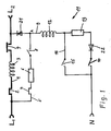
- the circuit breaker according to the invention shown in FIG. 1, 2 or 3 is arranged three times for a three-phase line, for example in a distribution system in each case between a backup fuse element, which is also a circuit breaker, and a group of downstream protective devices (circuit breakers).
- the circuit breaker should be selective both for the back-up fuse element and for the downstream circuit breakers.
- a main current path 1 leads through the circuit breaker, in which a slow movement mechanism (thermal release 2) responding to overcurrent, a faster movement mechanism responding to short circuit (magnetic mechanism 3) and a separation point 4 actuated by the thermal release 2 and by the magnetic mechanism 3 are arranged .
- the magnetic mechanism 3 and the separation point 4 are bridged by a bypass path 5.
- a bypass path 5 In this there is an ohmic resistance stood 6 of, for example, 0.1 to 5 or even up to 10 ohms for rated currents of 6-100 A, a further slower movement mechanism (thermal release 7) and a second separation point 8.
- a further current path 9 branches off to the neutral conductor behind the separation points 4 and 8. It leads via a third separation point 10 and a further faster movement mechanism (magnet mechanism 11).
- the thermal trigger 2 acts on the second disconnection point 8 via a switch lock (not shown). This is mechanically coupled via a further switch lock to the separation point 4 in such a way that the separation point 4 can open and close independently of the second separation point 8, but when the second separation point 8 also opens.
- the further thermal release 7 likewise acts on the second separation point 8 via the first-mentioned switching lock 16.
- the magnetic mechanism 3 also acts mechanically and via the further switching lock on the separation point 4.
- the further magnetic mechanism 11 acts mechanically on the separation point 4.
- the third separation point 10 is mechanically coupled to the separation point 4 so that one opens when the other closes.
- it is mechanically coupled to the second separation point 8 in such a way that it opens with it and is closed when actuated by hand.
- the main current path 1 is disconnected at the disconnection point 4 actuated by means of the faster movement mechanism (magnetic mechanism 3) which responds to the short circuit. In which this separation point 4 bridging bypass path 5, however, continues to flow, but current reduced by resistor 6. If the downstream circuit breaker also responds, i.e. if the short-circuit point is disconnected, the voltage at the input of the further current path, whose separating point 10 had been closed by opening the separating point 4, increases, and the further magnetic mechanism 11 is used as a device for closing the first-mentioned separating point ( 4) effective and restores the main current path.
- the faster movement mechanism magnetic mechanism 3
- the first-mentioned disconnection point 4 remains open.
- the increased current flowing through the bypass path 5 under these circumstances now allows the further slower movement mechanism (thermal trigger 7) to open the second separation point 8 and thus also to interrupt the bypass path 5.
- the third separation point 10 is opened by a corresponding mechanical coupling.
- the further current path 9 now also no longer receives any current.
- the thermal release 2 opens the first-mentioned disconnection point 4 in the event of an overcurrent.
- said further faster movement mechanism is provided with a coil 12 moving an armature when a threshold value of the current intensity is exceeded and a resistor 13 connected in series with the coil 12 and a line 14 bridging the resistor 13, which has a switching contact 15 such that it is closed during a first part of the armature movement. Without the threshold value being influenced, much more energy is then immediately available for closing the separation point 4.
- said further faster movement mechanism is provided with a coil 16 moving an armature when a threshold value of the current intensity is exceeded and a further coil 17 connected in parallel with it, preferably arranged concentrically with it, whose line 18 has a switch 19 has such that it is closed during a first part of the armature movement.
- a diode 21 is now arranged in each of the secondary flow path 5 and a diode 22 in the further current path 9 such that after the triggering (and in the present case at the same time largely or partly the rest of the device for closing the first-mentioned separation point (4th ) forming organs, ie the coil 12 and the resistor 13 or the coil 16 and the resistor 20, block.
- the third disconnection point 10 is open when the circuit breaker is completely switched off and is closed by hand when it is switched on again. If the diodes 21 and 22 were not, the further current would also be present if the circuit breaker was completely switched off, that is to say when the disconnection points 4 and 8 were open and when the disconnection point 10 was closed applied path 9, namely by the short circuit with L2. The result would be an immediate restart.
- the diode 21 now cuts the positive half-wave
- the diode 22 cuts the negative half-wave L2. So L2 does not affect.
- the further current path would in turn be practically loaded with L2 because the resistor 6 strongly throttles the current flow from L2.
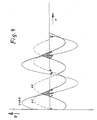
- the diodes as can be seen in Fig. 4, the current in the further current path in the event of a short circuit from L 1 to L 2 is severely limited and without a short circuit only less strongly, so that the magnetic mechanism 11 can be designed such that its threshold lies between, i.e. that it does not respond in the event of a short circuit, but can perform its restart function without a short circuit:
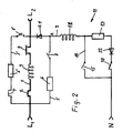
- FIG. 2 differs from that of FIG. 1 in that to the bypass path 5 with its resistor 6, its separation point 8, the branch of the further current path 9 and the diode 21, a parallel bypass path 5 'is set up with a smaller one Resistor 6 ', a separation point 8' and arranged in Fig. 1 in the bypass path 5 slower movement mechanism (thermal trigger 7).
- the separation point 8 ' is coupled to the separation point 8 such that it opens and closes together with this.
- This modification does not significantly change the potential relationships considered above.
- the resistor 6 can, however, be somewhat larger if the magnetic mechanism 11 is triggered somewhat more sensitively, and the diode 21, since it needs less current to carry, can be cheaper.
- the parallel bypass path 5 ' is effective in the progress of the closing operation after the closing of the switching contact 15, in which case the negative half-wave of L 1 can flow therein. Another advantage is that in the parallel bypass path 5 'of the diode 21 no longer impeded arrangement of the thermal release 7th
- the thermal release 7 is heated here by the current flowing in both directions and responds more quickly.
- the embodiment according to FIG. 3 corresponds to that according to FIG. 2 with the difference of the bridging by the line 18 instead of by the line 14 including the elements affected, which has already been explained above.
- this bridging known from DE-OS 34 09 513 is extended to the diode 22 provided according to the present invention, ie bridging it.
- the diode 21 and the resistor 6 are also bridged.
- the bridging and the associated amplification of the closing force of the magnetic mechanism 11 after triggering is particularly advantageous for reducing the flow of current in the bypass path 5 by setting up the parallel bypass path 5 '.
Landscapes
- Emergency Protection Circuit Devices (AREA)
Applications Claiming Priority (2)
| Application Number | Priority Date | Filing Date | Title |
|---|---|---|---|
| DE3820993A DE3820993A1 (de) | 1988-06-22 | 1988-06-22 | Schutzschalter gegen ueberstrom und kurzschluss |
| DE3820993 | 1988-06-22 |
Publications (3)
| Publication Number | Publication Date |
|---|---|
| EP0347787A2 true EP0347787A2 (fr) | 1989-12-27 |
| EP0347787A3 EP0347787A3 (fr) | 1991-07-10 |
| EP0347787B1 EP0347787B1 (fr) | 1994-12-07 |
Family
ID=6356964
Family Applications (1)
| Application Number | Title | Priority Date | Filing Date |
|---|---|---|---|
| EP89111059A Expired - Lifetime EP0347787B1 (fr) | 1988-06-22 | 1989-06-19 | Disjoncteur de protection pour courant de surcharge et court-circuit |
Country Status (2)
| Country | Link |
|---|---|
| EP (1) | EP0347787B1 (fr) |
| DE (2) | DE3820993A1 (fr) |
Cited By (1)
| Publication number | Priority date | Publication date | Assignee | Title |
|---|---|---|---|---|
| EP1137146A3 (fr) * | 2000-03-17 | 2005-10-05 | AEG Niederspannungstechnik GmbH & Co. KG | Disjoncteur sélectif |
Families Citing this family (8)
| Publication number | Priority date | Publication date | Assignee | Title |
|---|---|---|---|---|
| RU2167478C1 (ru) * | 2000-09-22 | 2001-05-20 | Закрытое акционерное общество "Компания "Транс-Сервис" | Автоматический выключатель постоянного тока |
| RU2214645C2 (ru) * | 2001-06-14 | 2003-10-20 | ООО "Технос" | Гибридный коммутационный аппарат постоянного тока |
| RU2237940C1 (ru) * | 2003-03-11 | 2004-10-10 | Общество с ограниченной ответственностью "Технос" | Способ отключения постоянного тока неполяризованным сильноточным контактным аппаратом и устройство для его осуществления |
| RU2375779C1 (ru) * | 2008-04-03 | 2009-12-10 | Общество с ограниченной ответственностью "Технос" | Способ отключения постоянного тока гибридным коммутационным устройством постоянного тока и гибридное коммутационное устройство постоянного тока для осуществления этого способа |
| DE102008026813B4 (de) * | 2008-06-05 | 2016-11-17 | Hager Electro S.A.S. | Elektrischer selektiver Selbstschalter |
| RU2382434C1 (ru) * | 2009-01-20 | 2010-02-20 | Общество с ограниченной ответственностью "Технос" | Усовершенствованное гибридное коммутационное устройство постоянного тока |
| RU2406178C1 (ru) * | 2009-06-11 | 2010-12-10 | Общество с ограниченной ответственностью "Технос" | Устройство магнитного дутья коммутационного аппарата |
| RU2627684C1 (ru) * | 2016-07-07 | 2017-08-10 | Открытое Акционерное Общество "Научно-Исследовательский И Проектно-Конструкторский Институт Информатизации, Автоматизации И Связи На Железнодорожном Транспорте" | Автономное устройство отключения источника электроснабжения |
Family Cites Families (2)
| Publication number | Priority date | Publication date | Assignee | Title |
|---|---|---|---|---|
| DE2930960A1 (de) * | 1979-07-31 | 1981-02-19 | Bbc Brown Boveri & Cie | Selektivschutzeinrichtung |
| DE3316230C2 (de) * | 1982-05-15 | 1985-04-25 | Hager Electro GmbH + Co, 6601 Ensheim | Schutzschalter gegen Überstrom und Kurzschluß |
-
1988
- 1988-06-22 DE DE3820993A patent/DE3820993A1/de not_active Withdrawn
-
1989
- 1989-06-19 EP EP89111059A patent/EP0347787B1/fr not_active Expired - Lifetime
- 1989-06-19 DE DE58908716T patent/DE58908716D1/de not_active Expired - Fee Related
Cited By (1)
| Publication number | Priority date | Publication date | Assignee | Title |
|---|---|---|---|---|
| EP1137146A3 (fr) * | 2000-03-17 | 2005-10-05 | AEG Niederspannungstechnik GmbH & Co. KG | Disjoncteur sélectif |
Also Published As
| Publication number | Publication date |
|---|---|
| EP0347787A3 (fr) | 1991-07-10 |
| DE58908716D1 (de) | 1995-01-19 |
| DE3820993A1 (de) | 1989-12-28 |
| EP0347787B1 (fr) | 1994-12-07 |
Similar Documents
| Publication | Publication Date | Title |
|---|---|---|
| DE19601540C2 (de) | Elektrisches Verteilungssystem | |
| DE69216179T2 (de) | Elektrisches Leistungsversorgungssystem | |
| DE69827108T2 (de) | Stromkreisunterbrecher mit pic (kaltleiter) elementen | |
| DE2503523A1 (de) | Wechselstrom-leistungsversorgungssystem | |
| DE102019203977B4 (de) | Schutzschalteinrichtung für Gleichspannung und Gleichspannungsabzweig mit Schutzschalteinrichtung | |
| DE2127377B2 (de) | Sicherungsautomat mit schaltspule und bimetallelement | |
| DE2854616C2 (de) | Selektivschutzeinrichtung | |
| EP0347787B1 (fr) | Disjoncteur de protection pour courant de surcharge et court-circuit | |
| EP0448505B1 (fr) | Dispositif entraîné pour une batterie | |
| DE69510717T2 (de) | Überstromschutzvorrichtung | |
| DE2930960A1 (de) | Selektivschutzeinrichtung | |
| EP1266435B1 (fr) | Procede de reenclenchement automatique du courant et installation de reenclenchement automatique | |
| DE3316230C2 (de) | Schutzschalter gegen Überstrom und Kurzschluß | |
| DE4040359A1 (de) | Einrichtung zum kurzschlussschutz | |
| DE3133200A1 (de) | Leitungsschutzschalter, geeignet als vorautomat | |
| DE19516616C1 (de) | Anordnung mit einem an ein elektrisches Energieversorgungsnetz über einen Leistungsschalter angeschlossenen Leitungsabgang mit mindestens einem Verbraucher und mit einer Unterspannungs-Schutzanordnung | |
| DE1588497A1 (de) | Schaltkombination,sogenannte Schalterkaskade,mit mindestens zwei in Reihe liegenden Kontaktsystemen | |
| CH660647A5 (de) | Leitungs- und/oder geraeteschutzschalter gegen ueberstrom und kurzschluss. | |
| DE2702181A1 (de) | Kurzschluss-schutzschaltung fuer geraete mit halbleiterschaltern, insbesondere fuer lichtsteuergeraete | |
| DE844612C (de) | UEberstromzeitrelais | |
| DE2945683A1 (de) | Leitungsschalter | |
| EP0504463A1 (fr) | Circuit pour alimentation en courant | |
| DE1563825A1 (de) | Fehlerstromschutzschalter | |
| AT295629B (de) | Sicherungseinrichtung für Freileitungsnetze mittlerer Spannung | |
| EP0980128B1 (fr) | Déclencheur à manque de tension |
Legal Events
| Date | Code | Title | Description |
|---|---|---|---|
| PUAI | Public reference made under article 153(3) epc to a published international application that has entered the european phase |
Free format text: ORIGINAL CODE: 0009012 |
|
| AK | Designated contracting states |
Kind code of ref document: A2 Designated state(s): CH DE FR GB IT LI |
|
| PUAL | Search report despatched |
Free format text: ORIGINAL CODE: 0009013 |
|
| AK | Designated contracting states |
Kind code of ref document: A3 Designated state(s): CH DE FR GB IT LI |
|
| 17P | Request for examination filed |
Effective date: 19911128 |
|
| 17Q | First examination report despatched |
Effective date: 19940308 |
|
| RAP1 | Party data changed (applicant data changed or rights of an application transferred) |
Owner name: HAGER ELECTRO GMBH |
|
| GRAA | (expected) grant |
Free format text: ORIGINAL CODE: 0009210 |
|
| AK | Designated contracting states |
Kind code of ref document: B1 Designated state(s): CH DE FR GB IT LI |
|
| ITF | It: translation for a ep patent filed | ||
| REF | Corresponds to: |
Ref document number: 58908716 Country of ref document: DE Date of ref document: 19950119 |
|
| ET | Fr: translation filed | ||
| GBT | Gb: translation of ep patent filed (gb section 77(6)(a)/1977) |
Effective date: 19950210 |
|
| PLBE | No opposition filed within time limit |
Free format text: ORIGINAL CODE: 0009261 |
|
| STAA | Information on the status of an ep patent application or granted ep patent |
Free format text: STATUS: NO OPPOSITION FILED WITHIN TIME LIMIT |
|
| 26N | No opposition filed | ||
| PGFP | Annual fee paid to national office [announced via postgrant information from national office to epo] |
Ref country code: CH Payment date: 19960429 Year of fee payment: 8 |
|
| PGFP | Annual fee paid to national office [announced via postgrant information from national office to epo] |
Ref country code: FR Payment date: 19960517 Year of fee payment: 8 |
|
| PGFP | Annual fee paid to national office [announced via postgrant information from national office to epo] |
Ref country code: GB Payment date: 19960603 Year of fee payment: 8 |
|
| PG25 | Lapsed in a contracting state [announced via postgrant information from national office to epo] |
Ref country code: GB Free format text: LAPSE BECAUSE OF NON-PAYMENT OF DUE FEES Effective date: 19970619 |
|
| PG25 | Lapsed in a contracting state [announced via postgrant information from national office to epo] |
Ref country code: LI Free format text: LAPSE BECAUSE OF NON-PAYMENT OF DUE FEES Effective date: 19970630 Ref country code: CH Free format text: LAPSE BECAUSE OF NON-PAYMENT OF DUE FEES Effective date: 19970630 |
|
| GBPC | Gb: european patent ceased through non-payment of renewal fee |
Effective date: 19970619 |
|
| REG | Reference to a national code |
Ref country code: CH Ref legal event code: PL |
|
| PG25 | Lapsed in a contracting state [announced via postgrant information from national office to epo] |
Ref country code: FR Free format text: LAPSE BECAUSE OF NON-PAYMENT OF DUE FEES Effective date: 19980227 |
|
| REG | Reference to a national code |
Ref country code: FR Ref legal event code: ST |
|
| REG | Reference to a national code |
Ref country code: FR Ref legal event code: ST |
|
| PGFP | Annual fee paid to national office [announced via postgrant information from national office to epo] |
Ref country code: DE Payment date: 20030701 Year of fee payment: 15 |
|
| PG25 | Lapsed in a contracting state [announced via postgrant information from national office to epo] |
Ref country code: DE Free format text: LAPSE BECAUSE OF NON-PAYMENT OF DUE FEES Effective date: 20050101 |
|
| PG25 | Lapsed in a contracting state [announced via postgrant information from national office to epo] |
Ref country code: IT Free format text: LAPSE BECAUSE OF NON-PAYMENT OF DUE FEES Effective date: 20050619 |