EP0347580A2 - Schmiersystem mit Spritzkühlung der Kolben einer Brennkraftmaschine - Google Patents
Schmiersystem mit Spritzkühlung der Kolben einer Brennkraftmaschine Download PDFInfo
- Publication number
- EP0347580A2 EP0347580A2 EP89108801A EP89108801A EP0347580A2 EP 0347580 A2 EP0347580 A2 EP 0347580A2 EP 89108801 A EP89108801 A EP 89108801A EP 89108801 A EP89108801 A EP 89108801A EP 0347580 A2 EP0347580 A2 EP 0347580A2
- Authority
- EP
- European Patent Office
- Prior art keywords
- combustion engine
- internal combustion
- lubricating oil
- camshafts
- spray nozzles
- Prior art date
- Legal status (The legal status is an assumption and is not a legal conclusion. Google has not performed a legal analysis and makes no representation as to the accuracy of the status listed.)
- Granted
Links
- 238000002485 combustion reaction Methods 0.000 title claims abstract description 31
- 238000005461 lubrication Methods 0.000 title claims abstract description 28
- 238000001816 cooling Methods 0.000 title claims abstract description 22
- 239000007921 spray Substances 0.000 claims abstract description 33
- 239000000314 lubricant Substances 0.000 claims abstract description 30
- 239000010687 lubricating oil Substances 0.000 claims abstract description 30
- 239000003921 oil Substances 0.000 claims description 11
- 230000002349 favourable effect Effects 0.000 abstract description 2
- 230000001105 regulatory effect Effects 0.000 abstract description 2
- 238000004519 manufacturing process Methods 0.000 description 1
- 238000005507 spraying Methods 0.000 description 1
Images
Classifications
-
- F—MECHANICAL ENGINEERING; LIGHTING; HEATING; WEAPONS; BLASTING
- F01—MACHINES OR ENGINES IN GENERAL; ENGINE PLANTS IN GENERAL; STEAM ENGINES
- F01P—COOLING OF MACHINES OR ENGINES IN GENERAL; COOLING OF INTERNAL-COMBUSTION ENGINES
- F01P3/00—Liquid cooling
- F01P3/06—Arrangements for cooling pistons
- F01P3/08—Cooling of piston exterior only, e.g. by jets
-
- F—MECHANICAL ENGINEERING; LIGHTING; HEATING; WEAPONS; BLASTING
- F01—MACHINES OR ENGINES IN GENERAL; ENGINE PLANTS IN GENERAL; STEAM ENGINES
- F01M—LUBRICATING OF MACHINES OR ENGINES IN GENERAL; LUBRICATING INTERNAL COMBUSTION ENGINES; CRANKCASE VENTILATING
- F01M1/00—Pressure lubrication
- F01M1/16—Controlling lubricant pressure or quantity
-
- F—MECHANICAL ENGINEERING; LIGHTING; HEATING; WEAPONS; BLASTING
- F01—MACHINES OR ENGINES IN GENERAL; ENGINE PLANTS IN GENERAL; STEAM ENGINES
- F01M—LUBRICATING OF MACHINES OR ENGINES IN GENERAL; LUBRICATING INTERNAL COMBUSTION ENGINES; CRANKCASE VENTILATING
- F01M9/00—Lubrication means having pertinent characteristics not provided for in, or of interest apart from, groups F01M1/00 - F01M7/00
- F01M9/10—Lubrication of valve gear or auxiliaries
-
- F—MECHANICAL ENGINEERING; LIGHTING; HEATING; WEAPONS; BLASTING
- F01—MACHINES OR ENGINES IN GENERAL; ENGINE PLANTS IN GENERAL; STEAM ENGINES
- F01M—LUBRICATING OF MACHINES OR ENGINES IN GENERAL; LUBRICATING INTERNAL COMBUSTION ENGINES; CRANKCASE VENTILATING
- F01M11/00—Component parts, details or accessories, not provided for in, or of interest apart from, groups F01M1/00 - F01M9/00
- F01M11/02—Arrangements of lubricant conduits
-
- F—MECHANICAL ENGINEERING; LIGHTING; HEATING; WEAPONS; BLASTING
- F01—MACHINES OR ENGINES IN GENERAL; ENGINE PLANTS IN GENERAL; STEAM ENGINES
- F01M—LUBRICATING OF MACHINES OR ENGINES IN GENERAL; LUBRICATING INTERNAL COMBUSTION ENGINES; CRANKCASE VENTILATING
- F01M9/00—Lubrication means having pertinent characteristics not provided for in, or of interest apart from, groups F01M1/00 - F01M7/00
- F01M9/10—Lubrication of valve gear or auxiliaries
- F01M9/102—Lubrication of valve gear or auxiliaries of camshaft bearings
-
- F—MECHANICAL ENGINEERING; LIGHTING; HEATING; WEAPONS; BLASTING
- F02—COMBUSTION ENGINES; HOT-GAS OR COMBUSTION-PRODUCT ENGINE PLANTS
- F02B—INTERNAL-COMBUSTION PISTON ENGINES; COMBUSTION ENGINES IN GENERAL
- F02B2275/00—Other engines, components or details, not provided for in other groups of this subclass
- F02B2275/34—Lateral camshaft position
Definitions
- the invention relates to a lubrication system with spray cooling of the pistons of an internal combustion engine according to the preamble of claim 1, as it is, for example, from the dissertation by Stefan Zima, approved by the department 11 design and manufacture of the Technical University of Berlin, on the "Development of high-speed high-performance engines in Friedrichshafen", volume 2 , 1984, page 551, emerges as known.
- Control valves are used for this purpose, which, depending on the lubricant pressure, stop the passage of lubricating oil to the spray nozzles and of which one is assigned to each spray nozzle.
- Such spray nozzles with assigned control valves are described for example in DE-OS 16 01 435.
- the disadvantage is that the spray nozzles in connection with the control valves represent expensive and complex components.
- the object of the invention is to ensure the lubrication of the main lubrication points of the internal combustion engine in the starting phase, but to use simple spray nozzles without integrated control valves for piston cooling, and to keep the effort for the system for piston cooling small overall.
- the supply of lubricant to the lubrication points of the camshafts can be dispensed with up to a small, reduced amount or even completely a time after the internal combustion engine has been started.
- the supply of a minimal amount of oil or at the lubrication points of the Camshafts do not take any residual oil oil supply.
- the interruption of the piston cooling in other operating states than in the start phase is not necessary if the lubricant pump has sufficient delivery capacity. Excessive cooling of the pistons cannot take place when the internal combustion engine is idling, even with uninterrupted cooling, if, as is customary in today's engines, the oil temperature is regulated by thermostats.
- the spray nozzles are no longer arranged in the confined, poorly accessible central crankcase area above the crankshaft, but in more accessible, less spatially confined side areas of the crankcase in which the camshafts lie.
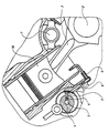
- FIGURE shows a fragmentary cross-sectional view in the area of a cylinder of an internal combustion engine with V-shaped cylinders.
- a central main channel 1 which is arranged in the V between the rows of cylinders of the internal combustion engine, serves to supply the lubrication points on the crankshaft 2 and the connecting rods 3, as well as further lubrication points of the internal combustion engine.
- the lines branching from the main channel 1 and channels to the lubrication points are not shown in detail.
- lubricant channels 5 designed as longitudinal bores are used in the camshafts 4.
- One of the lubricant channels 5 Camshaft 4 lead bores 6 to the lubrication points on the outer surface of the camshaft 4.
- the lubricating oil After emerging from the lubrication surfaces of the camshaft bearings, the lubricating oil reaches ring grooves 7 which are connected to the spray nozzles 9 for piston cooling via oil supply lines 8.
- the lubricating oil emerging from the spray nozzles 9 and dripping from the pistons 10 enters a common lubricant sump of the internal combustion engine, from where it is supplied to the lubrication points of the internal combustion engine in a new circuit by a lubricant pump (not shown).
- the lubricant channels 5, however, are not assigned control valves via which, depending on the lubricant pressure, for example, the lubricant supply to the lubricant channels 5 can be reduced or switched off in the starting phase of the internal combustion engine.
- the control valves each have a closable main bore and, if necessary, a bypass bore, which allows a reduced lubricant flow.
- the cross-section of the main bore is much larger than that of the bypass bore. It has been shown that the bearing points on the camshafts 4 and also the lubrication points of the valve control survive a sharp reduction in the lubricating oil supply in the start-up or warm-up phase of the internal combustion engine without damage.
- the spray nozzles 9 can be designed as simple components without an integrated control valve in each case. It is also advantageous that in the V-engine shown, the spray nozzles 9 are no longer arranged in the central area of the main channel 1, in which area there is very limited space, but are on the side of the crankcase in the area of the lubricant channels 5, where the accessibility and the spatial conditions are much more favorable.
- a separate lubricant line which is used solely for supplying cooling oil to the spray nozzles 9, can be dispensed with, and the control of the supply of lubricating oil to the spray nozzles can nevertheless take place by means of a central control valve.
Landscapes
- Engineering & Computer Science (AREA)
- Mechanical Engineering (AREA)
- General Engineering & Computer Science (AREA)
- Chemical & Material Sciences (AREA)
- Combustion & Propulsion (AREA)
- Lubrication Of Internal Combustion Engines (AREA)
Abstract
Description
- Die Erfindung betrifft ein Schmiersystem mit Spritzkühlung der Kolben einer Brennkraftmaschine nach dem Oberbegriff von Anspruch 1, wie es beispielsweise aus der vom Fachbereich 11 Konstruktion und Fertigung der Technischen Universität Berlin genehmigten Dissertation von Stefan Zima über die "Entwicklung schnellaufender Hochleistungsmotoren in Friedrichshafen", Band 2, 1984, Seite 551, als bekannt hervorgeht.
- In der eingangs zitierten Dissertation von Stefan Zima ist der Querschnitt einer Brennkraftmaschine dargestellt, bei der die Schmierölversorgung der Schmierstellen an Kurbelwelle und Pleuelstangen über einen zentralen Hauptkanal erfolgt, an den auch die Spritzdüsen zur Kolbenkühlung angeschlossen sind. Dazu separate Schmiermittelkanäle, die in den Nockenwellen als Längsbohrungen ausgebildet sind, dienen zur Zuführung von Schmieröl zu den Schmierstellen an den Nockenwellen und der Ventilsteuerung der Brennkraftmaschine. Bei Brennkraftmaschinen, bei denen die Spritzdüsen an den Hauptkanal angeschlossen sind, wird, um genügend Schmieröl für die Schmierung der Schmierstellen der Brennkraftmaschine zur Verfügung zu haben, nach dem Start und im Leerlauf die Kolbenkühlung ausgesetzt. Hierzu dienen Regelventile, die abhängig vom Schmiermitteldruck den Durchtritt von Schmieröl zu den Spritzdüsen stoppen, und von denen jeweils jeder Spritzdüse eines zugeordnet ist. Solche Spritzdüsen mit zugeordneten Regelventilen sind beispielsweise in der DE-OS 16 01 435 beschrieben. Nachteilig ist, daß die Spritzdüsen in Verbindung mit den Regelventilen teuere und aufwendige Bauteile darstellen.
- Aus der DE-PS 27 20 034 ist es bekannt, die Spritzdüsen zur Kolbenkühlung einem separaten Schmiermittelkanal zuzuordnen, der allein zur Zuführung von Kühlöl zu den Spritzdüsen dient. Zur Unterbrechung der Kolbenkühlung dient ein einziges Regelventil, durch das in den entsprechenden Betriebszuständen der Brennkraftmaschine die Kühlölzufuhr zum Schmiermittelkanal und damit zu allen Spritzdüsen auf einmal abgeschaltet wird. Nachteilig ist, daß ein separater Schmiermittelkanal vorgesehen werden muß, der allein zur Zuleitung von Kühlöl zu den Spritzdüsen dient. Bei den beengten Raumverhältnissen in den modernen Motoren läßt sich ein zusätzlicher Schmierölkanal, der sich über die ganze Länge des Motors erstreckt, in der Regel nur unter Inkaufnahme anderer Nachteile ausführen.
- Der Erfindung liegt die Aufgabe zugrunde, in der Startphase die Schmierung der Hauptschmierstellen der Brennkraftmaschine sicherzustellen, zur Kolbenkühlung aber einfache Spritzdüsen ohne integrierte Regelventile zu verwenden, und insgesamt den Aufwand für das System zur Kolbenkühlung klein zu halten.
- Diese Aufgabe wird bei einer gattungsgemäßen Einrichtung durch die kennzeichnenden Merkmale des Anspruchs 1 gelöst. Im Gegensatz zu den anderen Schmierstellen der Brennkraftmaschine, kann auf die Zufuhr von Schmiermittel zu den Schmierstellen der Nockenwellen bis auf eine geringe, reduzierte Menge oder sogar vollständig eine Zeit nach dem Anlassen der Brennkraftmaschine verzichtet werden. Die Zufuhr einer minimalen Ölmenge bzw. das an den Schmierstellen der Nockenwellen vorhandene Restöl Ölzufuhr auch nicht statt. Die Unterbrechung der Kolbenkühlung in anderen Betriebszuständen als in der Startphase ist bei ausreichender Förderleistung der Schmiermittelpumpe nicht notwendig. Eine zu starke Abkühlung der Kolben kann im Leerlauf der Brennkraftmaschine auch bei ununterbrochener Kühlung nicht erfolgen, wenn, wie bei heutigen Motoren üblich, die Öltemperatur durch Thermostate geregelt ist.
- Besonders vorteilhaft ist, daß die Spritzdüsen nicht mehr im räumlich beengten, schlecht zugänglichen zentralen Kurbelgehäusebereich oberhalb der Kurbelwelle angeordnet sind, sondern in besser zugänglichen, räumlich weniger beengten Seitenbereichen des Kurbelgehäuses, in denen die Nockenwellen liegen.
- Die Erfindung wird anhand eines in einer Zeichnung dargestellten Ausführungsbeispiels näher erläutert. Es zeigt die einzige Figur eine fragmentarische Querschnittsansicht im Bereich eines Zylinders einer Brennkraftmaschine mit V-förmig angeordneten Zylindern.
- Bei der in der Figur dargestellten fragmentarischen Querschnittsansicht einer Brennkraftmaschine dient ein zentraler Hauptkanal 1, der im V zwischen den Zylinderreihen der Brennkraftmaschine angeordnet ist, zur Versorgung der Schmierstellen an der Kurbelwelle 2 und den Pleuelstangen 3, sowie weiterer Schmierstellen der Brennkraftmaschine. Die vom Hauptkanal 1 abzweigenden Leitungen und Kanäle zu den Schmierstellen sind nicht näher dargestellt. Zur Schmierölversorgung der Schmierstellen an den Nockenwellen 4 und eventuell auch der nicht dargestellten Ventilsteuerung dienen in den Nockenwellen 4 als Längsbohrungen ausgebildete Schmiermittelkanäle 5. Vom Schmiermittelkanal 5 einer Nockenwelle 4 führen Bohrungen 6 zu den Schmierstellen an der Außenoberfläche der Nockenwelle 4. Nach dem Austritt von den Schmierflächen der Nockenwellenlager gelangt das Schmieröl in Ringnuten 7, die über Ölzufuhrleitungen 8 mit den Spritzdüsen 9 zur Kolbenkühlung verbunden sind. Das aus den Spritzdüsen 9 austretende und von den Kolben 10 abtropfende Schmieröl gelangt in einen gemeinsamen Schmiermittelsumpf der Brennkraftmaschine, von wo es durch eine nicht dargestellte Schmiermittelpumpe in erneutem Kreislauf den Schmierstellen der Brennkraftmaschine zugeführt wird.
- Den Schmiermittelkanälen 5 sind, wie jedoch nicht dargestellt, Regelventile zugeordnet, über die, beispielsweise abhängig vom Schmiermitteldruck, die Schmiermittelzufuhr zu den Schmiermittelkanälen 5 in der Startphase der Brennkraftmaschine reduziert oder abgeschaltet werden kann. Die Regelventile besitzen jeweils eine verschließbare Hauptbohrung und gegebenenfalls eine Umgehungsbohrung, die einen reduzierten Schmiermittelfluß zuläßt. Der Querschnitt der Hauptbohrung ist dabei wesentlich größer als der der Umgehungsbohrung. Es hat sich gezeigt, daß die Lagerstellen an den Nockenwellen 4 und auch die Schmierstellen der Ventilsteuerung eine starke Reduzierung der Schmierölzufuhr in der Start- bzw. Warmlaufphase der Brennkraftmaschine unbeschadet überstehen. In der Regel ist an den genannten Schmierstellen ausreichend Restöl zur Schmierung vorhanden, so daß sogar eine gänzliche Abschaltung der Schmierölzufuhr möglich wäre. Der Schmiermittelbedarf in der Startphase erlaubt es aber die Schmierölversorgung der Nockenwellen 4 mit der Schmierölversorgung der Spritzdüsen 9 zu koppeln, denn in der Startphase soll eine Kolbenkühlung nicht stattfinden, weshalb hierzu kein Schmieröl benötigt wird. Die an den Nockenwellen benötigte reduzierte Schmiermittelmenge reicht zur Ausbildung von Spritzstrahlen an den Spritzdüsen nicht aus. Da die Reduzierung der Schmierölversorgung zu den Nockenwellen 4 durch zentrale, den Schmiermittelkanälen 5 zugeordnete Regelventile erfolgt, ergibt sich hieraus der Vorteil, daß die Spritzdüsen 9 als einfache Bauteile ohne jeweils integriertes Regelventil ausgebildet sein können. Vorteilhaft ist auch, daß bei dem dargestellten V-Motor die Spritzdüsen 9 nicht mehr im zentralen Bereich beim Hauptkanal 1 angeordnet sind, in welchem Bereich sehr beengte Raumverhältnisse herrschen, sondern auf den Seiten des Kurbelgehäuses im Bereich der Schmiermittelkanäle 5 liegen, wo die Zugänglichkeit und die Raumverhältnisse wesentlich günstiger sind. Vorteilhaft ist natürlich auch, daß auf eine separate Schmiermittelleitung, die allein zur Zuleitung von Kühlöl zu den Spritzdüsen 9 dient, verzichtet werden kann, und die Regelung der Zufuhr von Schmieröl zu den Spritzdüsen dennoch durch eine zentrales Regelventil erfolgen kann.
- Bei warmgelaufenem Motor ist eine Reduzierung oder Abschaltung der Schmierölzufuhr zu den Nockenwellen 4 nicht vorgesehen. Die Spritzdüsen 9 bleiben also auch im Leerlauf der Brennkraftmaschine an die Schmierölversorgung angeschlossen. Durch eine ausreichend dimensionierte Schmiermittelpumpe ist dafür gesorgt, daß dennoch alle Schmierstellen der Brennkraftmaschine ausreichend mit Schmieröl versorgt werden. Eine zu starke Abkühlung der Kolben 10 der Brennkraftmaschine durch ununterbrochenes Anspritzen mit Schmieröl ist nicht zu befürchten, wenn der Motor mit einem Thermostaten oder anderen geeigneten Einrichtungen ausgerüstet ist, die die Schmieröltemperatur nicht unter einen vorbestimmten Wert absinken lassen.
Claims (3)
Applications Claiming Priority (2)
| Application Number | Priority Date | Filing Date | Title |
|---|---|---|---|
| DE3821302 | 1988-06-24 | ||
| DE3821302A DE3821302C1 (de) | 1988-06-24 | 1988-06-24 |
Publications (3)
| Publication Number | Publication Date |
|---|---|
| EP0347580A2 true EP0347580A2 (de) | 1989-12-27 |
| EP0347580A3 EP0347580A3 (en) | 1990-03-14 |
| EP0347580B1 EP0347580B1 (de) | 1992-06-24 |
Family
ID=6357140
Family Applications (1)
| Application Number | Title | Priority Date | Filing Date |
|---|---|---|---|
| EP89108801A Expired - Lifetime EP0347580B1 (de) | 1988-06-24 | 1989-05-17 | Schmiersystem mit Spritzkühlung der Kolben einer Brennkraftmaschine |
Country Status (4)
| Country | Link |
|---|---|
| US (1) | US4936417A (de) |
| EP (1) | EP0347580B1 (de) |
| DE (2) | DE3821302C1 (de) |
| ES (1) | ES2033047T3 (de) |
Cited By (1)
| Publication number | Priority date | Publication date | Assignee | Title |
|---|---|---|---|---|
| EP0659989A1 (de) * | 1993-12-23 | 1995-06-28 | Mercedes-Benz Ag | Vorrichtung zur Zufuhr von Flüssigkeiten in einen Kolben |
Families Citing this family (11)
| Publication number | Priority date | Publication date | Assignee | Title |
|---|---|---|---|---|
| DE4314183A1 (de) * | 1993-04-29 | 1994-07-07 | Audi Ag | Vorrichtung zum Schmieren der Nocken einer Nockenwelle |
| GB2340578A (en) * | 1998-08-13 | 2000-02-23 | Cummins Engine Co Ltd | Mounting a nozzle on an engine block to direct cooling oil at the underside of a reciprocating piston |
| IL157032A (en) * | 2003-07-21 | 2007-10-31 | Moshe Elbaz | Cutting head for rotary cutting tool |
| DE102004050235A1 (de) * | 2004-10-15 | 2006-04-20 | Daimlerchrysler Ag | Brennkraftmaschine |
| ES2545753T3 (es) * | 2012-04-17 | 2015-09-15 | Fpt Industrial S.P.A. | Método para controlar un circuito de refrigeración de pistones de un motor de combustión interna de un vehículo industrial |
| CN103470357B (zh) * | 2013-06-24 | 2016-01-20 | 浙江吉利汽车研究院有限公司杭州分公司 | 一种发动机活塞冷却喷嘴结构及控制方法 |
| US9605620B2 (en) | 2015-04-16 | 2017-03-28 | Ford Global Technologies, Llc | Systems and methods for piston cooling |
| KR102463186B1 (ko) * | 2016-12-13 | 2022-11-03 | 현대자동차 주식회사 | 차량용 피스톤 냉각 장치 |
| DE102017001615B3 (de) | 2017-02-18 | 2018-05-09 | Mtu Friedrichshafen Gmbh | Brennkraftmaschine mit Spritzölkühlung und Verfahren |
| DE102017120727A1 (de) * | 2017-09-08 | 2019-03-14 | Man Truck & Bus Ag | Verfahren und Vorrichtung zur Kühlung und/oder Schmierung eines Kolbens und/oder der Laufbahn eines Zylinders einer Hubkolbenbrennkraftmaschine |
| CN119288653A (zh) * | 2024-11-19 | 2025-01-10 | 河南柴油机重工有限责任公司 | 一种柴油机活塞冷却喷嘴装置 |
Family Cites Families (9)
| Publication number | Priority date | Publication date | Assignee | Title |
|---|---|---|---|---|
| US1996817A (en) * | 1934-01-31 | 1935-04-09 | Briggs & Stratton Corp | Oiling system for internal combustion engines |
| DE708798C (de) * | 1939-02-18 | 1941-07-29 | Waggon Und Maschb Akt Ges Goer | Treibstangenlager mit in der Lagerflaeche angeordneter OElnut |
| US2678702A (en) * | 1950-11-30 | 1954-05-18 | Allis Chalmers Mfg Co | Bearing lubrication |
| US2800119A (en) * | 1955-05-05 | 1957-07-23 | Maschf Augsburg Nuernberg Ag | Arrangement for cooling the piston of internal combustion engines |
| US2991770A (en) * | 1959-07-15 | 1961-07-11 | Gen Motors Corp | Piston cooling means |
| DE1216014B (de) * | 1961-02-09 | 1966-05-05 | Int Harvester Co | Umlaufsystem zur Schmierung und Kolbenkuehlung von Brennkraftmaschinen |
| DE1934378U (de) * | 1965-10-28 | 1966-03-10 | Degussa | Vorrichtung zur katalytischen reinigung der abgase von brennkraftmaschinen. |
| DE1601435A1 (de) * | 1968-02-14 | 1970-10-29 | Daimler Benz Ag | Vorrichtung zur Regelung der Kolbenkuehlung von Brennkraftmaschinen |
| US4058981A (en) * | 1976-06-04 | 1977-11-22 | Caterpillar Tractor Co. | Lubricating system and method for turbocharged engines |
-
1988
- 1988-06-24 DE DE3821302A patent/DE3821302C1/de not_active Expired
-
1989
- 1989-05-17 ES ES198989108801T patent/ES2033047T3/es not_active Expired - Lifetime
- 1989-05-17 DE DE8989108801T patent/DE58901738D1/de not_active Expired - Lifetime
- 1989-05-17 EP EP89108801A patent/EP0347580B1/de not_active Expired - Lifetime
- 1989-06-20 US US07/368,798 patent/US4936417A/en not_active Expired - Fee Related
Cited By (2)
| Publication number | Priority date | Publication date | Assignee | Title |
|---|---|---|---|---|
| EP0659989A1 (de) * | 1993-12-23 | 1995-06-28 | Mercedes-Benz Ag | Vorrichtung zur Zufuhr von Flüssigkeiten in einen Kolben |
| US5503116A (en) * | 1993-12-23 | 1996-04-02 | Mercedes-Benz Ag | Arrangement for supplying liquids to a piston |
Also Published As
| Publication number | Publication date |
|---|---|
| ES2033047T3 (es) | 1993-03-01 |
| DE58901738D1 (de) | 1992-07-30 |
| US4936417A (en) | 1990-06-26 |
| DE3821302C1 (de) | 1989-06-01 |
| EP0347580A3 (en) | 1990-03-14 |
| EP0347580B1 (de) | 1992-06-24 |
Similar Documents
| Publication | Publication Date | Title |
|---|---|---|
| DE2720034C2 (de) | Schmiersystem | |
| DE3118498C2 (de) | Ölgekühlte Zylinderlaufbüchse | |
| EP0347580B1 (de) | Schmiersystem mit Spritzkühlung der Kolben einer Brennkraftmaschine | |
| EP0636772B1 (de) | Brennkraftmaschine | |
| DE112015000171T5 (de) | Motorölzufuhrvorrichtung | |
| EP2213851B1 (de) | Ölversorgungseinrichtung zum Schmieren eines Zylinders und/oder zum Kühlen eines Kolben | |
| DE102012222353B4 (de) | Ölversorgungsstruktur einer Kurbelwelle in einem Motor | |
| DE102017006755A1 (de) | Motorölzuführvorrichtung, Verfahren zum Schützen eines Ölfilters und Computerprogrammprodukt | |
| EP1070836A2 (de) | Vorrichtung zur Kühlung und/oder Schmierung einer Hubkolbenbrennkraftmaschine | |
| EP3339617A1 (de) | Zylindergehäuse, verfahren zur herstellung eines zylindergehäuses und giesskern | |
| EP0376150A2 (de) | Brennkraftmaschine mit zwei hydraulischen Flüssigkeitskreisläufen | |
| DE19962164B4 (de) | Öldurchtritt für einen Verbrennungsmotor | |
| EP1676989B1 (de) | Verbrennungsmotor mit einer Kolbenkühlvorrichtung | |
| EP3438424A1 (de) | Vorrichtung zum schmieren einer brennkraftmaschine | |
| DE10323734B4 (de) | Brennkraftmaschine mit mehreren Zylindern | |
| DE3618794C2 (de) | ||
| DE102010051761A1 (de) | Verfahren zum Abkühlen eines Hochdruckstössels | |
| DE19900132A1 (de) | Brennkraftmaschine, insbesondere dieselmotorische Viertaktbrennkraftmaschine | |
| WO2006037515A1 (de) | Vorrichtung zum regeln einer kolbenkühlung einer hubkolbenbrennkraftmaschine | |
| AT521887B1 (de) | System und Verfahren zum Einstellen einer wirksamen Länge einer Pleuelstange mittels Schmiermittelversorgung | |
| DE102004044996B4 (de) | Motorschmiersystem | |
| DE102015007510B4 (de) | Verfahren zum Betreiben einer Brennkraftmaschine und Vorrichtung zum Durchführen eines solchen Verfahrens | |
| DE102017201741B4 (de) | Kolben-Pleuel-Vorrichtung zur direkten Kolbenschmierung und -kühlung | |
| DE102012218075A1 (de) | Hochdruckpumpe, insbesondere Kraftstoffhochdruckpumpe | |
| AT5132U1 (de) | Brennkraftmaschine mit innerer verbrennung |
Legal Events
| Date | Code | Title | Description |
|---|---|---|---|
| PUAI | Public reference made under article 153(3) epc to a published international application that has entered the european phase |
Free format text: ORIGINAL CODE: 0009012 |
|
| AK | Designated contracting states |
Kind code of ref document: A2 Designated state(s): CH DE ES FR GB IT LI NL |
|
| PUAL | Search report despatched |
Free format text: ORIGINAL CODE: 0009013 |
|
| AK | Designated contracting states |
Kind code of ref document: A3 Designated state(s): CH DE ES FR GB IT LI NL |
|
| 17P | Request for examination filed |
Effective date: 19900125 |
|
| 17Q | First examination report despatched |
Effective date: 19910717 |
|
| ITF | It: translation for a ep patent filed | ||
| GRAA | (expected) grant |
Free format text: ORIGINAL CODE: 0009210 |
|
| AK | Designated contracting states |
Kind code of ref document: B1 Designated state(s): CH DE ES FR GB IT LI NL |
|
| ET | Fr: translation filed | ||
| REF | Corresponds to: |
Ref document number: 58901738 Country of ref document: DE Date of ref document: 19920730 |
|
| GBT | Gb: translation of ep patent filed (gb section 77(6)(a)/1977) | ||
| REG | Reference to a national code |
Ref country code: ES Ref legal event code: FG2A Ref document number: 2033047 Country of ref document: ES Kind code of ref document: T3 |
|
| PLBE | No opposition filed within time limit |
Free format text: ORIGINAL CODE: 0009261 |
|
| STAA | Information on the status of an ep patent application or granted ep patent |
Free format text: STATUS: NO OPPOSITION FILED WITHIN TIME LIMIT |
|
| 26N | No opposition filed | ||
| PGFP | Annual fee paid to national office [announced via postgrant information from national office to epo] |
Ref country code: CH Payment date: 19940420 Year of fee payment: 6 |
|
| PGFP | Annual fee paid to national office [announced via postgrant information from national office to epo] |
Ref country code: ES Payment date: 19940516 Year of fee payment: 6 |
|
| PGFP | Annual fee paid to national office [announced via postgrant information from national office to epo] |
Ref country code: NL Payment date: 19940531 Year of fee payment: 6 |
|
| PG25 | Lapsed in a contracting state [announced via postgrant information from national office to epo] |
Ref country code: ES Free format text: LAPSE BECAUSE OF NON-PAYMENT OF DUE FEES Effective date: 19950518 |
|
| PG25 | Lapsed in a contracting state [announced via postgrant information from national office to epo] |
Ref country code: LI Effective date: 19950531 Ref country code: CH Effective date: 19950531 |
|
| PG25 | Lapsed in a contracting state [announced via postgrant information from national office to epo] |
Ref country code: NL Effective date: 19951201 |
|
| REG | Reference to a national code |
Ref country code: CH Ref legal event code: PL |
|
| NLV4 | Nl: lapsed or anulled due to non-payment of the annual fee |
Effective date: 19951201 |
|
| REG | Reference to a national code |
Ref country code: ES Ref legal event code: FD2A Effective date: 19990201 |
|
| PGFP | Annual fee paid to national office [announced via postgrant information from national office to epo] |
Ref country code: GB Payment date: 20010412 Year of fee payment: 13 |
|
| PGFP | Annual fee paid to national office [announced via postgrant information from national office to epo] |
Ref country code: FR Payment date: 20010507 Year of fee payment: 13 |
|
| PGFP | Annual fee paid to national office [announced via postgrant information from national office to epo] |
Ref country code: DE Payment date: 20010509 Year of fee payment: 13 |
|
| REG | Reference to a national code |
Ref country code: GB Ref legal event code: IF02 |
|
| PG25 | Lapsed in a contracting state [announced via postgrant information from national office to epo] |
Ref country code: GB Free format text: LAPSE BECAUSE OF NON-PAYMENT OF DUE FEES Effective date: 20020517 |
|
| PG25 | Lapsed in a contracting state [announced via postgrant information from national office to epo] |
Ref country code: DE Free format text: LAPSE BECAUSE OF NON-PAYMENT OF DUE FEES Effective date: 20021203 |
|
| GBPC | Gb: european patent ceased through non-payment of renewal fee |
Effective date: 20020517 |
|
| PG25 | Lapsed in a contracting state [announced via postgrant information from national office to epo] |
Ref country code: FR Free format text: LAPSE BECAUSE OF NON-PAYMENT OF DUE FEES Effective date: 20030131 |
|
| REG | Reference to a national code |
Ref country code: FR Ref legal event code: ST |
|
| PG25 | Lapsed in a contracting state [announced via postgrant information from national office to epo] |
Ref country code: IT Free format text: LAPSE BECAUSE OF NON-PAYMENT OF DUE FEES;WARNING: LAPSES OF ITALIAN PATENTS WITH EFFECTIVE DATE BEFORE 2007 MAY HAVE OCCURRED AT ANY TIME BEFORE 2007. THE CORRECT EFFECTIVE DATE MAY BE DIFFERENT FROM THE ONE RECORDED. Effective date: 20050517 |