EP0346587B1 - Kabeldurchführung - Google Patents
Kabeldurchführung Download PDFInfo
- Publication number
- EP0346587B1 EP0346587B1 EP89106723A EP89106723A EP0346587B1 EP 0346587 B1 EP0346587 B1 EP 0346587B1 EP 89106723 A EP89106723 A EP 89106723A EP 89106723 A EP89106723 A EP 89106723A EP 0346587 B1 EP0346587 B1 EP 0346587B1
- Authority
- EP
- European Patent Office
- Prior art keywords
- cable
- closure part
- housing
- opening
- pot
- Prior art date
- Legal status (The legal status is an assumption and is not a legal conclusion. Google has not performed a legal analysis and makes no representation as to the accuracy of the status listed.)
- Expired - Lifetime
Links
Images

Classifications
-
- H—ELECTRICITY
- H02—GENERATION; CONVERSION OR DISTRIBUTION OF ELECTRIC POWER
- H02G—INSTALLATION OF ELECTRIC CABLES OR LINES, OR OF COMBINED OPTICAL AND ELECTRIC CABLES OR LINES
- H02G3/00—Installations of electric cables or lines or protective tubing therefor in or on buildings, equivalent structures or vehicles
- H02G3/02—Details
- H02G3/06—Joints for connecting lengths of protective tubing or channels, to each other or to casings, e.g. to distribution boxes; Ensuring electrical continuity in the joint
- H02G3/0616—Joints for connecting tubing to casing
- H02G3/0625—Joints for connecting tubing to casing with means for preventing disengagement of conductors
- H02G3/065—Joints for connecting tubing to casing with means for preventing disengagement of conductors with means biting into the conductor-insulation, e.g. teeth-like elements or gripping fingers
-
- H—ELECTRICITY
- H02—GENERATION; CONVERSION OR DISTRIBUTION OF ELECTRIC POWER
- H02G—INSTALLATION OF ELECTRIC CABLES OR LINES, OR OF COMBINED OPTICAL AND ELECTRIC CABLES OR LINES
- H02G3/00—Installations of electric cables or lines or protective tubing therefor in or on buildings, equivalent structures or vehicles
- H02G3/02—Details
- H02G3/06—Joints for connecting lengths of protective tubing or channels, to each other or to casings, e.g. to distribution boxes; Ensuring electrical continuity in the joint
- H02G3/0616—Joints for connecting tubing to casing
- H02G3/0625—Joints for connecting tubing to casing with means for preventing disengagement of conductors
- H02G3/0633—Joints for connecting tubing to casing with means for preventing disengagement of conductors with means urging the conductors to follow a non-straight line
Definitions
- the invention relates to a cable bushing for a housing containing at least one electrical component, in particular for a pulse speed sensor, according to the preamble of patent claim 1.
- a pulse speed sensor which has a two-part housing.
- the essentially cup-shaped lower housing part consists of a metallic material and the upper housing part provided as a closure part for closing the cup-shaped lower housing part, on which a cable bushing is arranged, is made of a plastic.
- the upper housing part shown in the drawing of the mentioned DE-OS 35 20 288 extends partly into the lower housing part and is formed in this area as a carrier for a pole pin, a permanent magnet and a coil surrounding the pole pin.
- the end face of the upper housing part facing away from the pole pin has a trough which can be closed by means of a cover and in which both busbars connected to the coil and conductors of an electrical cable to be connected to the busbars open.
- the cable is led out of the housing and is used for the electrical connection of the electrical component designed as a coil to an electrical device located outside the housing and arranged separately from it.
- a cable duct for said cable is arranged on the upper housing part.
- the cable entry is formed by a passage in the wall of the upper housing part.
- projections are provided which extend to the cable and which engage on the outer surface of the cable in the manner of barbs and thus serve as strain relief for the cable.
- the strain relief of the cable duct designed in this way has various disadvantages.
- the projections formed in the cable bushing may not be able to achieve a sufficient clamping effect on the cable, so that the forces that occur when the cable is subjected to tensile loads do not pass from the cable sheath via the projections arranged in the cable bushing to the housing but to the wires of the cable and the electrical component connected to them are transmitted in the housing.
- the individual wires of the cable can tear off or the electrical component in the housing can be damaged.
- a cable bushing known from DE-U-7 105 475 has a disc with an eccentrically mounted bore which serves to lead through a cable.
- the washer is pressed between a screw base serving for attachment to a wall to be penetrated by the cable and a union nut which can be screwed onto it, in such a way that the cable undergoes a strain-relieved bend at the point of passage through the washer.
- This known device has the disadvantage that when establishing the clamp connection between the cable and cable bushing Damage to the cable can occur.
- the washer which has the eccentrically arranged bushing, is rotated by the union nut, which leads to twisting or twisting of the cable and thus to a cable tear at the contact points between the cable and lead an electrical component.
- a coupling for connecting two electrical components which has a cable bushing.
- the cable bushing is composed of two components forming a structural unit, which are connected to one another by means of an articulated joint so as to be movable.
- a recess is provided in the wall of one component, into which an elevation arranged on the other component extends.
- the mutually facing sides of the elevation and the wall delimiting the depression form a channel for receiving a cable.
- the channel With a pivoting movement of the two components in such a way that the mutually facing sides of the components move apart, the channel widens so that a cable can be inserted into it. With a subsequent pivoting movement of the two components towards one another in such a way that the mutually facing sides of the components move towards one another, the channel narrows, so that the cable is pinched.
- this unit which serves as a cable bushing and at the same time as a contact carrier, is inserted into the housing of the coupling after the cable has been received in this position, the sides of the two components facing each other can no longer be separated from one another and the cable is separated by the two components the cable exerted clamping force.
- This known device has the disadvantage that during the pivoting movement of the two components relative to one another, the cable is displaced when the clamping process is initiated from the toothed elevation of one component in the direction of its longitudinal axis against the wall of the other component delimiting the recess, also provided with teeth becomes, which on the one hand can lead to damage to the cable and on the other hand makes an exact positioning of the cable to a component located in the housing almost impossible.
- the invention has for its object to provide a cable bushing of the type mentioned with a strain relief, which is designed so that a reliable strain relief on the cable is achieved.
- the invention offers the advantage, in particular, of obtaining a reliable strain relief for the cable due to the relatively large-area support of the parts of the cable bushing forming the strain relief on the wall of the pot-shaped housing part. Since the strain relief is split, manufacturing-related tolerances on the strain relief or also on the opening in the housing that receives the strain relief can be easily compensated for. No additional component is required to close the cup-shaped housing part, since at least one of the two parts of the strain relief is designed as a closure part for the cup-shaped housing part.
- the cable is elastically deformed by means of a projection on one part of the strain relief and a depression provided on the other part of the strain relief in such a way that the part of the cable located within the strain relief is one Has curve shape.
- a recess is provided in the outer lateral surface of one part of the strain relief, into which a protrusion of the wall of the pot-shaped housing part, for example by pressing it in, is provided engages, whereby the strain relief which simultaneously forms the closure part for the housing is secured in the direction of its longitudinal axis against a displacement movement.
- a first stop and a circumferential projection serving as a second stop for the cable are provided in the cable bushing, the circumferential projection being designed such that it acts on the cable in the manner of a barb.
- the first stop is arranged in the passage for the cable so that the cable rests against this stop with the end face of the cable jacket.
- the second stop is arranged opposite the first stop in the cable bushing and is designed in such a way that it is pressed into the jacket of the cable, this second stop only permitting movement of the cable in the direction of the first stop. This means that after the cable is inserted into the cable duct, the cable is fixed in the direction of its longitudinal axis.
- the second stop in the manner of a seal prevents the ingress of dirt and moisture into the part of the passage in the closure part leading to the interior of the housing.
- the strain relief advantageously has in the area of the first stop a deflecting part with a curved surface for the wire or the wires of the cable. This deflection part is used when the cable is led radially out of the housing or out of the closure part of the housing.
- the cable bushing which is provided for a radial lead-out of the cable from the housing
- the cable bushing according to an advantageous development of the invention has a part of the closure part arranged, essentially transversely to the longitudinal axis of the closure part and thus also essentially transversely to the longitudinal axis of the pot-shaped housing part extending projection with a passage for the cable, which connects to the passage provided in the closure part for the cable.
- the passage provided in the projection serves as a guide for the cable.
- the passage penetrating the projection widens in a funnel shape in its free end area leading outwards, so that the cable can be pivoted without fear of damage to the cable.
- Such an extension can of course also be provided on a closure part for the pot-shaped housing part, in which the cable is led out of the housing essentially in the direction of the longitudinal axis of the housing.
- the wall of the cup-shaped housing part advantageously has a slot which extends in the direction of the free edge region of the cup-shaped housing part.
- the slot serves to receive the projection arranged on the closure part and extending transversely to the longitudinal axis of the housing.
- the slot is dimensioned such that it extends in the direction of the longitudinal axis of the closure part over the major part of the axial extent of the closure part extends, taking up the projection, based on its largest diameter, completely.
- the slot has, inter alia, the function of an anti-rotation device for the closure part in relation to the cup-shaped housing part.
- the closure part has on its side facing away from the cup-shaped housing part a radially outwardly extending annular projection, which preferably rests in the manner of a cover on the free edge region of the cup-shaped part of the housing.
- a sealing device which has at least one sealing element consisting of an elastomer, which is designed such that it is on the one hand on the wall of the housing or on the wall of a part arranged in the housing and on the other hand directly on the core or, in the case of a multi-core cable, sealingly on the core of the cable.
- a support connected to the closure part is provided as a support or also as a carrier for the sealing element and is arranged on the side of the closure part facing the interior of the housing.
- the carrier is preferably designed as an annular body which carries a first disk-shaped sealing element and a second annular sealing element.
- the first sealing element is arranged within the space delimited by the annular body and lies on the one hand with its circumferential surface or with circumferential sealing projections arranged on its circumferential surface on the inner circumferential surface of the annular body and on the other hand has one or more passages for one or more in the direction of its longitudinal axis Cores of the cable, wherein each passage is formed and arranged so that each wall defining a passage sealingly abuts a wire of the cable.
- the inside of the second sealing element lies sealingly against the outer surface of the annular body and with its outside sealingly against the inside of the pot-shaped housing.
- the annular body serving as a carrier for the sealing elements can be designed with the closure part as an annular extension of the closure part and thus form an integral unit with the latter.
- the arrangement of a sealing element designed and arranged in this way, in cooperation with the strain relief used for the cable, has the advantage of obtaining a cable bushing which, on the one hand, ensures reliable strain relief of the cable and, on the other hand, reliable sealing of the space containing the electrical component.
- the sealing effect of the sealing element is not impaired by a tensile load even when the cable is deformed, since the sealing takes place directly on the wires of the cable.
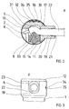
- FIG. 1 shows a housing provided with a cable bushing, in which a magnet coil, not shown, a pole pin and a permanent magnet are arranged.
- the housing consists of a cup-shaped housing part (1, 6), which has an enlarged area (6) towards its open side, and a closure part (11, 12).
- the cable duct serves to receive an electrical cable (2, 22), which consists of at least one core (2) and a sheath (22) surrounding the core (2).
- the electrical cable (2, 22) is used to connect an electrical component, such as the coil, arranged in the interior of the housing to an electrical device located outside the housing (1, 6, 11, 12).
- strain relief is required provided for the cable (2, 22).
- the strain relief essentially consists of two parts (11 and 14) which can be moved relative to one another for clamping the cable (2, 22).
- One part (11) of the strain relief is essentially formed as a cylindrical body, which is inserted with the major part of its axial extent in the enlarged area (6) of the cup-shaped housing part (1, 6).
- the protruding from the housing part (1, 6) part (12) of the part (11, 12) of the strain relief designed as a closure part is dimensioned in such a way that it rests on the edge region of the assembly opening of the housing part (1, 6) and its The peripheral surface is flush with the outer lateral surface of the enlarged area (6) of the housing part (1, 6).
- the part (11, 12) of the strain relief serving as a closure part has a projection (19) which extends essentially transversely to the longitudinal axis of the closure part (11, 12) and thus also essentially transversely to the longitudinal axis of the housing part (1, 6) the outer surface of the closure part (11, 12) is formed.
- a passage (9) for the cable (2, 22) is provided in the part (11, 12) of the strain relief serving as a closure part.
- the passage (9) is arranged essentially transversely to the longitudinal axis of the closure part (11, 12).
- the passage (9) is partly delimited by a web-like wall (7) which runs transversely to the longitudinal axis of the closure part (11, 12) and which has at its free end a deflection part (8) which has an outwardly curved surface.
- the passage (9) is followed by a further passage (20) for the cable (2, 22) arranged in the projection (19), which runs coaxially with the passage (9) provided in the closure part (11, 12).
- the passage (20) provided in the projection (19) and the passage (9) adjoining this in the closure part (11, 12) serve to receive the part of the cable (2, 22) having the sheath (22).
- recess (13) is arranged, which extends essentially from the outer surface of the closure part (11, 12) to the passage (9) and in this flows.
- a part designed as a clamping piece (14) is arranged in this recess (13) so that it can be moved towards or away from the cable (2, 22).
- the closure part (11, 12) and the clamping piece (14) together form the strain relief for the cable (2, 22).
- the clamping piece (14) is dimensioned in the direction of its longitudinal axis to be extended onto the cable (2, 22) (cable sheath 22) in such a way that after the insertion of the closure part (11) provided with the clamping piece (14) into the Pot-shaped housing part (1, 6) with its end facing away from the cable (2, 22), which in this exemplary embodiment has an outwardly extending projection (15), is supported on the inner wall of the housing part (6) and with it the cable (2 , 22) facing side with elastic deformation of the cable (2, 22) against a partial area of the wall delimiting the passage (9) for the cable (2, 22) or against a part connected to this wall, which is not shown here, presses.
- the two parts (11, 12 and 14) of the strain relief (11, 12, 14) are thus pretensioned essentially perpendicular to the wall of the cup-shaped housing part (1, 6) on the wall of the cup-shaped housing part (1, 6) .
- the recess (13) for the clamping piece (14) is arranged in the direction of the longitudinal axis of the closure part (11, 12) so that after the insertion of the closure part (11, 12) with the clamping piece into the housing part (1, 6) in the area (11) of the closure part (11, 12) surrounded by the housing part (1, 6).
- a U-shaped slot (23) is arranged in the wall of the pot-shaped housing part (1, 6) to accommodate the radially outwardly extending projection (19), as can be seen in FIG. 3.
- the slot (23) is arranged in the direction of the longitudinal axis of the pot-shaped housing part (1, 6) and is dimensioned such that it extends over the major part of the axial extent of the closure part (11, 12) and to the lid-like part ( 12) of the closure part (11, 12) pointing towards the edge of the cup-shaped housing part is open.
- the slot (23) and the projection (19) have, inter alia, the function of an anti-rotation device for the closure part (11, 12) relative to the cup-shaped housing part (1, 6).
- the passage (9) for the cable (2, 22) has a first stop for the end face of the jacket (22) of the cable (2, 22).
- the stop is composed of a step (10) and a surface of the deflection part (8) facing the end face of the jacket (22) of the cable (2, 22).
- the stop (10, 8) is arranged on the side of the passage (9) which is the free end of the passage leading out of the closure part (11, 12) (9) is opposite.
- the step (10) is sufficient as a stop if the deflection part (8) is omitted.
- a circumferential projection (17) which extends onto the jacket (22) of the cable (2, 22) and serves as a second stop.
- the circumferential projection (17) is designed in such a way that it allows the cable (2, 22) to be inserted into the passage (9) in the direction of the first stop (10) and allows the cable (2, 22) to move from the first However, stop (10) is prevented (barb principle).
- This arrangement of the stop (10) and of the circumferential projection (17) additionally fulfilling the function of a seal fixes the cable (2, 22) in the direction of its longitudinal axis. As can be seen from FIG.
- a recess (31) is provided on the side opposite the recess (13) for receiving the clamping piece (14) in the wall delimiting the passage (9), into which the cable (2, 22) is attached of the clamping piece (14) is pressed in, so that it takes a curved course in the passage (9) in this area.
- a projection (33) is provided on the side of the clamping piece (14) facing the cable (2, 22) in order to reinforce the curved deformation of the cable (2, 22), on the side of the clamping piece (14) facing the cable (2, 22) there is provided a projection (33) to be extended onto the cable (2, 22)
- Contact surface with the jacket of the cable has a contour that is adapted to the jacket surface of the cable (2, 22).
- the in the radially on the closure part (11, 12) arranged projection (19) provided passage (20) for the Cable (2, 22) serves as a guide for the cable (2, 22) and is designed in its free end area to widen outwards in the manner of a funnel (21), so that a slight pivoting movement of the cable (2, 22) is made possible without damaging the cable.
- a carrier (26) for a sealing device is provided on the side of the closure part (11, 12) facing the interior of the pot-shaped housing part (1, 6).
- the carrier (26) forms an integral unit with the closure part (11, 12).
- the sealing device serves to seal the interior of the housing with respect to the passage (9) for the cable (2, 22) and with respect to the mounting opening in the cup-shaped housing part (1, 6) for the closure part (11, 12).
- the sealing device is composed of a first sealing element and a second sealing element, which are supported on the carrier or are mounted in or on this.
- the first sealing element is designed as a disk-shaped seal (4) and is mounted in a part of the stepped recess (16, 25) in the larger diameter part of the support (26), which at the same time represents a partial area of the closure part (11, 12).
- the disc-shaped seal (4) has a passage (18) for the wire (2) of the cable (2, 22) or, in the case of a multi-core cable, a separate passage for each wire of the cable.
- the passage (18) for the wire is designed such that the wall delimiting the passage (18) or circumferential projections (3) arranged on this wall lie sealingly against the wire (2). With its peripheral surface or With circumferential projections (5) arranged on this peripheral surface, the disk-shaped seal (4) lies sealingly against the wall delimiting the recess (25) of the carrier (26).
- a circumferential groove (28) is provided in the outer lateral surface of the carrier (26), in which a sealing ring (27) serving as a second sealing element is arranged.
- the sealing ring (27) lies with its inside sealingly against the carrier (26) (in the groove 28) and with its outside sealing against the inside wall of the cup-shaped housing part (1,6).
- the first seal (4) designed as a wire seal thus seals the interior of the pot-shaped housing part (1, 6) against the passage (9) for the cable (2, 22) and against the strain relief (11, 12, 13, 14) located cavities.
- the sealing ring (27) serving as the second sealing element seals a possible gap between the inner wall of the pot-shaped housing part (1, 6) and the strain relief which simultaneously represents the closure part (11, 12) for this housing part (1, 6).
- the carrier for the sealing elements can, as mentioned above, be formed with the closure part as a one-piece structural unit, but it can also be formed as a separate part and arranged in the housing (1, 6) such that it is between the closure part and the electrical component area of the housing interior is located.
- the carrier or the support for the sealing element or for the sealing elements can be circular Have cross-section or a cross-section deviating from the circular shape, which is preferably adapted to the cross-sectional shape of the housing (1, 6).
- the clamping piece (14) cooperating with the closure part (11, 12) can have any shape.
- the recess provided in the closure part (11, 12) and used to receive the clamping piece (14) must always be so designed and dimensioned that the clamping piece (14) is securely guided in this recess.
- the projections (33 and 15) provided on the clamping piece (14) can be dispensed with.
- the clamping piece (14) is dimensioned in the direction of its axis to be extended on the cable (22, 2) so that it is so far into the passage (9) for the cable when the strain relief is installed in the housing (2, 22) that the cable (2, 22) is securely held by the clamping piece (14) and the wall of the recess of the part (11, 12) of the strain relief serving as a closure part opposite the clamping piece (14).
- a recess (34) is provided in the outer circumferential surface of the closure part (11, 12) into which a nose-like projection (35) of the housing wall produced by embossing or indentation engages (see Fig. 2 and Fig. 3).
- a plate (32) provided with a recess (36) which is mounted in a recess (30) in the lateral surface of the closure part (11, 12) is.
- the nose-like projection (35) extends through the recess (36) of the plate (32).
- the plate (32) serves to stiffen the area of the closure part (11, 12) receiving the nose-like projection (35) and additionally prevents deformation of the housing wall in the area having the nose-like projection (35) during the embossing process.
- the cable duct can of course also be designed so that the cable (2, 22) is led out of the housing (1, 6) in the direction of the longitudinal axis of the housing (1, 6) and the closure part (11, 12).
- the deflection part (8) for the wires (2) of the cable (2, 22) can be dispensed with.
- the cable entry is installed as described below.
- the cable (2, 22) is inserted through the passage (20) of the projection (19) and through the passage (9) of the closure part (11, 12) into the closure part (11, 12) until the End face of the cable sheath (22) comes to rest on the projection serving as a stop (10). Then the wires (2) of the cable (2, 22) are placed around the deflection part (8) and passed through the stepped recess (16, 25, 24) of the carrier (26) for the sealing elements (4 and 27).
- the first sealing element (4) designed as a wire seal is pushed onto the wire (2) or onto the wires (2) of the cable (2, 22) until the first sealing element (4) into the stepped recess (16, 25 , 24) of the carrier (26) is immersed and with its closing part (11, 12) End face on the surface (24) of the stepped recess (16, 25, 24) comes to rest.
- the second sealing element (27) designed as a sealing ring, was inserted into the groove (28) in the outer lateral surface of the carrier (26).
- the clamping piece (14) is inserted into the recess (13) of the closure part (11, 12) and pressed into it until the projection (15) of the clamping piece (14) is approximately flush with the adjacent area of the lateral surface of the closure part (11, 12) completes. Then the closure part (11, 12) with the clamping piece (14) towards the bottom (29) of the housing is pushed into the housing (1, 6). The lid-like part (12) of the closure part (11, 12) is placed on the edge of the housing (1, 6).
- the nose-like projection (35) of the housing wall is produced, which engages in the recess (34) in the outer surface of the closure part (11, 12).
Landscapes
- Engineering & Computer Science (AREA)
- Architecture (AREA)
- Civil Engineering (AREA)
- Structural Engineering (AREA)
- Installation Of Indoor Wiring (AREA)
- Details Of Connecting Devices For Male And Female Coupling (AREA)
- Insertion, Bundling And Securing Of Wires For Electric Apparatuses (AREA)
Description
- Die Erfindung betrifft eine Kabeldurchführung für ein wenigstens ein elektrisches Bauteil enthaltendes Gehäuse, insbesondere für einen Impulsdrehzahlgeber, gemäß dem Oberbegriff des Patentanspruchs 1.
- Aus der DE-OS 35 20 288 ist ein Impulsdrehzahlgeber bekannt, der ein zweiteilig ausgebildetes Gehäuse aufweist. Das im wesentlichen topfförmig ausgebildete untere Gehäuseteil besteht aus einem metallischen Werkstoff und das als Verschlußteil zum Verschließen des topfförmigen unteren Gehäuseteiles vorgesehene obere Gehäuseteil, an welchem eine Kabeldurchführung angeordnet ist, ist aus einem Kunststoff gefertigt.
- Das in der Zeichnung der erwähnten DE-OS 35 20 288 dargestellte obere Gehäuseteil erstreckt sich zum Teil in das untere Gehäuseteil hinein und ist in diesem Bereich als Träger für einen Polstift, einen Permanentmagneten sowie eine den Polstift umgebende Spule ausgebildet. Die dem Polstift abgewandte Stirnseite des oberen Gehäuseteiles weist eine mittels eines Deckels verschließbare Mulde auf, in welcher sowohl mit der Spule verbundene Stromschienen als auch mit den Stromschienen zu verbindende Leiter eines elektrischen Kabels münden. Das Kabel ist aus dem Gehäuse herausgeführt und dient zur elektrischen Verbindung des als Spule ausgebildeten elektrischen Bauteiles mit einer außerhalb des Gehäuses gelegenen und örtlich von diesem getrennt angeordneten elektrischen Einrichtung.
- Wie bereits erwähnt, ist am oberen Gehäuseteil eine Kabeldurchführung für das besagte Kabel angeordnet. Die Kabeldurchführung wird von einem Durchlaß in der Wand des oberen Gehäuseteiles gebildet. An der den Durchlaß begrenzenden Wandung sind sich auf das Kabel zu erstreckende Vorsprünge vorgesehen, die an der Mantelfläche des Kabels nach Art von Widerhaken angreifen und so als Zugentlastung für das Kabel dienen.
- Die so ausgebildete Zugentlastung der Kabeldurchführung hat verschiedene Nachteile.
- Mit den in der Kabeldurchführung angeformten Vorsprüngen kann, bedingt durch Fertigungstoleranzen, möglicherweise keine ausreichende Klemmwirkung am Kabel erzielt werden, so daß die bei Zugbelastung am Kabel auftretenden Kräfte nicht vom Kabelmantel über die in der Kabeldurchführung angeordneten Vorsprünge auf das Gehäuse sondern auf die Adern des Kabels und das mit diesen verbundene elektrische Bauteil im Gehäuse übertragen werden.
- Die einzelnen Adern des Kabels können abreißen oder das elektrische Bauteil im Gehäuse kann beschädigt werden.
- Eine aus der DE-U-7 105 475 bekannte Kabeldurchführung besitzt eine Scheibe mit einer exzentrisch angebrachten, zur Durchführung eines Kabels dienenden Bohrung. Die Scheibe ist zwischen einem zur Befestigung an einer von dem Kabel zu durchdringenden Wand dienenden Schraubsockel und einer auf diesen aufschraubbaren Überwurfmutter eingepreßt, in der Weise, daß das Kabel an der Stelle des Durchtritts durch die Scheibe eine zugentlastete Biegung erfährt.
- Diese bekannte Einrichtung weist den Nachteil auf, daß beim herstellen der Klemmverbindung zwischen Kabel und Kabeldurchführung Schäden am Kabel auftreten können. Beim Aufschrauben der Überwurfmutter auf den Schraubsockel ist nicht auszuschließen, daß die die exzentrisch angeordnete Durchführung aufweisende Scheibe durch Reibschluß von der Überwurfmutter in eine Drehbewegung versetzt wird, was zu einem Verdrehen oder auch Verdrillen des Kabels und somit zu einem Kabelabriß an den Kontaktstellen zwischen dem Kabel und einem elektrischen Bauteil führen kann.
- Aus der US-A-2 590 886 ist eine Kupplung zur Verbindung von zwei elektrischen Bauteilen bekannt, die eine Kabeldurchführung aufweist. Die Kabeldurchführung setzt sich aus zwei eine Baueinheit bildenden Bauteilen zusammen, die mittels einer Gelenkstelle relativ zueinander bewegbar miteinander verbunden sind. In der Wand des einen Bauteiles ist eine Vertiefung vorgesehen, in die sich eine am anderen Bauteil angeordnete Erhöhung hineinerstreckt. Die einander zugewandten Seiten der Erhöhung und der die Vertiefung begrenzenden Wand bilden einen Kanal zur Aufnahme eines Kabels.
- Bei einer Verschwenkbewegung der beiden Bauteile in der Weise, daß sich die einander zugewandten Seiten der Bauteile voneinander entfernen, erweitert sich der Kanal, so daß ein Kabel in diesen eingeführt werden kann. Bei einer anschließenden Verschwenkbewegung der beiden Bauteile aufeinander zu, in der Weise, daß sich die einander zugewandten Seiten der Bauteile aufeinander zubewegen, verengt sich der Kanal, so daß das Kabel eingeklemmt wird.
- Wird diese als Kabeldurchführung und gleichzeitig als Kontaktträger dienende Baueinheit nach der Aufnahme des Kabels in dieser Position in das Gehäuse der Kupplung eingesetzt, so können sich die einander zugewandten Seiten der beiden Bauteile nicht mehr voneinander entfernen und das Kabel wird durch die von den beiden Bauteilen auf das Kabel ausgeübten Klemmkraft gehalten.
- Diese bekannte Einrichtung hat den Nachteil, daß bei der Verschwenkbewegung der beiden Bauteile relativ zueinander das Kabel bei Einleiten des Klemmvorganges von der mit Zähnen versehenen Erhöhung des einen Bauteiles in Richtung seiner Längsachse gegen die die Vertiefung des anderen Bauteiles begrenzende, ebenfalls mit Zähnen versehene Wand verschoben wird, was zum einen zu Beschädigungen am Kabel führen kann und zum anderen eine genaue Positionierung des Kabels zu einem im Gehäuse gelegenen Bauteil fast unmöglich macht.
- Der Erfindung liegt die Aufgabe zugrunde, eine Kabeldurchführung der Eingangs erwähnten Art mit einer Zugentlastung zu schaffen, die so ausgebildet ist, daß eine zuverlässige Zugentlastung am Kabel erreicht wird.
- Diese Aufgabe wird mit den im Patentanspruch 1 angegebenen Merkmalen gelöst. Weiterbildungen und vorteilhafte Ausgestaltungen der Erfindung sind in den Unteransprüchen angegeben.
- Die Erfindung bietet insbesondere den Vorteil, durch die relativ großflächige Abstützung der die Zugentlastung bildenden Teile der Kabeldurchführung an der Wand des topfförmig ausgebildeten Gehäuseteiles eine sichere Zugentlastung für das Kabel zu erhalten. Da die Zugentlastung geteilt ausgebildet ist, lassen sich fertigungsbedingte Toleranzen an der Zugentlastung oder auch an der die Zugentlastung aufnehmenden Öffnung im Gehäuse leicht ausgleichen.
Zum Verschließen des topfförmigen Gehäuseteiles ist kein zusätzliches Bauteil erforderlich, da wenigstens das eine der beiden Teile der Zugentlastung als Verschlußteil für das topfförmige Gehäuseteil ausgebildet ist. - Gemäß einer in den Unteransprüchen angegebenen vorteilhaften Ausgestaltung der Erfindung wird das Kabel mittels eines Vorsprunges an dem einen Teil der Zugentlastung und einer diesem Vorsprung gegenüber an dem jeweils anderen Teil der Zugentlastung vorgesehenen Vertiefung elastisch derart verformt, daß der innerhalb der Zugentlastung gelegene Teil des Kabels eine Kurvenform aufweist. Durch diese Maßnahme wird bei einer Zugbelastung des Kabels eine Relativbewegung zwischen den Adern des Kabels und dem Kabelmantel verringert.
- In vorteilhafter Weise ist in der äußeren Mantelfläche des einen Teiles der Zugentlastung eine Vertiefung vorgesehen, in welche ein, z.B. durch Eindrücken, erzeugter Vorsprung der Wand des topfförmigen Gehäuseteiles eingreift, wodurch die gleichzeitig das Verschlußteil für das Gehäuse bildende Zugentlastung in Richtung ihrer Längsachse gegen eine Verschiebebewegung gesichert wird.
- Gemäß einer in den Unteransprüchen angegebenen weiteren vorteilhaften Ausgestaltung der Erfindung sind in der Kabeldurchführung ein erster Anschlag und ein als zweiter Anschlag dienender umlaufender Vorsprung für das Kabel vorgesehen, wobei der umlaufende Vorsprung so ausgebildet ist, daß er nach Art eines Widerhakens auf das Kabel einwirkt.
Der erste Anschlag ist im Durchlaß für das Kabel so angeordnet, daß das Kabel mit der Stirnfläche des Kabelmantels an diesem Anschlag anliegt. Der zweite Anschlag ist dem ersten Anschlag gegenüberliegend in der Kabeldurchführung angeordnet und derart ausgebildet, daß er sich in dem Mantel des Kabels eindrückt, wobei dieser zweite Anschlag nur eine Bewegung des Kabels in Richtung auf den ersten Anschlag zuläßt. Das bedeutet, daß nach dem Einführen des Kabels in die Kabeldurchführung das Kabel in Richtung seiner Längsachse fixiert ist. Zusätzlich verhindert der zweite Anschlag nach Art einer Dichtung das Eindringen von Schmutz und Feuchtigkeit in den zum Innenraum des Gehäuses führenden Teil des Durchlasses im Verschlußteil. - Die Zugentlastung weist in vorteilhafter Weise im Bereich des ersten Anschlages ein eine gewölbte Fläche aufweisendes Umlenkteil für die Ader bzw. die Adern des Kabels auf. Dieses Umlenkteil findet Verwendung, wenn das Kabel radial aus dem Gehäuse bzw. aus dem Verschlußteil des Gehäuses herausgeführt wird.
- Bei der Ausführung der Kabeldurchführung, die für ein radiales Herausführen des Kabels aus dem Gehäuse vorgesehen ist, weist die Kabeldurchführung gemäß einer vorteilhaften Weiterbildung der Erfindung einen an dem einen Teil des Verschlußteiles angeordneten, im wesentlichen quer zur Längsachse des Verschlußteiles und somit auch im wesentlichen quer zur Längsachse des topfförmigen Gehäuseteiles verlaufenden Vorsprung mit einem Durchlaß für das Kabel auf, welcher an den im Verschlußteil vorgesehenen Durchlaß für das Kabel anschließt.
Der im Vorsprung vorgesehene Durchlaß dient als Führung für das Kabel. Der den Vorsprung durchdringende Durchlaß erweitert sich in seinem nach außen führenden freien Endbereich trichterförmig, so daß das Kabel verschwenkt werden kann ohne daß Beschädigungen am Kabel zu befürchten sind. - Ein derartiger Fortsatz kann selbstverständlich auch an einem Verschlußteil für das topfförmige Gehäuseteil vorgesehen werden, bei welchem das Kabel im wesentlichen in Richtung der Längsachse des Gehäuses verlaufend aus dem Gehäuse herausgeführt wird.
- Die Wand des topfförmig ausgebildeten Gehäuseteiles weist in vorteilhafter Weise einen Schlitz auf, der sich in Richtung auf den freien Randbereich des topfförmigen Gehäuseteiles zu erstreckt.
Der Schlitz dient zur Aufnahme des am Verschlußteil angeordneten, quer zur Längsachse des Gehäuses verlaufenden Vorsprunges.
Der Schlitz ist so bemessen, daß er sich in Richtung der Längsachse des Verschlußteiles gesehen über den überwiegenden Teil der axialen Erstreckung des Verschlußteiles erstreckt, wobei er den Vorsprung, bezogen auf dessen größten Durchmesser, vollständig aufnimmt. Der Schlitz hat unter anderem die Funktion einer Verdrehsicherung für das Verschlußteil gegenüber dem topfförmigen Gehäuseteil. - Das Verschlußteil weist auf seiner dem topfförmigen Gehäuseteil abgewandten Seite einen sich radial nach außen erstreckenden ringförmigen Vorsprung auf, welcher vorzugsweise nach Art eines Deckels auf dem freien Randbereich des topfförmigen Teiles des Gehäuses aufliegt.
- Bei der Verwendung einer mit einer derartigen Zugentlastung ausgestatteten Kabeldurchführung stellt sich häufig auch die Aufgabe einem Abdichtung.
- Weiterbildungen der vorliegenden Erfindung ermöglichen es, daß auf einfache Weise auch eine gute Abdichtung des das elektrische Bauteil enthaltenen Innenraumes des Gehäuses erreicht werden kann.
- Vorteilhafte Lösungsmöglichkeiten sind in den Unteransprüchen angegeben.
- Zur Abdichtung des ein elektrisches Bauteil enthaltenen Raumes im Gehäuse ist eine Dichtungseinrichtung vorgesehen, die wenigstens ein aus einem Elastomer bestehendes Dichtelement aufweist, welches so ausgebildet ist, daß es einerseits an der Wandung des Gehäuses oder an der Wandung eines im Gehäuse angeordneten Teiles und andererseits direkt an der Ader oder bei einem mehradrigen Kabel an den Adern des Kabels dichtend anliegt.
- Gemäß einer vorteilhaften Ausgestaltung der Erfindung ist als Abstützung oder auch als Träger für das Dichtelement ein mit dem Verschlußteil verbundener Träger vorgesehen, der auf der dem Innenraum des Gehäuses zugewandten Seite des Verschlußteiles angeordnet ist.
Vorzugsweise ist der Träger als ein ringförmiger Körper ausgebildet, der ein erstes scheibenförmiges Dichtelement und ein zweites ringförmiges Dichtelement trägt. Das erste Dichtelement ist innerhalb des vom ringförmigen Körper begrenzten Raumes angeordnet und liegt einerseits mit seiner Umfangsfläche oder mit an seiner Umfangsfläche angeordneten umlaufenden Dichtungsvorsprüngen an der inneren Mantelfläche des ringförmigen Körpers an und weist andererseits in Richtung seiner Längsachse verlaufend ein oder mehrere Durchlässe für ein oder mehrere Adern des Kabels auf, wobei jeder Durchlaß so ausgebildet und so angeordnet ist, daß jede einen Durchlaß begrenzende Wandung dichtend an eine Ader des Kabels anliegt.
Das zweite Dichtelement liegt mit seiner Innenseite dichtend an der äußeren Mantelfläche des ringförmigen Körpers und mit seiner Außenseite dichtend an der Innenseite des topfförmigen Gehäuses an. - Der als Träger für die Dichtelemente dienende ringförmige Körper kann mit dem Verschlußteil als ein ringförmiger Fortsatz des Verschlußteiles ausgebildet sein und so mit diesem eine einstückige Baueinheit bilden.
- Es ist natürlich auch möglich, ausschließlich ein scheibenförmiges Dichtelement vorzusehen, welches die beschriebene Dichtfunktion an der Ader oder den Adern des Kabels und an der Gehäuseinnenwand erfüllt. In einem solchen Fall ist am Verschlußteil eine Abstützung mit einer ebenen Fläche vorgesehen, an welcher das scheibenförmige Dichtelement anliegt.
- Die Anordnung eines derart ausgebildeten und derart angeordneten Dichtelementes hat im Zusammenwirken mit der verwendeten Zugentlastung für das Kabel den Vorteil, eine Kabeldurchführung zu erhalten, die einerseits eine sichere Zugentlastung des Kabels und andererseits eine zuverlässige Abdichtung des das elektrische Bauteil enthaltenen Raumes gewährleistet. Die Dichtwirkung des Dichtelementes wird auch bei einer Deformation des Kabels durch Zugbelastung nicht beeinträchtigt, da die Abdichtung direkt an den Adern des Kabels erfolgt.
- Anhand der Zeichnung wird nachstehend ein Ausführungsbeispiel der Erfindung näher erläutert.
- Es zeigen:
- Fig. 1
- einen Impulsdrehzahlgeber mit einer Kabeldurchführung, die eine aus zwei Bauteilen bestehende Zugentlastung für das Kabel und eine an den Adern des Kabels und an der Gehäusewand dichtend anliegende Dichtungseinrichtung aufweist, wobei das eine Bauteil als Verschlußteil für das topfförmige ausgebildete Gehäuseteil des Gehäuses des Impulsdrehzahlgebers ausgebildet ist;
- Fig. 2
- die Zugentlastung gemäß Fig. 1 im Schnitt X und
- Fig. 3
- das den Schlitz zur Aufnahme des Vorsprunges des Verschlußteiles aufweisenden Bereich des topfförmig ausgebildeten Gehäuseteiles, Ansicht Y.
- Fig. 1 zeigt ein mit einer Kabeldurchführung versehenes Gehäuse, in welchem eine nicht dargestellte Magnetspule, ein Polstift und ein Permanentmagnet angeordnet sind.
- Das Gehäuse besteht aus einem topfförmig ausgebildeten Gehäuseteil (1, 6), welches zu seiner offenen Seite hin einen erweiterten Bereich (6) aufweist, und einem Verschlußteil (11, 12).
- Die Kabeldurchführung dient zur Aufnahme eines elektrischen Kabels (2, 22), welches aus wenigstens einer Ader (2) und einem die Ader (2) umgebenden Mantel (22) besteht.
Das elektrische Kabel (2, 22) dient zur Verbindung eines im Gehäuseinnenraum angeordneten elektrischen Bauteiles, wie z.B. der Spule, mit einer außerhalb des Gehäuses (1, 6, 11, 12) gelegenen elektrischen Einrichtung. - Um bei Zugbelastung am Kabel Schäden an der Ader oder den Adern des Kabels (2, 22) oder auch an den mit dem Kabel (2, 22) verbundenen Bauteilen im Gehäuse (1, 6, 11, 12) zu verhindern, ist eine Zugentlastung für das Kabel (2, 22) vorgesehen.
- Die Zugentlastung setzt sich im wesentlichen aus zwei gegeneinander bewegbaren Teilen (11 und 14) zum Einklemmen des Kabels (2, 22) zusammen.
Das eine Teil (11) der Zugentlastung ist im wesentlichen als ein zylindrischer Körper ausgebildet, der mit dem überwiegenden Teil seiner axialen Erstreckung in den erweiterten Bereich (6) des topfförmigen Gehäuseteiles (1, 6) eingeschoben ist. Der aus dem Gehäuseteil (1, 6) herausragende Teil (12) des als Verschlußteil ausgebildeten Teiles (11, 12) der Zugentlastung ist in seinem Durchmesser so bemessen, daß er auf dem Randbereich der Montageöffnung des Gehäuseteiles (1, 6) aufliegt und seine Umfangsfläche bündig mit der äußeren Mantelfläche des erweiterten Bereiches (6) des Gehäuseteiles (1, 6) abschließt. - Das als Verschlußteil dienende Teil (11, 12) der Zugentlastung weist einen Vorsprung (19) auf, der im wesentlichen quer zur Längsachse des Verschlußteiles (11, 12) und somit auch im wesentlichen quer zur Längsachse des Gehäuseteiles (1, 6) verlaufend an der Mantelfläche des Verschlußteiles (11, 12) angeformt ist.
In dem als Verschlußteil dienenden Teil (11, 12) der Zugentlastung ist ein Durchlaß (9) für das Kabel (2, 22) vorgesehen. Der Durchlaß (9) ist im wesentlichen quer zur Längsachse des Verschlußteiles (11, 12) angeordnet. Der Durchlaß (9) wird zum Teil von einer quer zur Längsachse des Verschlußteiles (11, 12) verlaufenden stegartigen Wand (7) begrenzt, welche an ihrem freien Ende ein eine nach außen gewölbte Fläche aufweisendes Umlenkteil (8) besitzt. - An den Durchlaß (9) schließt ein im Vorsprung (19) angeordneter weiterer Durchlaß (20) für das Kabel (2, 22) an, der gleichachsig mit dem im Verschlußteil (11, 12) vorgesehenen Durchlaß (9) verläuft.
Der im Vorsprung (19) vorgesehene Durchlaß (20) und der an diesen anschließende Durchlaß (9) im Verschlußteil (11, 12) dienen zur Aufnahme des den Mantel (22) aufweisenden Teiles des Kabels (2, 22). - Im Verschlußteil (11, 12) ist eine quer zur Längsachse des Durchlasses (9) verlaufende Ausnehmung (13) angeordnet, die sich im wesentlichen von der äußeren Mantelfläche des Verschlußteiles (11, 12) bis zum Durchlaß (9) hin ersteckt und in diesem mündet.
- In dieser Ausnehmung (13) ist ein als Klemmstück (14) ausgebildetes Teil in Richtung auf das Kabel (2, 22) zu bzw. von diesem weg bewegbar angeordnet. Das Verschlußteil (11, 12) und das Klemmstück (14) bilden zusammen die Zugentlastung für das Kabel (2, 22).
Das Klemmstück (14) ist in Richtung seiner sich auf das Kabel (2, 22) (Kabelmantel 22) zu erstreckenden Längsachse so bemessen, daß es sich nach dem Einsetzen des mit dem Klemmstück (14) versehenen Verschlußteiles (11, 12) in das topfförmige Gehäuseteil (1, 6) mit seinem dem Kabel (2, 22) abgewandten Ende, welches in diesem Ausführungsbeispiel einen sich nach außen ersteckenden Vorsprung (15) aufweist, an der Innenwand des Gehäuseteiles (6) abstützt und mit seiner dem Kabel (2, 22) zugewandten Seite unter elastischer Verformung des Kabels (2, 22) dieses gegen einen Teilbereich der den Durchlaß (9) für das Kabel (2, 22) begrenzenden Wandung oder gegen ein mit dieser Wandung verbundenes Teil, welches hier nicht dargestellt ist, drückt. Die beiden Teile (11, 12 und 14) der Zugentlastung (11, 12, 14) stützen sich so unter Vorspannung im wesentlichen senkrecht zu der Wand des topfförmigen Gehäuseteiles (1, 6) an der Wand des topfförmigen Gehäuseteiles (1, 6) ab. - Die Ausnehmung (13) für das Klemmstück (14) ist in Richtung der Längsachse des Verschlußteiles (11, 12) gesehen so angeordnet, daß sie nach dem Einsetzen des Verschlußteiles (11, 12) mit dem Klemmstück in das Gehäuseteil (1, 6) in dem von dem Gehäuseteil (1, 6) umgebenen Bereich (11) des Verschlußteiles (11, 12) liegt.
- Zur Aufnahme des am Verschlußteil angeordneten, sich radial nach außen erstreckenden Vorsprunges (19) ist in der Wand des topfförmigen Gehäuseteiles (1, 6) ein U-förmig ausgebildeter Schlitz (23) angeordnet, wie aus Fig. 3 ersichtlich ist. Der Schlitz (23) ist in Richtung der Längsachse des topfförmigen Gehäuseteiles (1, 6) verlaufend so angeordnet und so bemessen, daß er sich über den überwiegenden Teil der axialen Erstreckung des Verschlußteiles (11, 12) erstreckt und zu dem zum deckelartigen Teil (12) des Verschlußteiles (11, 12) hin weisenden Rand des topfförmigen Gehäuseteiles hin offen ist.
Der Schlitz (23) und der Vorsprung (19) haben unter anderem die Funktion einer Verdrehsicherung für das Verschlußteil (11, 12) gegenüber dem topfförmigen Gehäuseteil (1, 6). - Der Durchlaß (9) für das Kabel (2, 22) weist einen ersten Anschlag für die Stirnfläche des Mantels (22) des Kabels (2, 22) auf. Der Anschlag setzt sich in diesem Ausführungsbeispiel aus einer Abstufung (10) und einer der Stirnfläche des Mantels (22) des Kabels (2, 22) zugewandten Fläche des Umlenkteiles (8) zusammen. Der Anschlag (10, 8) ist auf der Seite des Durchlasses (9) angeordnet, die dem aus dem Verschlußteil (11, 12) herausführenden freien Ende des Durchlasses (9) gegenüberliegt. Als Anschlag reicht bei Weglassen des Umlenkteiles (8) die Abstufung (10) aus.
- Auf der dem ersten Anschlag gegenüberliegenden Seite ist an der den Durchlaß (9) begrenzenden Wand ein sich auf den Mantel (22) des Kabels (2, 22) zu erstreckender, als zweiter Anschlag dienender, umlaufender Vorsprung (17) vorgesehen. Der umlaufende Vorsprung (17) ist so ausgebildet, daß er ein Einführen des Kabels (2, 22) in den Durchlaß (9) in Richtung auf den ersten Anschlag (10) zu erlaubt, eine Bewegung des Kabels (2, 22) vom ersten Anschlag (10) weg jedoch verhindert (Widerhakenprinzip).
Durch diese Anordnung des Anschlages (10) und des zusätzlich die Funktion einer Dichtung erfüllenden umlaufenden Vorsprunges (17) wird das Kabel (2, 22) in Richtung seiner Längsachse fixiert. Wie aus Fig. 2 ersichtlich, ist auf der der Ausnehmung (13) zur Aufnahme des Klemmstückes (14) gegenüberliegenden Seite in der den Durchlaß (9) begrenzenden Wand eine Vertiefung (31) vorgesehen, in welche das Kabel (2, 22) mittels des Klemmstückes (14) hineingedrückt wird, so daß es in diesem Bereich einen kurvenförmigen Verlauf im Durchlaß (9) nimmt.
Um die kurvenförmige Verformung des Kabels (2, 22) zu verstärken, ist auf der dem Kabel (2, 22) zugewandten Seite des Klemmstückes (14) ein sich auf das Kabel (2, 22) zu erstreckender Vorsprung (33) vorgesehen, dessen Berührungsfläche mit dem Mantel des Kabels eine Kontur aufweist, die der Mantelfläche des Kabels (2, 22) angepaßt ist. - Der in dem radial am Verschlußteil (11, 12) angeordneten Vorsprung (19) vorgesehene Durchlaß (20) für das Kabel (2, 22) dient als Führung für das Kabel (2, 22) und ist in seinem freien Endbereich sich nach außen erweiternd nach Art eines Trichters (21) ausgebildet, so daß eine leichte Verschwenkbewegung des Kabels (2, 22) ermöglicht wird, ohne das Kabel zu beschädigen.
- Auf der dem Gehäuseinnenraum des topfförmigen Gehäuseteiles (1, 6) zugewandten Seite des Verschlußteiles (11, 12) ist ein Träger (26) für eine Dichtungseinrichtung vorgesehen. Der Träger (26) bildet mit dem Verschlußteil (11, 12) eine einstückige Baueinheit. Die Dichtungseinrichtung dient zur Abdichtung des Innenraumes des Gehäuses gegenüber dem Durchlaß (9) für das Kabel (2, 22) sowie gegenüber der Montageöffnung im topfförmig ausgebildeten Gehäuseteil (1, 6) für das Verschlußteil (11, 12).
- Die Dichtungseinrichtung setzt sich aus einem ersten Dichtelement und einem zweiten Dichtelement zusammen, die sich am Träger abstützen bzw. in oder auf diesem gelagert sind.
Das erste Dichtelement ist als eine scheibenförmige Dichtung (4) ausgebildet und in einer in dem den größeren Durchmesser aufweisenden Teil einer abgestuften Ausnehmung (16, 25) des gleichzeitig einen Teilbereich des Verschlußteiles (11, 12) darstellenden Trägers (26) gelagert. Die scheibenförmige Dichtung (4) weist einen Durchlaß (18) für die Ader (2) des Kabels (2, 22) oder auch bei einem mehradrigen Kabel für jede Ader des Kabels einen separaten Durchlaß auf. Der Durchlaß (18) für die Ader ist so ausgebildet, daß die den Durchlaß (18) begrenzende Wand oder an dieser Wand angeordnete umlaufende Vorsprünge (3) dichtend an der Ader (2) anliegen. Mit seiner Umfangsfläche oder mit an dieser Umfangsfläche angeordneten umlaufenden Vorsprüngen (5) liegt die scheibenförmige Dichtung (4) dichtend an der die Ausnehmung (25) des Trägers (26) begrenzenden Wandung an. - In der äußeren Mantelfläche des Trägers (26) ist eine umlaufende Nut (28) vorgesehen, in welcher ein als zweites Dichtelement dienender Dichtring (27) angeordnet ist. Der Dichtring (27) liegt mit seiner Innenseite dichtend am Träger (26) (in der Nut 28) und mit seiner Außenseite dichtend an der Innenwand des topfförmigen Gehäuseteiles (1,6) an.
- Die als Aderabdichtung ausgebildete erste Dichtung (4) dichtet so den Innenraum des topfförmigen Gehäuseteiles (1, 6) gegen den Durchlaß (9) für das Kabel (2, 22) und gegen die in der Zugentlastung (11, 12, 13, 14) befindlichen Hohlräume ab.
- Der als zweites Dichtelement dienende Dichtring (27) dichtet einen möglichen Spalt zwischen der Innenwand des topfförmigen Gehäuseteiles (1, 6) und der gleichzeitig das Verschlußteil (11, 12) für dieses Gehäuseteil (1, 6) darstellenden Zugentlastung ab.
- Der Träger für die Dichtelemente kann, wie vorstehend erwähnt, mit dem Verschlußteil als eine einstückige Baueinheit ausgebildet sein, er kann aber auch als ein separates Teil ausgebildet und im Gehäuse (1, 6) derart angeordnet sein, daß er zwischen dem Verschlußteil und dem das elektrische Bauteil aufweisenden Bereich des Gehäuseinnenraumes gelegen ist. Der Träger bzw. die Abstützung für das Dichtelement oder für die Dichtelemente kann einen kreisförmigen Querschnitt oder auch einen von der Kreisform abweichenden Querschnitt aufweisen, der vorzugsweise der Querschnittsform des Gehäuses (1, 6) angepaßt ist.
- Das mit dem Verschlußteil (11, 12) zusammenwirkende Klemmstück (14) kann jede beliebige Form aufweisen. Die im Verschlußteil (11, 12) vorgesehene, zur Aufnahme des Klemmstückes (14) dienende Ausnehmung muß stets so ausgebildet und so bemessen sein, daß das Klemmstück (14) in dieser Ausnehmung sicher geführt wird. Auf die am Klemmstück (14) vorgesehenen Vorsprünge (33 und 15) kann verzichtet werden. Es muß jedoch sichergestellt sein, daß das Klemmstück (14) in Richtung seiner sich auf das Kabel (22, 2) zu erstreckenden Achse so bemessen ist, daß es bei montierter Zugentlastung im Gehäuse sich so weit in den Durchlaß (9) für das Kabel (2, 22) hineinerstreckt, daß das Kabel (2, 22) vom Klemmstück (14) und der dem Klemmstück (14) gegenüberliegenden Wand der Ausnehmung des als Verschlußteil dienenden Teiles (11, 12) der Zugentlastung sicher gehalten wird.
- Zur Fixierung des Verschlußteiles (11, 12) im Gehäuse (1, 6) ist in der äußeren Mantelfläche des Verschlußteiles (11, 12) eine Vertiefung (34) vorgesehen, in welche ein durch Prägen oder Eindrücken erzeugter nasenartiger Vorsprung (35) der Gehäusewand eingreift (siehe Fig. 2 und Fig. 3). In diesem Bereich des Gehäuses (1, 6) und des Verschlußteiles (11, 12) ist eine mit einer Ausnehmung (36) versehene Platte (32) vorgesehen, die in einer Vertiefung (30) der Mantelfläche des Verschlußteiles (11, 12) gelagert ist. Der nasenartige Vorsprung (35) erstreckt sich durch die Ausnehmung (36) der Platte (32) hindurch. Die Platte (32) dient zur Versteifung des den nasenartigen Vorsprung (35) aufnehmenden Bereiches des Verschlußteiles (11, 12) und verhindert zusätzlich ein Verformen der Gehäusewand in dem den nasenartigen Vorsprung (35) aufweisenden Bereich beim Prägevorgang.
- Die Kabeldurchführung kann selbstverständlich auch so ausgebildet sein, daß das Kabel (2, 22) in Richtung der Längsachse des Gehäuses (1, 6) und des Verschlußteiles (11, 12) verlaufend aus dem Gehäuse (1, 6) herausgeführt wird. Bei einer solchen Ausführungsform der Kabeldurchführung bzw. der Zugentlastung kann auf das Umlenkteil (8) für die Adern (2) des Kabels (2, 22) verzichtet werden.
- Die Montage der Kabeldurchführung erfolgt wie nachstehend beschrieben.
- Das Kabel (2, 22) wird durch den Durchlaß (20) des Vorsprungs (19) und durch den Durchlaß (9) des Verschlußteiles (11, 12) in das Verschlußteil (11, 12) eingeführt, und zwar so weit, bis die Stirnfläche des Kabelmantels (22) an dem als Anschlag (10) dienenden Vorsprung zur Anlage kommt. Dann werden die Adern (2) des Kabels (2, 22) um das Umlenkteil (8) herumgelegt und durch die abgestufte Ausnehmung (16, 25, 24) des Trägers (26) für die Dichtelemente (4 und 27) hindurchgeführt.
Anschließend wird das als Aderabdichtung ausgebildete erste Dichtelement (4) auf die Ader (2) bzw. auf die Adern (2) des Kabels (2, 22) soweit aufgeschoben, bis das erste Dichtelement (4) in die abgestufte Ausnehmung (16, 25, 24) des Trägers (26) eingetaucht ist und mit seiner dem Verschlußteil (11, 12) zugewandten Stirnfläche an der Fläche (24) der abgestuften Ausnehmung (16, 25, 24) zur Anlage kommt. - In einem vorangegangenen Arbeitsgang ist das als Dichtring ausgebildete zweite Dichtelement (27) in die Nut (28) in der äußeren Mantelfläche des Trägers (26) eingesetzt worden.
- Nach Abschluß dieser Arbeitsgänge wird das Klemmstück (14) in die Ausnehmung (13) des Verschlußteiles (11, 12) eingesetzt und soweit in dieses eingedrückt, bis der Vorsprung (15) des Klemmstückes (14) in etwa bündig mit dem benachbarten Bereich der Mantelfläche des Verschlußteiles (11, 12) abschließt.
Dann wird das Verschlußteil (11, 12) mit dem Klemmstück (14) in Richtung auf den Boden (29) des Gehäuses zu in das in das Gehäuse (1, 6) eingeschoben. Dabei setzt das deckelartige Teil (12) des Verschlußteiles (11, 12) auf den Rand des Gehäuses (1, 6) auf. - Anschließend wird durch Eindrücken, Prägen oder einen ähnlichen Vorgang der nasenartige Vorsprung (35) der Gehäusewand erzeugt, welcher in die Ausnehmung (34) in der Mantelfläche des Verschlußteiles (11, 12) eingreift.
- Den beiden zuletzt genannten Arbeitsgängen geht die Verbindung der Ader (2) bzw. der Adern (2) mit dem in das Gehäuse (1, 6) mit einzubringenden elektrischen Bauteil voraus.
Claims (17)
- Kabeldurchführung für ein wenigstens ein elektrisches Bauteil enthaltendes Gehäuse, insbesondere für einen Impulsdrehzahlgeber, mit folgenden Merkmalen:a) Das Gehäuse besteht aus einem topfförmig ausgebildeten Gehäuseteil (1, 6) und einem Verschlußteil (11, 12) zum Verschließen des topfförmigen Gehäuseteiles (1, 6);b) zur Verbindung des im Gehäuse (1, 6, 11, 12) gelegenen elektrischen Bauteiles mit einer außerhalb des Gehäuses (1, 6, 11, 12) gelegenen elektrischen Einrichtung dient ein elektrisches Kabel (2, 22), welches aus dem Gehäuse (1, 6, 11, 12) herausgeführt ist;c) es ist eine Zugentlastung für das Kabel vorgesehen;
gekennzeichnet durch die folgenden Merkmale:d) Die Zugentlastung weist zwei gegeneinander bewegbare Teile (11, 12 und 14) zum Einklemmen des Kabels (2, 22) auf;e) die beiden Teile (11, 12 und 14) der Zugentlastung stützen sich unter Vorspannung im wesentlichen senkrecht zu der Wand des topfförmigen Gehäuseteiles (1, 6) an der Wand des topfförmigen Gehäuseteiles (1, 6) ab;f) von wenigstens dem einen der beiden Teile (11, 12 und 14) der Zugentlastung wird das Verschlußteil (11, 12) für das topfförmige Gehäuseteil (1, 6) gebildet. - Kabeldurchführung nach Anspruch 1, dadurch gekennzeichnet, daß das Kabel (2, 22) radial aus dem Gehäuse herausgeführt ist.
- Kabeldurchführung nach Anspruch 1, dadurch gekennzeichnet, daß das Kabel (2, 22) in Richtung der Längsachse des Gehäuses (1, 6, 11, 12) verlaufend aus dem Gehäuse herausgeführt ist.
- Kabeldurchführung nach wenigstens einem der vorhergehenden Ansprüche, gekennzeichnet durch die folgenden Merkmale:a) Das als Verschlußteil (11, 12) dienende eine Teil der Zugentlastung ist so ausgebildet, daß es wenigstens mit einem Teilbereich (11) seiner axialen Erstreckung in das topfförmige Gehäuseteil (1, 6) einführbar ist;b) zum Herausführen des Kabels (2, 22) aus dem Gehäuse (1, 6, 11) ist im Verschlußteil (11, 12) ein Durchlaß (9) für das Kabel (2, 22) vorgesehen;c) das Verschlußteil (11, 12) weist eine Ausnehmung (13) auf, die im wesentlichen quer zur Längsachse des Durchlasses (9) für das Kabel (2, 22) verläuft und sich im wesentlichen von der äußeren Mantelfläche des Verschlußteiles (11, 12) bis zum Durchlaß (9) hin erstreckt und in diesem mündet;d) das andere Teil (14) der Zugentlastung dient als Klemmstück und ist in Richtung auf das Kabel (2, 22) zu in die Ausnehmung (13) des Verschlußteiles (11, 12) eingeschoben;e) das Klemmstück (14) und die Ausnehmung (13) sind so ausgebildet, daß das Klemmstück (14) von wenigstens einem Teilbereich der die Ausnehmung (13) begrenzenden Wandung im Verschlußteil (11, 12) geführt wird;f) das Klemmstück (14) ist in Richtung seiner sich auf das Kabel (2, 22) zu erstreckende Längsachse so bemessen, daß es sich nach dem Einsetzen des Verschlußteiles (11, 12) in das Gehäuse (1, 6) mit seinem dem Kabel (2, 22) abgewandten Ende an der Innenwand des topfförmigen Gehäuseteiles (1, 6) abstützt und mit seiner dem Kabel (2, 22) zugewandten Seite unter elastischer Verformung des Kabels (2, 22) dieses gegen einen Teilbereich der den Durchlaß (13) für das Kabel (2, 22) begrenzenden Wandung oder gegen ein mit dieser Wandung verbundenes Teil drückt;g) die Ausnehmung (13) zur Aufnahme des Klemmstückes (14) ist in Richtung der Längsachse des Verschlußteiles (11, 12) gesehen so angeordnet, daß sie nach dem Einführen des Verschlußteiles (11, 12) in das topfförmige Gehäuseteil (1, 6) in dem von diesem Gehäuseteil (1, 6) umgebenen Bereich des Verschlußteiles (11, 12) liegt;h) das Klemmstück (14), die Ausnehmung (13) zur Aufnahme des Klemmstückes (14) sowie ein Teilbereich der den Durchlaß (9) für das Kabel (2, 22) begrenzenden Wand des Verschlußteiles (11, 12) bilden die Zugentlastung (11, 12, 14) für das Kabel (2, 22).
- Kabeldurchführung nach wenigstens einem der vorhergehenden Ansprüche, gekennzeichnet durch die folgenden Merkmale:a) Das Verschlußteil (11, 12) ist auf seiner dem Innenraum des topfförmigen Gehäuseteiles (1, 6) zugewandten Seite mit einem Träger (26) für wenigstens eine Dichtungseinrichtung zur Abdichtung des Innenraumes des topfförmigen Gehäuseteiles (1, 6) gegenüber dem Durchlaß (9) für das Kabel (2, 22) sowie gegenüber der Ausnehmung (13) für das Klemmstück (14) verbunden;b) die Dichtungseinrichtung ist so ausgebildet und so angeordnet, daß sie einerseits dichtend an der Ader (2) des Kabels (2, 22) und andererseits dichtend an dem Träger (26) oder/und der Innenwand des topfförmigen Gehäuseteiles (1, 6) anliegt.
- Kabeldurchführung nach wenigstens einem der vorhergehenden Ansprüche, dadurch gekennzeichnet, daß das Verschlußteil (11, 12) einen Vorsprung (19) mit einem in Richtung der Längsachse des Vorsprunges (19) verlaufenden weiteren Durchlaß (20) für das Kabel (2, 22) aufweist, der an den im Verschlußteil (11, 12) angeordneten Durchlaß (9) anschließt.
- Kabeldurchführung nach wenigstens einem der vorhergehenden Ansprüche, gekennzeichnet durch die folgenden Merkmale:a) Der im Verschlußteil (11, 12) angeordnete Durchlaß (9) für das Kabel (2, 22) weist eine als Anschlag für die Stirnfläche eines das Kabel (2, 22) umgebenden Mantels (22) ausgebildete Abstufung (10) auf;b) der Anschlag (10) ist auf der Seite des Durchlasses (9) angeordnet, der dem aus dem Verschlußteil (11, 12) herausführenden freien Ende des Durchlasses (9) gegenüberliegt.
- Kabeldurchführung nach wenigstens einem der vorhergehenden Ansprüche, gekennzeichnet durch die folgenden Merkmale:a) Auf der dem Anschlag (10) gegenüberliegenden Seite ist in der den Durchlaß (9) begrenzenden Wand ein sich auf den Mantel (22) des Kabels (2, 22) zu erstreckender umlaufender Vorsprung (17) vorgesehen;b) der umlaufende Vorsprung (17) ist so ausgebildet, daß er ein Einführen des Kabels (2, 22) in den Durchlaß (9) in Richtung auf den Anschlag (10) zu erlaubt, eine Bewegung des Kabels (2, 22) in Richtung vom Anschlag (10) weg jedoch verhindert.
- Kabeldurchführung nach wenigstens einem der vorhergehenden Ansprüche, dadurch gekennzeichnet, daß das Klemmstück (14) auf seiner dem Kabel (2, 22) zugewandten Seite wenigstens einen sich auf das Kabel (2, 22) zu erstreckenden Vorsprung (33) aufweist.
- Kabeldurchführung nach wenigstens einem der vorhergehenden Ansprüche, dadurch gekennzeichnet, daß die den Durchlaß (9) für das Kabel (2, 22) begrenzende Wand im Verschlußteil (11, 12) eine Vertiefung (31) aufweist, die auf der der Ausnehmung (13) für das Klemmstück (14) gegenüberliegenden Seite des Durchlasses (9) gelegen ist.
- Kabeldurchführung nach wenigstens einem der vorhergehenden Ansprüche, gekennzeichnet durch die folgenden Merkmale:a) In der Wand des topfförmigen Gehäuseteiles (1, 6) ist ein in Richtung der Längsachse des topfförmigen Gehäuseteiles (1, 6) verlaufender Schlitz (23) angeordnet;b) der Schlitz (23) erstreckt sich über den überwiegenden Teil der axialen Erstreckung des Verschlußteiles (11, 12) und ist zu dem zum Verschlußteil (11, 12) hinweisenden Rand des topfförmigen Gehäuseteiles (1, 6) hin offen;c) der Schlitz (23) dient zur Aufnahme des am Verschlußteil (11, 12) angeordneten Vorsprunges (19) und als Verdrehsicherung für das Verschlußteil (11, 12).
- Kabeldurchführung nach wenigstens einem der vorhergehenden Ansprüche, gekennzeichnet durch die folgenden Merkmale:a) der Träger (26) für die Dichtungseinrichtung (4, 27) besteht aus einem Vorsprung des Verschlußteiles (11, 12);b) der Vorsprung ist auf der dem Innenraum des topfförmigen Gehäuseteiles (1, 6) zugewandten Seite des Verschlußteiles (11, 12) angeordnet und erstreckt sich auf den Innenraum des topfförmigen Gehäuseteiles (1, 6) zu.
- Kabeldurchführung nach Anspruch 12, dadurch gekennzeichnet, daß der Vorsprung als ein ringförmiger Körper ausgebildet ist.
- Kabeldurchführung nach wenigstens einem der vorhergehenden Ansprüche, dadurch gekennzeichnet, daß der Träger für die Dichtungseinrichtung als ein separates selbständiges Teil ausgebildet ist, welches sich an einem Teil des topfförmigen Gehäuseteiles (1, 6) abstützt.
- Kabeldurchführung nach wenigstens einem der vorhergehenden Ansprüche, gekennzeichnet durch die folgenden Merkmale:a) Die Dichtungsanordnung setzt sich aus einem ersten Dichtelement (4) und einem zweiten Dichtelement (27) zusammen;b) das erste Dichtelement (4) ist als ein scheibenförmiger Körper ausgebildet und das zweite Dichtelement (27) ist als ein ringförmiger Körper ausgebildet;c) das erste Dichtelement (4) ist in dem von dem Vorsprung (26) begrenzten Raum angeordnet und liegt mit seiner Umfangsfläche oder mit an der Umfangsfläche angeordneten umlaufenden Vorsprüngen (5) dichtend an der Wand des Vorsprunges (26) an;d) das erste Dichtelement (4) weist wenigstens einen Durchlaß (18) für die Ader (2) bzw. die Adern (2) des Kabels (2, 22) auf, wobei der Durchlaß (18) bzw. die Durchlässe so ausgebildet und so angeordnet ist bzw. sind, daß die den Durchlaß (18) bzw. die Durchlässe begrenzende Wandung bzw. Wandungen dichtend an der Ader (2) bzw. Adern des Kabels (2, 22) anliegen;e) das zweite Dichtelement (27) ist auf oder in der äußeren Mantelfläche des Vorsprungs (26) gelagert und liegt mit seiner Innenseite dichtend an der Mantelfläche oder in einer in der Mantelfläche angeordneten Nut (28) des Vorsprungs (26) und mit seiner Außenseite dichtend an der Innenseite des Gehäuses (1, 6) an.
- Kabeldurchführung nach wenigstens einem der vorhergehenden Ansprüche, gekennzeichnet durch die folgenden Merkmale:a) In der äußeren Mantelfläche des Verschlußteiles (11, 12) ist wenigstens eine Vertiefung (34) vorgesehen;b) die Wandung des Gehäuses (1, 6) weist einen sich auf die äußere Mantelfläche des Verschlußteiles (11, 12) zu erstreckenden Vorsprung (35) auf, welcher sich in die Vertiefung (34) des Verschlußteiles (11, 12) hineinerstreckt.
- Kabeldurchführung nach Anspruch 16, dadurch gekennzeichnet, daß im Bereich der Vertiefung (34) des Verschlußteiles (11, 12) ein plattenartiges Teil (32) angeordnet ist, welches in einer Ausnehmung des Verschlußteiles (11, 12) zwischen der äußeren Mantelfläche des Verschlußteiles (11, 12) und der Innenwand des Gehäuses (1, 6) gelegen ist, wobei das plattenartige Teil (32) einen Durchlaß (36) für den nasenartigen Vorsprung (35) der Wand des topfförmigen Gehäuseteiles (1, 6) aufweist.
Applications Claiming Priority (2)
| Application Number | Priority Date | Filing Date | Title |
|---|---|---|---|
| DE3820378 | 1988-06-15 | ||
| DE3820378A DE3820378A1 (de) | 1988-06-15 | 1988-06-15 | Kabeldurchfuehrung |
Publications (3)
| Publication Number | Publication Date |
|---|---|
| EP0346587A2 EP0346587A2 (de) | 1989-12-20 |
| EP0346587A3 EP0346587A3 (de) | 1991-12-11 |
| EP0346587B1 true EP0346587B1 (de) | 1994-01-12 |
Family
ID=6356616
Family Applications (1)
| Application Number | Title | Priority Date | Filing Date |
|---|---|---|---|
| EP89106723A Expired - Lifetime EP0346587B1 (de) | 1988-06-15 | 1989-04-14 | Kabeldurchführung |
Country Status (3)
| Country | Link |
|---|---|
| US (1) | US5064967A (de) |
| EP (1) | EP0346587B1 (de) |
| DE (2) | DE3820378A1 (de) |
Cited By (1)
| Publication number | Priority date | Publication date | Assignee | Title |
|---|---|---|---|---|
| WO2023208624A1 (de) * | 2022-04-27 | 2023-11-02 | eltherm production GmbH | Montagevorrichtung mit zugentlastungseinrichtung |
Families Citing this family (12)
| Publication number | Priority date | Publication date | Assignee | Title |
|---|---|---|---|---|
| US5828364A (en) * | 1995-01-03 | 1998-10-27 | Microsoft Corporation | One-piece case top and integrated switch for a computer pointing device |
| US5616048A (en) * | 1995-06-26 | 1997-04-01 | The Whitaker Corporation | Electrical connector with electrical contact and strain relief |
| US5695358A (en) * | 1995-06-27 | 1997-12-09 | The Whitaker Corporation | Electrical connector with strain relief for a bundle of wires |
| USD392942S (en) | 1996-08-15 | 1998-03-31 | Monster Cable Internationa, Ltd. | Cable assembly with pod housing |
| US5744754A (en) * | 1997-03-05 | 1998-04-28 | Hubbell Incorporated | Electrical receptacle incorporating integral electrical wire strain relief arrangement |
| USD445796S1 (en) | 1999-08-31 | 2001-07-31 | Iomega Corporation | Cable strain-relief member for a PC card |
| SE531217C2 (sv) * | 2007-05-29 | 2009-01-20 | Roxtec Ab | Kabelgenomföring |
| JP5650509B2 (ja) * | 2010-11-29 | 2015-01-07 | キヤノン株式会社 | 放射線用カセッテキャリア及び可搬型放射線撮影装置 |
| WO2015063928A1 (ja) * | 2013-10-31 | 2015-05-07 | 矢崎総業株式会社 | 防水コネクタ |
| CN105281281B (zh) * | 2015-11-18 | 2017-07-28 | 湖南菲尔斯特传感器有限公司 | 一种尿素传感器出线密封结构 |
| EP3989786B1 (de) * | 2019-06-25 | 2024-07-31 | Breville Pty Limited | Sous-vide-gerät |
| DE102022112290A1 (de) | 2022-04-27 | 2023-11-02 | eltherm production GmbH | Montagevorrichtung mit Zugentlastungseinrichtung |
Family Cites Families (12)
| Publication number | Priority date | Publication date | Assignee | Title |
|---|---|---|---|---|
| US2590886A (en) * | 1948-04-08 | 1952-04-01 | Pedersen Svend Laessphie | Strain relief for electrical connectors |
| DE806686C (de) * | 1949-05-11 | 1951-06-18 | Schanzenbach & Co G M B H G | Leitungseinfuehrung mit Stopfbuchse und Zugentlastung |
| US3252024A (en) * | 1963-08-13 | 1966-05-17 | Bendix Corp | Electric pulse generating means |
| DE7105475U (de) * | 1971-02-13 | 1971-07-29 | Hellige F & Co Gmbh | Vorrichtung zur Kabel Zugentlastung |
| GB2068176A (en) * | 1979-12-05 | 1981-08-05 | Golden Town Enterprises Co Ltd | Strain relief in lamp holders |
| DE3032249A1 (de) * | 1980-08-27 | 1982-04-01 | Jean Müller KG Elektrotechnische Fabrik, 6228 Eltville | Einrichtung fuer loesbare zuleitungs-anbringung |
| DE3108085C2 (de) * | 1981-03-04 | 1984-05-03 | Karl 7298 Loßburg Hehl | Winkelzugentlastungsvorrichtung zur Einführung elektrischer Versorgungsleitungen in ein Gerät |
| DE3151702A1 (de) * | 1981-12-29 | 1983-07-07 | Heinrich Kopp Gmbh & Co Kg, 8756 Kahl | Elektrischer (schutzkontakt-) stecker mit kabel-knickschutz- und zugentlastungseinrichtung |
| DE3208108A1 (de) * | 1982-03-06 | 1983-09-08 | Robert Bosch Gmbh, 7000 Stuttgart | Elektrischer anschluss fuer elektrisches aggregat |
| DE3530288A1 (de) * | 1985-08-24 | 1987-03-05 | Bosch Gmbh Robert | Induktiver signalgeber |
| DE3544197A1 (de) * | 1985-12-13 | 1987-06-19 | Siemens Ag | Leitungseinfuehrung |
| DE3700102A1 (de) * | 1987-01-03 | 1988-07-14 | Kallabis Manfred | Schaft einer gelenk-endoprothese |
-
1988
- 1988-06-15 DE DE3820378A patent/DE3820378A1/de not_active Withdrawn
-
1989
- 1989-04-14 DE DE89106723T patent/DE58906669D1/de not_active Expired - Fee Related
- 1989-04-14 EP EP89106723A patent/EP0346587B1/de not_active Expired - Lifetime
- 1989-05-26 US US07/358,026 patent/US5064967A/en not_active Expired - Lifetime
Cited By (1)
| Publication number | Priority date | Publication date | Assignee | Title |
|---|---|---|---|---|
| WO2023208624A1 (de) * | 2022-04-27 | 2023-11-02 | eltherm production GmbH | Montagevorrichtung mit zugentlastungseinrichtung |
Also Published As
| Publication number | Publication date |
|---|---|
| EP0346587A3 (de) | 1991-12-11 |
| DE3820378A1 (de) | 1989-12-21 |
| EP0346587A2 (de) | 1989-12-20 |
| DE58906669D1 (de) | 1994-02-24 |
| US5064967A (en) | 1991-11-12 |
Similar Documents
| Publication | Publication Date | Title |
|---|---|---|
| DE3625999C2 (de) | ||
| DE19608675C2 (de) | Temperaturmeßvorrichtung mit einer medienführenden Rohrleitung | |
| EP1123574B1 (de) | Kabelhalterung | |
| EP0346587B1 (de) | Kabeldurchführung | |
| EP1022836A2 (de) | Kabelverschraubung | |
| DE19824808C1 (de) | Halterung für längliche Körper mit elektrischer Abschirmung | |
| EP0527368B1 (de) | Kabeldurchführungsvorrichtung | |
| DE9214719U1 (de) | Geschirmter Stecker mit Kabelanschluß | |
| DE3110660C2 (de) | Garnitur für das Ende eines Mittelspannnungs- oder Hochspannunskabels | |
| DE102008019165A1 (de) | Kabelverschraubung, insbesondere für ein Abschirm- oder Erdungskabel | |
| DE4339914C2 (de) | Wasserdichter Steckverbinder | |
| EP0141423B1 (de) | Vorrichtung zur Kraftentlastung von Leitungen | |
| WO1991010270A1 (de) | Klemmvorrichtung zur herstellung einer elektrischen leitungsverbindung | |
| DE4300243C1 (de) | Koaxialer 7/16-Buchsensteckverbinder | |
| CH689683A5 (de) | Gehaeuse mit einer Vorrichtung zur Kabelzugentlastung. | |
| EP0415136B1 (de) | Steckereinsatz für ein Metallrohrgehäuse | |
| EP0318007B1 (de) | Klemmvorrichtung zur Herstellung eines Abzweiges an dem Hauptleiter eines unter Spannung stehenden Spannungskabels | |
| WO2004070885A1 (de) | Anschlussklemmvorrichtung zum anschluss eines ringkabelschuhs und zugehöriges elektrisches gerät | |
| DE9100004U1 (de) | Kabeldurchführung | |
| DE69405432T2 (de) | Zündkerzenkappenvorrichtung für Verbrennungsmotor | |
| EP0957539A2 (de) | Elektrische Steckverbinder | |
| DE4331969C2 (de) | Induktiver Geschwindigkeitssensor | |
| EP0974172B1 (de) | Vorrichtung zum befestigen von elektrischen leitungen | |
| DE4022678C2 (de) | Zugentlastetes Kabel mit einem Steckverbinder | |
| EP4254683B1 (de) | Rundsteckverbinder und verfahren zum herstellen eines rundsteckverbinders |
Legal Events
| Date | Code | Title | Description |
|---|---|---|---|
| PUAI | Public reference made under article 153(3) epc to a published international application that has entered the european phase |
Free format text: ORIGINAL CODE: 0009012 |
|
| AK | Designated contracting states |
Kind code of ref document: A2 Designated state(s): DE FR GB SE |
|
| PUAL | Search report despatched |
Free format text: ORIGINAL CODE: 0009013 |
|
| AK | Designated contracting states |
Kind code of ref document: A3 Designated state(s): DE FR GB SE |
|
| 17P | Request for examination filed |
Effective date: 19911106 |
|
| 17Q | First examination report despatched |
Effective date: 19930201 |
|
| RAP1 | Party data changed (applicant data changed or rights of an application transferred) |
Owner name: WABCO VERMOEGENSVERWALTUNGS-GMBH |
|
| GRAA | (expected) grant |
Free format text: ORIGINAL CODE: 0009210 |
|
| AK | Designated contracting states |
Kind code of ref document: B1 Designated state(s): DE FR GB SE |
|
| REF | Corresponds to: |
Ref document number: 58906669 Country of ref document: DE Date of ref document: 19940224 |
|
| GBT | Gb: translation of ep patent filed (gb section 77(6)(a)/1977) |
Effective date: 19940419 |
|
| ET | Fr: translation filed | ||
| PLBE | No opposition filed within time limit |
Free format text: ORIGINAL CODE: 0009261 |
|
| STAA | Information on the status of an ep patent application or granted ep patent |
Free format text: STATUS: NO OPPOSITION FILED WITHIN TIME LIMIT |
|
| 26N | No opposition filed | ||
| EAL | Se: european patent in force in sweden |
Ref document number: 89106723.3 |
|
| PGFP | Annual fee paid to national office [announced via postgrant information from national office to epo] |
Ref country code: GB Payment date: 19970407 Year of fee payment: 9 |
|
| PGFP | Annual fee paid to national office [announced via postgrant information from national office to epo] |
Ref country code: SE Payment date: 19970415 Year of fee payment: 9 |
|
| PGFP | Annual fee paid to national office [announced via postgrant information from national office to epo] |
Ref country code: FR Payment date: 19970430 Year of fee payment: 9 |
|
| PG25 | Lapsed in a contracting state [announced via postgrant information from national office to epo] |
Ref country code: GB Free format text: LAPSE BECAUSE OF NON-PAYMENT OF DUE FEES Effective date: 19980414 |
|
| PG25 | Lapsed in a contracting state [announced via postgrant information from national office to epo] |
Ref country code: SE Free format text: LAPSE BECAUSE OF NON-PAYMENT OF DUE FEES Effective date: 19980415 |
|
| PG25 | Lapsed in a contracting state [announced via postgrant information from national office to epo] |
Ref country code: FR Free format text: THE PATENT HAS BEEN ANNULLED BY A DECISION OF A NATIONAL AUTHORITY Effective date: 19980430 |
|
| GBPC | Gb: european patent ceased through non-payment of renewal fee |
Effective date: 19980414 |
|
| EUG | Se: european patent has lapsed |
Ref document number: 89106723.3 |
|
| REG | Reference to a national code |
Ref country code: FR Ref legal event code: ST |
|
| PGFP | Annual fee paid to national office [announced via postgrant information from national office to epo] |
Ref country code: DE Payment date: 20010417 Year of fee payment: 13 |
|
| PG25 | Lapsed in a contracting state [announced via postgrant information from national office to epo] |
Ref country code: DE Free format text: LAPSE BECAUSE OF NON-PAYMENT OF DUE FEES Effective date: 20021101 |