EP0346587B1 - Traversée de câble - Google Patents
Traversée de câble Download PDFInfo
- Publication number
- EP0346587B1 EP0346587B1 EP89106723A EP89106723A EP0346587B1 EP 0346587 B1 EP0346587 B1 EP 0346587B1 EP 89106723 A EP89106723 A EP 89106723A EP 89106723 A EP89106723 A EP 89106723A EP 0346587 B1 EP0346587 B1 EP 0346587B1
- Authority
- EP
- European Patent Office
- Prior art keywords
- cable
- closure part
- housing
- opening
- pot
- Prior art date
- Legal status (The legal status is an assumption and is not a legal conclusion. Google has not performed a legal analysis and makes no representation as to the accuracy of the status listed.)
- Expired - Lifetime
Links
Images

Classifications
-
- H—ELECTRICITY
- H02—GENERATION; CONVERSION OR DISTRIBUTION OF ELECTRIC POWER
- H02G—INSTALLATION OF ELECTRIC CABLES OR LINES, OR OF COMBINED OPTICAL AND ELECTRIC CABLES OR LINES
- H02G3/00—Installations of electric cables or lines or protective tubing therefor in or on buildings, equivalent structures or vehicles
- H02G3/02—Details
- H02G3/06—Joints for connecting lengths of protective tubing or channels, to each other or to casings, e.g. to distribution boxes; Ensuring electrical continuity in the joint
- H02G3/0616—Joints for connecting tubing to casing
- H02G3/0625—Joints for connecting tubing to casing with means for preventing disengagement of conductors
- H02G3/065—Joints for connecting tubing to casing with means for preventing disengagement of conductors with means biting into the conductor-insulation, e.g. teeth-like elements or gripping fingers
-
- H—ELECTRICITY
- H02—GENERATION; CONVERSION OR DISTRIBUTION OF ELECTRIC POWER
- H02G—INSTALLATION OF ELECTRIC CABLES OR LINES, OR OF COMBINED OPTICAL AND ELECTRIC CABLES OR LINES
- H02G3/00—Installations of electric cables or lines or protective tubing therefor in or on buildings, equivalent structures or vehicles
- H02G3/02—Details
- H02G3/06—Joints for connecting lengths of protective tubing or channels, to each other or to casings, e.g. to distribution boxes; Ensuring electrical continuity in the joint
- H02G3/0616—Joints for connecting tubing to casing
- H02G3/0625—Joints for connecting tubing to casing with means for preventing disengagement of conductors
- H02G3/0633—Joints for connecting tubing to casing with means for preventing disengagement of conductors with means urging the conductors to follow a non-straight line
Definitions
- the invention relates to a cable bushing for a housing containing at least one electrical component, in particular for a pulse speed sensor, according to the preamble of patent claim 1.
- a pulse speed sensor which has a two-part housing.
- the essentially cup-shaped lower housing part consists of a metallic material and the upper housing part provided as a closure part for closing the cup-shaped lower housing part, on which a cable bushing is arranged, is made of a plastic.
- the upper housing part shown in the drawing of the mentioned DE-OS 35 20 288 extends partly into the lower housing part and is formed in this area as a carrier for a pole pin, a permanent magnet and a coil surrounding the pole pin.
- the end face of the upper housing part facing away from the pole pin has a trough which can be closed by means of a cover and in which both busbars connected to the coil and conductors of an electrical cable to be connected to the busbars open.
- the cable is led out of the housing and is used for the electrical connection of the electrical component designed as a coil to an electrical device located outside the housing and arranged separately from it.
- a cable duct for said cable is arranged on the upper housing part.
- the cable entry is formed by a passage in the wall of the upper housing part.
- projections are provided which extend to the cable and which engage on the outer surface of the cable in the manner of barbs and thus serve as strain relief for the cable.
- the strain relief of the cable duct designed in this way has various disadvantages.
- the projections formed in the cable bushing may not be able to achieve a sufficient clamping effect on the cable, so that the forces that occur when the cable is subjected to tensile loads do not pass from the cable sheath via the projections arranged in the cable bushing to the housing but to the wires of the cable and the electrical component connected to them are transmitted in the housing.
- the individual wires of the cable can tear off or the electrical component in the housing can be damaged.
- a cable bushing known from DE-U-7 105 475 has a disc with an eccentrically mounted bore which serves to lead through a cable.
- the washer is pressed between a screw base serving for attachment to a wall to be penetrated by the cable and a union nut which can be screwed onto it, in such a way that the cable undergoes a strain-relieved bend at the point of passage through the washer.
- This known device has the disadvantage that when establishing the clamp connection between the cable and cable bushing Damage to the cable can occur.
- the washer which has the eccentrically arranged bushing, is rotated by the union nut, which leads to twisting or twisting of the cable and thus to a cable tear at the contact points between the cable and lead an electrical component.
- a coupling for connecting two electrical components which has a cable bushing.
- the cable bushing is composed of two components forming a structural unit, which are connected to one another by means of an articulated joint so as to be movable.
- a recess is provided in the wall of one component, into which an elevation arranged on the other component extends.
- the mutually facing sides of the elevation and the wall delimiting the depression form a channel for receiving a cable.
- the channel With a pivoting movement of the two components in such a way that the mutually facing sides of the components move apart, the channel widens so that a cable can be inserted into it. With a subsequent pivoting movement of the two components towards one another in such a way that the mutually facing sides of the components move towards one another, the channel narrows, so that the cable is pinched.
- this unit which serves as a cable bushing and at the same time as a contact carrier, is inserted into the housing of the coupling after the cable has been received in this position, the sides of the two components facing each other can no longer be separated from one another and the cable is separated by the two components the cable exerted clamping force.
- This known device has the disadvantage that during the pivoting movement of the two components relative to one another, the cable is displaced when the clamping process is initiated from the toothed elevation of one component in the direction of its longitudinal axis against the wall of the other component delimiting the recess, also provided with teeth becomes, which on the one hand can lead to damage to the cable and on the other hand makes an exact positioning of the cable to a component located in the housing almost impossible.
- the invention has for its object to provide a cable bushing of the type mentioned with a strain relief, which is designed so that a reliable strain relief on the cable is achieved.
- the invention offers the advantage, in particular, of obtaining a reliable strain relief for the cable due to the relatively large-area support of the parts of the cable bushing forming the strain relief on the wall of the pot-shaped housing part. Since the strain relief is split, manufacturing-related tolerances on the strain relief or also on the opening in the housing that receives the strain relief can be easily compensated for. No additional component is required to close the cup-shaped housing part, since at least one of the two parts of the strain relief is designed as a closure part for the cup-shaped housing part.
- the cable is elastically deformed by means of a projection on one part of the strain relief and a depression provided on the other part of the strain relief in such a way that the part of the cable located within the strain relief is one Has curve shape.
- a recess is provided in the outer lateral surface of one part of the strain relief, into which a protrusion of the wall of the pot-shaped housing part, for example by pressing it in, is provided engages, whereby the strain relief which simultaneously forms the closure part for the housing is secured in the direction of its longitudinal axis against a displacement movement.
- a first stop and a circumferential projection serving as a second stop for the cable are provided in the cable bushing, the circumferential projection being designed such that it acts on the cable in the manner of a barb.
- the first stop is arranged in the passage for the cable so that the cable rests against this stop with the end face of the cable jacket.
- the second stop is arranged opposite the first stop in the cable bushing and is designed in such a way that it is pressed into the jacket of the cable, this second stop only permitting movement of the cable in the direction of the first stop. This means that after the cable is inserted into the cable duct, the cable is fixed in the direction of its longitudinal axis.
- the second stop in the manner of a seal prevents the ingress of dirt and moisture into the part of the passage in the closure part leading to the interior of the housing.
- the strain relief advantageously has in the area of the first stop a deflecting part with a curved surface for the wire or the wires of the cable. This deflection part is used when the cable is led radially out of the housing or out of the closure part of the housing.
- the cable bushing which is provided for a radial lead-out of the cable from the housing
- the cable bushing according to an advantageous development of the invention has a part of the closure part arranged, essentially transversely to the longitudinal axis of the closure part and thus also essentially transversely to the longitudinal axis of the pot-shaped housing part extending projection with a passage for the cable, which connects to the passage provided in the closure part for the cable.
- the passage provided in the projection serves as a guide for the cable.
- the passage penetrating the projection widens in a funnel shape in its free end area leading outwards, so that the cable can be pivoted without fear of damage to the cable.
- Such an extension can of course also be provided on a closure part for the pot-shaped housing part, in which the cable is led out of the housing essentially in the direction of the longitudinal axis of the housing.
- the wall of the cup-shaped housing part advantageously has a slot which extends in the direction of the free edge region of the cup-shaped housing part.
- the slot serves to receive the projection arranged on the closure part and extending transversely to the longitudinal axis of the housing.
- the slot is dimensioned such that it extends in the direction of the longitudinal axis of the closure part over the major part of the axial extent of the closure part extends, taking up the projection, based on its largest diameter, completely.
- the slot has, inter alia, the function of an anti-rotation device for the closure part in relation to the cup-shaped housing part.
- the closure part has on its side facing away from the cup-shaped housing part a radially outwardly extending annular projection, which preferably rests in the manner of a cover on the free edge region of the cup-shaped part of the housing.
- a sealing device which has at least one sealing element consisting of an elastomer, which is designed such that it is on the one hand on the wall of the housing or on the wall of a part arranged in the housing and on the other hand directly on the core or, in the case of a multi-core cable, sealingly on the core of the cable.
- a support connected to the closure part is provided as a support or also as a carrier for the sealing element and is arranged on the side of the closure part facing the interior of the housing.
- the carrier is preferably designed as an annular body which carries a first disk-shaped sealing element and a second annular sealing element.
- the first sealing element is arranged within the space delimited by the annular body and lies on the one hand with its circumferential surface or with circumferential sealing projections arranged on its circumferential surface on the inner circumferential surface of the annular body and on the other hand has one or more passages for one or more in the direction of its longitudinal axis Cores of the cable, wherein each passage is formed and arranged so that each wall defining a passage sealingly abuts a wire of the cable.
- the inside of the second sealing element lies sealingly against the outer surface of the annular body and with its outside sealingly against the inside of the pot-shaped housing.
- the annular body serving as a carrier for the sealing elements can be designed with the closure part as an annular extension of the closure part and thus form an integral unit with the latter.
- the arrangement of a sealing element designed and arranged in this way, in cooperation with the strain relief used for the cable, has the advantage of obtaining a cable bushing which, on the one hand, ensures reliable strain relief of the cable and, on the other hand, reliable sealing of the space containing the electrical component.
- the sealing effect of the sealing element is not impaired by a tensile load even when the cable is deformed, since the sealing takes place directly on the wires of the cable.
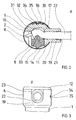
- FIG. 1 shows a housing provided with a cable bushing, in which a magnet coil, not shown, a pole pin and a permanent magnet are arranged.
- the housing consists of a cup-shaped housing part (1, 6), which has an enlarged area (6) towards its open side, and a closure part (11, 12).
- the cable duct serves to receive an electrical cable (2, 22), which consists of at least one core (2) and a sheath (22) surrounding the core (2).
- the electrical cable (2, 22) is used to connect an electrical component, such as the coil, arranged in the interior of the housing to an electrical device located outside the housing (1, 6, 11, 12).
- strain relief is required provided for the cable (2, 22).
- the strain relief essentially consists of two parts (11 and 14) which can be moved relative to one another for clamping the cable (2, 22).
- One part (11) of the strain relief is essentially formed as a cylindrical body, which is inserted with the major part of its axial extent in the enlarged area (6) of the cup-shaped housing part (1, 6).
- the protruding from the housing part (1, 6) part (12) of the part (11, 12) of the strain relief designed as a closure part is dimensioned in such a way that it rests on the edge region of the assembly opening of the housing part (1, 6) and its The peripheral surface is flush with the outer lateral surface of the enlarged area (6) of the housing part (1, 6).
- the part (11, 12) of the strain relief serving as a closure part has a projection (19) which extends essentially transversely to the longitudinal axis of the closure part (11, 12) and thus also essentially transversely to the longitudinal axis of the housing part (1, 6) the outer surface of the closure part (11, 12) is formed.
- a passage (9) for the cable (2, 22) is provided in the part (11, 12) of the strain relief serving as a closure part.
- the passage (9) is arranged essentially transversely to the longitudinal axis of the closure part (11, 12).
- the passage (9) is partly delimited by a web-like wall (7) which runs transversely to the longitudinal axis of the closure part (11, 12) and which has at its free end a deflection part (8) which has an outwardly curved surface.
- the passage (9) is followed by a further passage (20) for the cable (2, 22) arranged in the projection (19), which runs coaxially with the passage (9) provided in the closure part (11, 12).
- the passage (20) provided in the projection (19) and the passage (9) adjoining this in the closure part (11, 12) serve to receive the part of the cable (2, 22) having the sheath (22).
- recess (13) is arranged, which extends essentially from the outer surface of the closure part (11, 12) to the passage (9) and in this flows.
- a part designed as a clamping piece (14) is arranged in this recess (13) so that it can be moved towards or away from the cable (2, 22).
- the closure part (11, 12) and the clamping piece (14) together form the strain relief for the cable (2, 22).
- the clamping piece (14) is dimensioned in the direction of its longitudinal axis to be extended onto the cable (2, 22) (cable sheath 22) in such a way that after the insertion of the closure part (11) provided with the clamping piece (14) into the Pot-shaped housing part (1, 6) with its end facing away from the cable (2, 22), which in this exemplary embodiment has an outwardly extending projection (15), is supported on the inner wall of the housing part (6) and with it the cable (2 , 22) facing side with elastic deformation of the cable (2, 22) against a partial area of the wall delimiting the passage (9) for the cable (2, 22) or against a part connected to this wall, which is not shown here, presses.
- the two parts (11, 12 and 14) of the strain relief (11, 12, 14) are thus pretensioned essentially perpendicular to the wall of the cup-shaped housing part (1, 6) on the wall of the cup-shaped housing part (1, 6) .
- the recess (13) for the clamping piece (14) is arranged in the direction of the longitudinal axis of the closure part (11, 12) so that after the insertion of the closure part (11, 12) with the clamping piece into the housing part (1, 6) in the area (11) of the closure part (11, 12) surrounded by the housing part (1, 6).
- a U-shaped slot (23) is arranged in the wall of the pot-shaped housing part (1, 6) to accommodate the radially outwardly extending projection (19), as can be seen in FIG. 3.
- the slot (23) is arranged in the direction of the longitudinal axis of the pot-shaped housing part (1, 6) and is dimensioned such that it extends over the major part of the axial extent of the closure part (11, 12) and to the lid-like part ( 12) of the closure part (11, 12) pointing towards the edge of the cup-shaped housing part is open.
- the slot (23) and the projection (19) have, inter alia, the function of an anti-rotation device for the closure part (11, 12) relative to the cup-shaped housing part (1, 6).
- the passage (9) for the cable (2, 22) has a first stop for the end face of the jacket (22) of the cable (2, 22).
- the stop is composed of a step (10) and a surface of the deflection part (8) facing the end face of the jacket (22) of the cable (2, 22).
- the stop (10, 8) is arranged on the side of the passage (9) which is the free end of the passage leading out of the closure part (11, 12) (9) is opposite.
- the step (10) is sufficient as a stop if the deflection part (8) is omitted.
- a circumferential projection (17) which extends onto the jacket (22) of the cable (2, 22) and serves as a second stop.
- the circumferential projection (17) is designed in such a way that it allows the cable (2, 22) to be inserted into the passage (9) in the direction of the first stop (10) and allows the cable (2, 22) to move from the first However, stop (10) is prevented (barb principle).
- This arrangement of the stop (10) and of the circumferential projection (17) additionally fulfilling the function of a seal fixes the cable (2, 22) in the direction of its longitudinal axis. As can be seen from FIG.
- a recess (31) is provided on the side opposite the recess (13) for receiving the clamping piece (14) in the wall delimiting the passage (9), into which the cable (2, 22) is attached of the clamping piece (14) is pressed in, so that it takes a curved course in the passage (9) in this area.
- a projection (33) is provided on the side of the clamping piece (14) facing the cable (2, 22) in order to reinforce the curved deformation of the cable (2, 22), on the side of the clamping piece (14) facing the cable (2, 22) there is provided a projection (33) to be extended onto the cable (2, 22)
- Contact surface with the jacket of the cable has a contour that is adapted to the jacket surface of the cable (2, 22).
- the in the radially on the closure part (11, 12) arranged projection (19) provided passage (20) for the Cable (2, 22) serves as a guide for the cable (2, 22) and is designed in its free end area to widen outwards in the manner of a funnel (21), so that a slight pivoting movement of the cable (2, 22) is made possible without damaging the cable.
- a carrier (26) for a sealing device is provided on the side of the closure part (11, 12) facing the interior of the pot-shaped housing part (1, 6).
- the carrier (26) forms an integral unit with the closure part (11, 12).
- the sealing device serves to seal the interior of the housing with respect to the passage (9) for the cable (2, 22) and with respect to the mounting opening in the cup-shaped housing part (1, 6) for the closure part (11, 12).
- the sealing device is composed of a first sealing element and a second sealing element, which are supported on the carrier or are mounted in or on this.
- the first sealing element is designed as a disk-shaped seal (4) and is mounted in a part of the stepped recess (16, 25) in the larger diameter part of the support (26), which at the same time represents a partial area of the closure part (11, 12).
- the disc-shaped seal (4) has a passage (18) for the wire (2) of the cable (2, 22) or, in the case of a multi-core cable, a separate passage for each wire of the cable.
- the passage (18) for the wire is designed such that the wall delimiting the passage (18) or circumferential projections (3) arranged on this wall lie sealingly against the wire (2). With its peripheral surface or With circumferential projections (5) arranged on this peripheral surface, the disk-shaped seal (4) lies sealingly against the wall delimiting the recess (25) of the carrier (26).
- a circumferential groove (28) is provided in the outer lateral surface of the carrier (26), in which a sealing ring (27) serving as a second sealing element is arranged.
- the sealing ring (27) lies with its inside sealingly against the carrier (26) (in the groove 28) and with its outside sealing against the inside wall of the cup-shaped housing part (1,6).
- the first seal (4) designed as a wire seal thus seals the interior of the pot-shaped housing part (1, 6) against the passage (9) for the cable (2, 22) and against the strain relief (11, 12, 13, 14) located cavities.
- the sealing ring (27) serving as the second sealing element seals a possible gap between the inner wall of the pot-shaped housing part (1, 6) and the strain relief which simultaneously represents the closure part (11, 12) for this housing part (1, 6).
- the carrier for the sealing elements can, as mentioned above, be formed with the closure part as a one-piece structural unit, but it can also be formed as a separate part and arranged in the housing (1, 6) such that it is between the closure part and the electrical component area of the housing interior is located.
- the carrier or the support for the sealing element or for the sealing elements can be circular Have cross-section or a cross-section deviating from the circular shape, which is preferably adapted to the cross-sectional shape of the housing (1, 6).
- the clamping piece (14) cooperating with the closure part (11, 12) can have any shape.
- the recess provided in the closure part (11, 12) and used to receive the clamping piece (14) must always be so designed and dimensioned that the clamping piece (14) is securely guided in this recess.
- the projections (33 and 15) provided on the clamping piece (14) can be dispensed with.
- the clamping piece (14) is dimensioned in the direction of its axis to be extended on the cable (22, 2) so that it is so far into the passage (9) for the cable when the strain relief is installed in the housing (2, 22) that the cable (2, 22) is securely held by the clamping piece (14) and the wall of the recess of the part (11, 12) of the strain relief serving as a closure part opposite the clamping piece (14).
- a recess (34) is provided in the outer circumferential surface of the closure part (11, 12) into which a nose-like projection (35) of the housing wall produced by embossing or indentation engages (see Fig. 2 and Fig. 3).
- a plate (32) provided with a recess (36) which is mounted in a recess (30) in the lateral surface of the closure part (11, 12) is.
- the nose-like projection (35) extends through the recess (36) of the plate (32).
- the plate (32) serves to stiffen the area of the closure part (11, 12) receiving the nose-like projection (35) and additionally prevents deformation of the housing wall in the area having the nose-like projection (35) during the embossing process.
- the cable duct can of course also be designed so that the cable (2, 22) is led out of the housing (1, 6) in the direction of the longitudinal axis of the housing (1, 6) and the closure part (11, 12).
- the deflection part (8) for the wires (2) of the cable (2, 22) can be dispensed with.
- the cable entry is installed as described below.
- the cable (2, 22) is inserted through the passage (20) of the projection (19) and through the passage (9) of the closure part (11, 12) into the closure part (11, 12) until the End face of the cable sheath (22) comes to rest on the projection serving as a stop (10). Then the wires (2) of the cable (2, 22) are placed around the deflection part (8) and passed through the stepped recess (16, 25, 24) of the carrier (26) for the sealing elements (4 and 27).
- the first sealing element (4) designed as a wire seal is pushed onto the wire (2) or onto the wires (2) of the cable (2, 22) until the first sealing element (4) into the stepped recess (16, 25 , 24) of the carrier (26) is immersed and with its closing part (11, 12) End face on the surface (24) of the stepped recess (16, 25, 24) comes to rest.
- the second sealing element (27) designed as a sealing ring, was inserted into the groove (28) in the outer lateral surface of the carrier (26).
- the clamping piece (14) is inserted into the recess (13) of the closure part (11, 12) and pressed into it until the projection (15) of the clamping piece (14) is approximately flush with the adjacent area of the lateral surface of the closure part (11, 12) completes. Then the closure part (11, 12) with the clamping piece (14) towards the bottom (29) of the housing is pushed into the housing (1, 6). The lid-like part (12) of the closure part (11, 12) is placed on the edge of the housing (1, 6).
- the nose-like projection (35) of the housing wall is produced, which engages in the recess (34) in the outer surface of the closure part (11, 12).
Landscapes
- Engineering & Computer Science (AREA)
- Architecture (AREA)
- Civil Engineering (AREA)
- Structural Engineering (AREA)
- Installation Of Indoor Wiring (AREA)
- Details Of Connecting Devices For Male And Female Coupling (AREA)
- Insertion, Bundling And Securing Of Wires For Electric Apparatuses (AREA)
Claims (17)
- Traversée de câble pour un boîtier contenant au moins un composant électrique, notamment pour un capteur d'impulsions de comptage de tours, présentant les caractéristiques suivantes :a) le boîtier est constitué par une partie boîtier (1, 6) aménagée en forme de pot et par une partie obturatrice (11, 12) pour fermer la partie boîtier en forme de pot (1, 6);b) pour relier le composant électrique situé dans le boîtier (1, 6, 11, 12) à un appareil électrique situé à l'extérieur du boîtier (1, 6, 11, 12), un câble électrique (2, 22) est utilisé et sort du boîtier (1, 6, 11, 12);c) des moyens de décharge de traction sont prévus pour le câble;
caractérisée par les caractéristiques suivantes :d) les moyens de décharge de traction présentent deux parties mobiles l'une par rapport à l'autre (11, 12 et 14), pour le serrage-coincement du câble (2, 22);e) les deux parties (11, 12 et 14) des moyens de décharge de traction s'appuient, sous précontrainte, sensiblement perpendiculairement à la paroi de la partie boîtier (1, 6) en forme de pot, contre la paroi de cette partie boîtier (1, 6) en forme de pot;f) la partie obturatrice (11, 12) pour obturer la partie boîtier (1, 6) en forme de pot est constituée par au moins la première des deux parties (11, 12 et 14) des moyens de décharge de traction. - Traversée de câble selon revendication 1, caractérisée par le fait que le câble (2, 22) sort radialement du boîtier.
- Traversée de câble selon revendication 1, caractérisée par le fait que le câble (2, 22) sort du boîtier en s'étendant en direction de l'axe longitudinal du boîtier (1, 6, 11, 12).
- Traversée de câble selon au moins l'une des revendications précédentes, caractérisée par les caractéristiques suivantes :a) la première partie des moyens de décharge de traction, servant de partie obturatrice (11, 12), est réalisée de manière à pouvoir être introduite dans la partie boîtier en forme de pot (1, 6) par au moins une région partielle (11) de son étendue axiale;b) pour la sortie du câble (2, 22) hors du boîtier (1, 6, 11), il est prévu, dans la partie obturatrice (11, 12), un passage (9) pour le câble (2, 22);c) la partie obturatrice (11, 12) présente un évidement (13) qui s'étend sensiblement transversalement à l'axe longitudinal du passage (9) pour le câble (2, 22) et qui s'étend sensiblement de la surface périphérique extérieure de la partie obturatrice (11, 12) jusqu'au passage (9) et débouche dans celui-ci;d) l'autre partie (14) des moyens de décharge de traction sert de pièce de serrage et est introduite, en direction du câble (2, 22), dans l'évidement (13) de la partie obturatrice (11, 12);e) la pièce de serrage (14) et l'évidement (13) sont réalisés de manière que la pièce de serrage (14) soit guidée dans la partie obturatrice (11, 12) par au moins une région partielle de la paroi bordant l'évidement (13);f) la pièce de serrage (14) est dimensionnée, dans la direction de son axe longitudinal s'étendant vers le câble (2, 22), de manière qu'après l'introduction de la partie obturatrice (11, 12) dans le boîtier (1, 6), elle s'appuie, par son extrémité éloignée du câble (2, 22), contre la paroi intérieure de la partie boîtier (1, 6) en forme de pot, et, par son côté tourné vers le câble (2, 22) appuie ce câble (2, 22) en le déformant élastiquement, contre une région partielle de la paroi bordant le passage (13) pour le câble (2, 22), ou contre une pièce ou partie liée à cette paroi;g) l'évidement (13) pour recevoir la pièce de serrage (14) est disposé, quand on le considère en direction de l'axe longitudinal de la partie obturatrice (11, 12), de manière telle qu'après l'introduction de la partie obturatrice (11, 12) dans la partie boîtier en forme de pot (1, 6), il se trouve dans la région de la partie obturatrice (11, 12) entourée par cette partie boîtier (1, 6);h) la pièce de serrage (14), l'évidement (13) pour recevoir la pièce de serrage (14) ainsi qu'une région partielle de la paroi de la partie obturatrice (11, 12) bordant le passage (9) pour le câble (2, 22), forment les moyens de décharge de traction (11, 12, 14) pour le câble (2, 22).
- Traversée de câble selon au moins l'une des revendications précédentes, caractérisée par les caractéristiques suivantes :a) en son côté tourné vers le volume intérieur de la partie boîtier en forme de pot (1, 6), la partie obturatrice (11, 12) est reliée à un support (26) pour au moins un dispositif d'étanchéité, afin d'étancher le volume intérieur de la partie boîtier en forme de pot (1, 6) à l'égard du passage (9) pour le câble (2, 22), ainsi qu'à l'égard de l'évidement (13) pour la pièce de serrage (14);b) le dispositif d'étanchéité est réalisé et disposé de manière à s'appliquer avec étanchéité d'un côté contre le brin (2) du câble (2, 22) et de l'autre côté, avec étanchéité, contre le support (26) et/ou contre la paroi intérieure de la partie boîtier en forme de pot (1, 6).
- Traversée de câble selon au moins l'une des revendications précédentes, caractérisée par le fait que la partie obturatrice (11, 12) présente un saillant (19) avec, s'étendant en direction de l'axe longitudinal du saillant (19), un autre passage (20) pour le câble (2, 22), lequel passage se raccorde au passage (9) aménagé dans la partie obturatrice (11, 12).
- Traversée de câble selon au moins l'une des revendications précédentes, caractérisée par les caractéristiques suivantes :a) le passage (9) pour le câble (2, 22), ce passage étant aménagé dans la partie obturatrice (11, 12), présente une partie en gradin (10) réalisée en tant que butée pour la surface en bout d'une gaine (22) entourant le câble (2, 22);b) la butée (10) est disposée du côté du passage (9) qui est en vis-à-vis de l'extrémité libre du passage (9) sortant de la partie obturatrice (11, 12).
- Traversée de câble selon au moins l'une des revendications précédentes, caractérisée par les caractéristiques suivantes :a) du côté à l'opposé de la butée (10), il est prévu, dans la paroi bordant le passage (9), un saillant (17) entourant qui s'étend vers la gaine (22) du câble (2, 22);b) le saillant entourant (17) est réalisé de manière à permettre une introduction du câble (2, 22) dans le passage (9), en direction de la butée (10), mais de manière à empêcher tout mouvement du câble (2, 22) dans le sens de son éloignement de la butée (10).
- Traversée de câble selon au moins l'une des revendications précédentes, caractérisée par le fait qu'en son côté tourné vers le câble (2, 22), la pièce de serrage (14) présente au moins un saillant (33) s'étendant en direction du câble (2, 22).
- Traversée de câble selon au moins l'une des revendications précédentes, caractérisée par le fait que la paroi qui, dans la partie obturatrice (11, 12), borde la passage (9) pour le câble (2, 22), présente une dépression (31) qui est située du côté du passage (9) opposé à l'évidement (13) pour la pièce de serrage (14).
- Traversée de câble selon au moins l'une des revendications précédentes, caractérisée par les caractéristiques suivantes :a) dans la paroi de la partie boîtier en forme de pot (1, 6) est disposée une fente (23) s'étendant en direction de l'axe longitudinal de la partie boîtier en forme de pot (1, 6);b) la fente (23) s'étend sur la majeure partie de l'étendue axiale de la partie obturatrice (11, 12) et est ouverte en direction du bord de la partie boîtier en forme de pot (1, 6) en regard de la partie obturatrice (11, 12);c) la fente (23) sert à recevoir le saillant (19) disposé sur la partie obturatrice (11, 12) et sert d'arrêt en rotation pour la partie obturatrice (11, 12).
- Traversée de câble selon au moins l'une des revendications précédentes, caractérisée par les caractéristiques suivantes :a) le support (26) pour le dispositif d'étanchéité (4, 27) est constitué par un relief ou saillant de la partie obturatrice (11, 12);b) le saillant est disposé sur le côté de la partie obturatrice (11, 12) tourné vers le volume intérieur de la partie boîtier en forme de pot (1, 6), et s'étend en direction du volume intérieur de la partie boîtier en forme de pot (1, 6).
- Traversée de câble selon revendication 12, caractérisée par le fait que le relief est réalisé sous la forme d'un corps annulaire.
- Traversée de câble selon au moins l'une des revendications précédentes, caractérisée par le fait que le support pour le dispositif d'étanchéité est réalisé sous la forme d'une pièce séparée, autonome, qui prend appui contre une partie de la partie boîtier en forme de pot (1, 6).
- Traversée de câble selon au moins l'une des revendications précédentes, caractérisée par les caractéristiques suivantes :a) le dispositif d'étanchéité se compose d'un premier élément d'étanchéité (4) et d'un deuxième élément d'étanchéité (27);b) le premier élément d'étanchéité (4) est réalisé sous la forme d'un corps en forme de disque ou tranche, et le deuxième élément d'étanchéité (27) est réalisé sous la forme d'un corps annulaire;c) le premier élément d'étanchéité (4) est disposé dans l'espace bordé par le saillant (26) et s'applique, par sa surface périphérique, ou par des reliefs entourants (5) agencés sur sa surface périphérique, de manière étanche contre la paroi du saillant (26);d) le premier élément d'étanchéité (4) présente au moins un passage (18) pour le ou les brin(s) (2) du câble (2, 22), ce ou ces passage(s) étant réalisé(s) et agencé(s), de manière que la ou les paroi(s) bordant le ou les passage(s) (18) s'appliquent avec étanchéité contre le ou les brin(s) du câble (2, 22);e) le deuxième élément d'étanchéité (27) est monté sur ou dans la surface périphérique extérieure du relief (26) et s'applique, par son côté intérieur, avec étanchéité, contre la surface périphérique ou dans une rainure (28) aménagée dans la surface périphérique du saillant (26) et s'applique, par son côté extérieur, avec étanchéité, contre le côté intérieur du boîtier (1, 6).
- Traversée de câble selon au moins l'une des revendications précédentes, caractérisée par les caractéristiques suivantes :a) au moins une dépression (34) est prévue dans la surface périphérique extérieure de la partie obturatrice (11, 12);b) la paroi du boîtier (1, 6) présente un saillant ou relief (35) s'étendant en direction de la surface périphérique extérieure de la partie obturatrice (11, 12), lequel pénètre dans la dépression (34) de la partie obturatrice (11, 12).
- Traversée de câble selon revendication 16, caractérisée par le fait que, dans la région de la dépression (34) de la partie obturatrice (11, 12) est agencée une pièce du genre plaque (32) qui est située dans un évidement de la partie obturatrice (11, 12), entre la surface périphérique extérieure de la partie obturatrice (11, 12) et la paroi intérieure du boîtier (1, 6), ladite partie du genre plaque (32) présentant un passage (36) pour le saillant (35) du genre nez que comporte la paroi de la partie boîtier en forme de pot (1, 6).
Applications Claiming Priority (2)
| Application Number | Priority Date | Filing Date | Title |
|---|---|---|---|
| DE3820378A DE3820378A1 (de) | 1988-06-15 | 1988-06-15 | Kabeldurchfuehrung |
| DE3820378 | 1988-06-15 |
Publications (3)
| Publication Number | Publication Date |
|---|---|
| EP0346587A2 EP0346587A2 (fr) | 1989-12-20 |
| EP0346587A3 EP0346587A3 (fr) | 1991-12-11 |
| EP0346587B1 true EP0346587B1 (fr) | 1994-01-12 |
Family
ID=6356616
Family Applications (1)
| Application Number | Title | Priority Date | Filing Date |
|---|---|---|---|
| EP89106723A Expired - Lifetime EP0346587B1 (fr) | 1988-06-15 | 1989-04-14 | Traversée de câble |
Country Status (3)
| Country | Link |
|---|---|
| US (1) | US5064967A (fr) |
| EP (1) | EP0346587B1 (fr) |
| DE (2) | DE3820378A1 (fr) |
Cited By (1)
| Publication number | Priority date | Publication date | Assignee | Title |
|---|---|---|---|---|
| WO2023208624A1 (fr) * | 2022-04-27 | 2023-11-02 | eltherm production GmbH | Dispositif de montage avec unité de soulagement de traction |
Families Citing this family (12)
| Publication number | Priority date | Publication date | Assignee | Title |
|---|---|---|---|---|
| US5828364A (en) | 1995-01-03 | 1998-10-27 | Microsoft Corporation | One-piece case top and integrated switch for a computer pointing device |
| US5616048A (en) * | 1995-06-26 | 1997-04-01 | The Whitaker Corporation | Electrical connector with electrical contact and strain relief |
| US5695358A (en) * | 1995-06-27 | 1997-12-09 | The Whitaker Corporation | Electrical connector with strain relief for a bundle of wires |
| USD392942S (en) | 1996-08-15 | 1998-03-31 | Monster Cable Internationa, Ltd. | Cable assembly with pod housing |
| US5744754A (en) * | 1997-03-05 | 1998-04-28 | Hubbell Incorporated | Electrical receptacle incorporating integral electrical wire strain relief arrangement |
| USD445796S1 (en) | 1999-08-31 | 2001-07-31 | Iomega Corporation | Cable strain-relief member for a PC card |
| SE531217C2 (sv) * | 2007-05-29 | 2009-01-20 | Roxtec Ab | Kabelgenomföring |
| JP5650509B2 (ja) * | 2010-11-29 | 2015-01-07 | キヤノン株式会社 | 放射線用カセッテキャリア及び可搬型放射線撮影装置 |
| WO2015063928A1 (fr) * | 2013-10-31 | 2015-05-07 | 矢崎総業株式会社 | Connecteur étanche à l'eau |
| CN105281281B (zh) * | 2015-11-18 | 2017-07-28 | 湖南菲尔斯特传感器有限公司 | 一种尿素传感器出线密封结构 |
| EP3989786B1 (fr) * | 2019-06-25 | 2024-07-31 | Breville Pty Limited | Appareil sous vide |
| DE102022112290A1 (de) | 2022-04-27 | 2023-11-02 | eltherm production GmbH | Montagevorrichtung mit Zugentlastungseinrichtung |
Family Cites Families (12)
| Publication number | Priority date | Publication date | Assignee | Title |
|---|---|---|---|---|
| US2590886A (en) * | 1948-04-08 | 1952-04-01 | Pedersen Svend Laessphie | Strain relief for electrical connectors |
| DE806686C (de) * | 1949-05-11 | 1951-06-18 | Schanzenbach & Co G M B H G | Leitungseinfuehrung mit Stopfbuchse und Zugentlastung |
| US3252024A (en) * | 1963-08-13 | 1966-05-17 | Bendix Corp | Electric pulse generating means |
| DE7105475U (de) * | 1971-02-13 | 1971-07-29 | Hellige F & Co Gmbh | Vorrichtung zur Kabel Zugentlastung |
| GB2068176A (en) * | 1979-12-05 | 1981-08-05 | Golden Town Enterprises Co Ltd | Strain relief in lamp holders |
| DE3032249A1 (de) * | 1980-08-27 | 1982-04-01 | Jean Müller KG Elektrotechnische Fabrik, 6228 Eltville | Einrichtung fuer loesbare zuleitungs-anbringung |
| DE3108085C2 (de) * | 1981-03-04 | 1984-05-03 | Karl 7298 Loßburg Hehl | Winkelzugentlastungsvorrichtung zur Einführung elektrischer Versorgungsleitungen in ein Gerät |
| DE3151702A1 (de) * | 1981-12-29 | 1983-07-07 | Heinrich Kopp Gmbh & Co Kg, 8756 Kahl | Elektrischer (schutzkontakt-) stecker mit kabel-knickschutz- und zugentlastungseinrichtung |
| DE3208108A1 (de) * | 1982-03-06 | 1983-09-08 | Robert Bosch Gmbh, 7000 Stuttgart | Elektrischer anschluss fuer elektrisches aggregat |
| DE3530288A1 (de) * | 1985-08-24 | 1987-03-05 | Bosch Gmbh Robert | Induktiver signalgeber |
| DE3544197A1 (de) * | 1985-12-13 | 1987-06-19 | Siemens Ag | Leitungseinfuehrung |
| DE3700102A1 (de) * | 1987-01-03 | 1988-07-14 | Kallabis Manfred | Schaft einer gelenk-endoprothese |
-
1988
- 1988-06-15 DE DE3820378A patent/DE3820378A1/de not_active Withdrawn
-
1989
- 1989-04-14 DE DE89106723T patent/DE58906669D1/de not_active Expired - Fee Related
- 1989-04-14 EP EP89106723A patent/EP0346587B1/fr not_active Expired - Lifetime
- 1989-05-26 US US07/358,026 patent/US5064967A/en not_active Expired - Lifetime
Cited By (1)
| Publication number | Priority date | Publication date | Assignee | Title |
|---|---|---|---|---|
| WO2023208624A1 (fr) * | 2022-04-27 | 2023-11-02 | eltherm production GmbH | Dispositif de montage avec unité de soulagement de traction |
Also Published As
| Publication number | Publication date |
|---|---|
| DE3820378A1 (de) | 1989-12-21 |
| EP0346587A2 (fr) | 1989-12-20 |
| EP0346587A3 (fr) | 1991-12-11 |
| US5064967A (en) | 1991-11-12 |
| DE58906669D1 (de) | 1994-02-24 |
Similar Documents
| Publication | Publication Date | Title |
|---|---|---|
| DE3625999C2 (fr) | ||
| DE19608675C2 (de) | Temperaturmeßvorrichtung mit einer medienführenden Rohrleitung | |
| EP1123574B1 (fr) | Attache de cable | |
| EP1022836A2 (fr) | Presse-étoupe | |
| DE19824808C1 (de) | Halterung für längliche Körper mit elektrischer Abschirmung | |
| EP0527368B1 (fr) | Dispositif pour traversée de câble | |
| EP0346587A2 (fr) | Traversée de câble | |
| DE9214719U1 (de) | Geschirmter Stecker mit Kabelanschluß | |
| DE3110660C2 (de) | Garnitur für das Ende eines Mittelspannnungs- oder Hochspannunskabels | |
| DE102008019165A1 (de) | Kabelverschraubung, insbesondere für ein Abschirm- oder Erdungskabel | |
| DE4339914C2 (de) | Wasserdichter Steckverbinder | |
| EP0141423B1 (fr) | Moyens pour atténuer l'effort de tension sur un câble | |
| WO1991010270A1 (fr) | Dispositif de serrage pour la fabrication d'un raccordement electrique | |
| DE4300243C1 (de) | Koaxialer 7/16-Buchsensteckverbinder | |
| CH689683A5 (de) | Gehaeuse mit einer Vorrichtung zur Kabelzugentlastung. | |
| EP0415136B1 (fr) | Insert pour connecteur à boîtier métallique | |
| EP0318007B1 (fr) | Dispositif de connexion par serrage pour établir un branchement au conducteur d'un câble sous tension | |
| EP1590860A1 (fr) | Dispositif de raccordement par serrage servant a raccorder une cosse annulaire et appareil electrique associe | |
| DE9100004U1 (de) | Kabeldurchführung | |
| DE69405432T2 (de) | Zündkerzenkappenvorrichtung für Verbrennungsmotor | |
| EP0957539A2 (fr) | Connecteurs électriques | |
| DE4331969C2 (de) | Induktiver Geschwindigkeitssensor | |
| EP0974172B1 (fr) | Dispositif pour la fixation de lignes electriques | |
| DE4022678C2 (de) | Zugentlastetes Kabel mit einem Steckverbinder | |
| EP1032083A2 (fr) | Serre-câble pour le maintien mécanique et la connexion électrique d'un câble |
Legal Events
| Date | Code | Title | Description |
|---|---|---|---|
| PUAI | Public reference made under article 153(3) epc to a published international application that has entered the european phase |
Free format text: ORIGINAL CODE: 0009012 |
|
| AK | Designated contracting states |
Kind code of ref document: A2 Designated state(s): DE FR GB SE |
|
| PUAL | Search report despatched |
Free format text: ORIGINAL CODE: 0009013 |
|
| AK | Designated contracting states |
Kind code of ref document: A3 Designated state(s): DE FR GB SE |
|
| 17P | Request for examination filed |
Effective date: 19911106 |
|
| 17Q | First examination report despatched |
Effective date: 19930201 |
|
| RAP1 | Party data changed (applicant data changed or rights of an application transferred) |
Owner name: WABCO VERMOEGENSVERWALTUNGS-GMBH |
|
| GRAA | (expected) grant |
Free format text: ORIGINAL CODE: 0009210 |
|
| AK | Designated contracting states |
Kind code of ref document: B1 Designated state(s): DE FR GB SE |
|
| REF | Corresponds to: |
Ref document number: 58906669 Country of ref document: DE Date of ref document: 19940224 |
|
| GBT | Gb: translation of ep patent filed (gb section 77(6)(a)/1977) |
Effective date: 19940419 |
|
| ET | Fr: translation filed | ||
| PLBE | No opposition filed within time limit |
Free format text: ORIGINAL CODE: 0009261 |
|
| STAA | Information on the status of an ep patent application or granted ep patent |
Free format text: STATUS: NO OPPOSITION FILED WITHIN TIME LIMIT |
|
| 26N | No opposition filed | ||
| EAL | Se: european patent in force in sweden |
Ref document number: 89106723.3 |
|
| PGFP | Annual fee paid to national office [announced via postgrant information from national office to epo] |
Ref country code: GB Payment date: 19970407 Year of fee payment: 9 |
|
| PGFP | Annual fee paid to national office [announced via postgrant information from national office to epo] |
Ref country code: SE Payment date: 19970415 Year of fee payment: 9 |
|
| PGFP | Annual fee paid to national office [announced via postgrant information from national office to epo] |
Ref country code: FR Payment date: 19970430 Year of fee payment: 9 |
|
| PG25 | Lapsed in a contracting state [announced via postgrant information from national office to epo] |
Ref country code: GB Free format text: LAPSE BECAUSE OF NON-PAYMENT OF DUE FEES Effective date: 19980414 |
|
| PG25 | Lapsed in a contracting state [announced via postgrant information from national office to epo] |
Ref country code: SE Free format text: LAPSE BECAUSE OF NON-PAYMENT OF DUE FEES Effective date: 19980415 |
|
| PG25 | Lapsed in a contracting state [announced via postgrant information from national office to epo] |
Ref country code: FR Free format text: THE PATENT HAS BEEN ANNULLED BY A DECISION OF A NATIONAL AUTHORITY Effective date: 19980430 |
|
| GBPC | Gb: european patent ceased through non-payment of renewal fee |
Effective date: 19980414 |
|
| EUG | Se: european patent has lapsed |
Ref document number: 89106723.3 |
|
| REG | Reference to a national code |
Ref country code: FR Ref legal event code: ST |
|
| PGFP | Annual fee paid to national office [announced via postgrant information from national office to epo] |
Ref country code: DE Payment date: 20010417 Year of fee payment: 13 |
|
| PG25 | Lapsed in a contracting state [announced via postgrant information from national office to epo] |
Ref country code: DE Free format text: LAPSE BECAUSE OF NON-PAYMENT OF DUE FEES Effective date: 20021101 |