EP0346584A2 - Rectifieuse cylindrique sans centre - Google Patents
Rectifieuse cylindrique sans centre Download PDFInfo
- Publication number
- EP0346584A2 EP0346584A2 EP89106553A EP89106553A EP0346584A2 EP 0346584 A2 EP0346584 A2 EP 0346584A2 EP 89106553 A EP89106553 A EP 89106553A EP 89106553 A EP89106553 A EP 89106553A EP 0346584 A2 EP0346584 A2 EP 0346584A2
- Authority
- EP
- European Patent Office
- Prior art keywords
- regulating
- grinding
- shaft
- wheel shaft
- wheels
- Prior art date
- Legal status (The legal status is an assumption and is not a legal conclusion. Google has not performed a legal analysis and makes no representation as to the accuracy of the status listed.)
- Withdrawn
Links
Images
Classifications
-
- B—PERFORMING OPERATIONS; TRANSPORTING
- B24—GRINDING; POLISHING
- B24B—MACHINES, DEVICES, OR PROCESSES FOR GRINDING OR POLISHING; DRESSING OR CONDITIONING OF ABRADING SURFACES; FEEDING OF GRINDING, POLISHING, OR LAPPING AGENTS
- B24B5/00—Machines or devices designed for grinding surfaces of revolution on work, including those which also grind adjacent plane surfaces; Accessories therefor
- B24B5/18—Machines or devices designed for grinding surfaces of revolution on work, including those which also grind adjacent plane surfaces; Accessories therefor involving centreless means for supporting, guiding, floating or rotating work
Definitions
- the invention relates to a centerless cylindrical grinding machine for the simultaneous plunge grinding of several workpieces, with two grinding wheels rigidly received on a driven grinding wheel shaft at an axial distance from one another and two associated regulating wheels which are frusto-conical on the circumference and which are rigidly fastened on a driven control wheel shaft, which are approximately parallel to the grinding wheel shaft, but is arranged adjustable in its angular position relative to this.
- This correction is carried out in the known centerless cylindrical grinding machines for machining two workpieces in that the angular position of the regulating wheel shaft arranged approximately parallel to the grinding wheel shaft is adjusted.
- the regulating wheel shaft is approximated by one between the two
- the regulating disc lying pivot point is adjusted by a small angular amount by means of an adjusting device.
- This adjustment takes place as a function of the diameters measured on both workpieces by such an angular amount that the same diameters of the workpieces are again achieved in the subsequent machining.
- This adjustment movement is superimposed on the infeed movement of the regulating wheel shaft directed transversely to the axis of the grinding wheel shaft. Since only two workpieces can be machined at a time, the working capacity of this cylindrical grinding machine is limited.
- the object of the invention is therefore to design a centerless cylindrical grinding machine of the type mentioned in the introduction in such a way that at least three workpieces can be machined on it simultaneously in the plunge-cut grinding process.
- At least one middle grinding wheel is rigidly received on the grinding wheel shaft between the two grinding wheels and that the middle grinding wheel is assigned a middle regulating wheel arranged between the two rigidly fastened regulating wheels, which is rotatably and axially adjustable on the Control wheel shaft is attached to the hub.
- the middle regulating disc can be adjusted axially relative to the two rigidly arranged regulating discs. Since it - like the other regulating disks - has a frustoconical shape, its effective diameter changes with its axial displacement compared to the workpiece, which is guided in an axially fixed position and therefore in a constant orientation to the assigned plunge-cut grinding wheel. During the infeed correction of the two outer regulating discs rigidly held on the regulating disc shaft by means of the angle adjustment of the regulating wheel shaft compared to the grinding wheel shaft, the effective diameter of the middle regulating wheel is changed by its axial adjustment. Both adjustments are made depending on the actual work piece diameters achieved in a simultaneous plunge grinding process.
- the hub carrying the central regulating disc is connected via at least one driver to a push rod which is axially displaceable in a longitudinal bore of the regulating disc shaft and which is connected to an adjusting device at one end of the regulating disc shaft. It is thereby achieved that the adjustment of the central regulating disk can be carried out by means of an adjustment device which is easily accessible from the outside at the end of the regulating disk shaft and which is, for example, a micrometer screw.
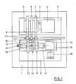
- the centerless cylindrical grinding machine which is only indicated schematically in FIG. 1, has a grinding carriage 2 on a machine bed 1, on which a grinding wheel shaft 3 with its drive device 4 is mounted.
- the grinding wheel shaft 3 carries three rigidly mounted grinding wheels 5, 6 and 7 at an axial distance from one another, which are designed on their circumference in accordance with the outer contour of the workpieces 8 to be ground.
- a regulating disc shaft 11 with the regulating disc drive 12 is mounted on a swivel support 10.
- the regulating wheel shaft 11 carries three regulating wheels 13, 14 and 15 at an axial distance from one another.
- the regulating wheels 13, 14 and 15 are frustoconical in shape and guide the workpieces 8 during the grinding process.
- the distance between each regulating wheel 13, 14 and 15 and the respectively assigned one The grinding wheel 5, 6 and 7 determines the actual size of the machined workpiece 8.
- the workpieces 8 lie on a workpiece support 16 during machining and are axially pressed against an assigned workpiece stop 17.
- the support 10 carrying the regulating disk shaft 1 can be pivoted about a pivot point 19 by means of an adjusting device 18, which is only indicated schematically in FIG. 1. This changes the relative position of the two outer regulating disks 13 and 15 to the respectively assigned outer grinding disks 5 and 7, as a result of which the actual diameter of the outer workpieces 8 also changes.
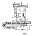
- the central regulating disk 14 is attached to a hub 20, which is supported on the spherical cage 21 by the regulating disk shaft 11 in an axially displaceable manner.
- the two outer ones Regulating disks 13 and 15 are each attached to hubs 22 and 23, which are rigidly connected to the regulating disk shaft 11 by means of clamping rings 24.
- the hub 20 of the central regulating disk 14 is connected to the regulating disk shaft 11 so that it cannot rotate, but is axially displaceable.
- a push rod 28 is axially displaceable by a small amount.
- a radially extending driver pin 29 connected to the push rod 28 protrudes on both sides through bores 30 from the regulating disk shaft 11 and is connected to the hub 20.
- a helical compression spring 31 supported at the end of the longitudinal bore 27 is supported on the push rod 28 and, together with the hub 20 connected to it, tries to push it towards the end (left in FIG. 2) of the regulating disk shaft 11 from which the push rod 28 protrudes.
- the push rod 28 is connected at its end protruding from the regulating disk shaft 11 to a micrometer screw 32, which forms an axial adjustment device for the push rod 28. If the push rod 28 is axially displaced by means of the micrometer screw 27 against the force of the spring 31, the hub 20 and the central regulating disk 14 attached to it are also axially displaced. As a result of the truncated cone shape of the regulating disk 14, its effective diameter changes, that is to say the effective distance from the assigned central one Grinding wheel 6, so that the actual diameter of the middle workpiece 8 that results during plunge grinding also changes. In this way, regardless of the changes in diameter of the two outer workpieces 8 achieved, a change in diameter of the respective middle workpiece 8 is also achieved.
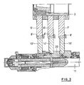
- FIG. 3 is structurally essentially the same as the embodiment according to FIG. 2, so that the same reference numerals are used.
- the workpieces 8 'to be machined here do not have a spherical but a cylindrical outer contour to be machined. Therefore, both the grinding wheels 5 ', 6' and 7 'as well as the respective control wheels 13', 14 'and 15' are designed on their circumference with the same cone angle, but in the opposite direction, frustoconical.
Landscapes
- Engineering & Computer Science (AREA)
- Mechanical Engineering (AREA)
- Grinding Of Cylindrical And Plane Surfaces (AREA)
Applications Claiming Priority (2)
| Application Number | Priority Date | Filing Date | Title |
|---|---|---|---|
| DE3820041 | 1988-06-13 | ||
| DE19883820041 DE3820041A1 (de) | 1988-06-13 | 1988-06-13 | Spitzenlose rundschleifmaschine |
Publications (2)
| Publication Number | Publication Date |
|---|---|
| EP0346584A2 true EP0346584A2 (fr) | 1989-12-20 |
| EP0346584A3 EP0346584A3 (fr) | 1990-07-11 |
Family
ID=6356422
Family Applications (1)
| Application Number | Title | Priority Date | Filing Date |
|---|---|---|---|
| EP89106553A Withdrawn EP0346584A3 (fr) | 1988-06-13 | 1989-04-13 | Rectifieuse cylindrique sans centre |
Country Status (2)
| Country | Link |
|---|---|
| EP (1) | EP0346584A3 (fr) |
| DE (1) | DE3820041A1 (fr) |
Family Cites Families (2)
| Publication number | Priority date | Publication date | Assignee | Title |
|---|---|---|---|---|
| US2017875A (en) * | 1932-12-05 | 1935-10-22 | Frederick J Theler | Lapping machine |
| DE801500C (de) * | 1949-01-30 | 1951-01-08 | Herminghausen Werke G M B H | Vorrichtung zum gleichzeitigen Bearbeiten zweier seitlicher Schleif-stellen an auf spitzenlosen Rundschleifmaschinen unter Verwendung zweier Schleifscheiben zu schleifenden Werkstuecken |
-
1988
- 1988-06-13 DE DE19883820041 patent/DE3820041A1/de not_active Withdrawn
-
1989
- 1989-04-13 EP EP89106553A patent/EP0346584A3/fr not_active Withdrawn
Also Published As
| Publication number | Publication date |
|---|---|
| EP0346584A3 (fr) | 1990-07-11 |
| DE3820041A1 (de) | 1989-12-21 |
Similar Documents
| Publication | Publication Date | Title |
|---|---|---|
| DE3435313C2 (de) | Vorrichtung zum Außenrundschleifen | |
| DE10234707A1 (de) | Verfahren und Vorrichtung zum Schleifen eines rotationssymmetrischen Maschinenbauteils | |
| DE102010010758A1 (de) | Spitzenlose Rundschleifmaschine zum Schleifen von stangenförmigen Werkstücken und Verfahren zum spitzenlosen Rundschleifen von stangenförmigen Werkstücken | |
| DE2824073C2 (de) | Spitzenlose Schleifmaschine | |
| DE6902724U (de) | Schleifmaschine zum praezisionsschleifen eines werkzeuges. | |
| DE1933575B2 (de) | Vorrichtung zum Ziehschleifen von Außen- oder Innenflächen von Werkstücken | |
| CH663923A5 (de) | Abrichteinrichtung fuer bahngesteuertes abrichten von schleifscheibenprofilen. | |
| DE1300834B (de) | Einrichtung zum Honen zylindrischer Werkstuecke | |
| DE2718731C2 (de) | Außenrundschleifmaschine | |
| DE2712029C3 (de) | Nockenschleifmaschine | |
| DE2243884A1 (de) | Vorrichtung zum abrichten von schleifscheiben | |
| EP0346584A2 (fr) | Rectifieuse cylindrique sans centre | |
| DE2335575B2 (fr) | ||
| DE4012658C2 (de) | Brillenglasrandschleifmaschine | |
| DE69706974T3 (de) | Schleifmaschine | |
| DE4025745C2 (fr) | ||
| EP0425924A1 (fr) | Laminoir à profilés pour la manufacture de profilés en forme de cylindre creux ou godet en tôle | |
| DE4011715C1 (fr) | ||
| EP0176654B1 (fr) | Procédé et dispositif pour rectifier à grande vitesse des profils de pièces à symétrie de révolution | |
| DE1502492B1 (de) | Kopierschleifmaschine | |
| EP0045433A1 (fr) | Machine à meuler ou à polir comprenant une broche porte-outil entraînée d'un mouvement axial oscillant et d'un mouvement rotatif | |
| DE2453885A1 (de) | Verfahren und vorrichtung zur herstellung von kurvenscheiben | |
| DE1234574B (de) | Schleifmaschine zum Schleifen von parallelen Schlitzflaechen | |
| DE3517802A1 (de) | Reitstock fuer eine schleifmaschine | |
| DE4316765A1 (de) | Vorrichtung zum Erzeugen bzw. Bearbeiten von Zahnrädern |
Legal Events
| Date | Code | Title | Description |
|---|---|---|---|
| PUAI | Public reference made under article 153(3) epc to a published international application that has entered the european phase |
Free format text: ORIGINAL CODE: 0009012 |
|
| AK | Designated contracting states |
Kind code of ref document: A2 Designated state(s): DE ES FR GB IT NL SE |
|
| PUAL | Search report despatched |
Free format text: ORIGINAL CODE: 0009013 |
|
| AK | Designated contracting states |
Kind code of ref document: A3 Designated state(s): DE ES FR GB IT NL SE |
|
| 17P | Request for examination filed |
Effective date: 19901130 |
|
| 17Q | First examination report despatched |
Effective date: 19920730 |
|
| STAA | Information on the status of an ep patent application or granted ep patent |
Free format text: STATUS: THE APPLICATION IS DEEMED TO BE WITHDRAWN |
|
| 18D | Application deemed to be withdrawn |
Effective date: 19930525 |