EP0346584A2 - Cylindrical centreless guiding machine - Google Patents
Cylindrical centreless guiding machine Download PDFInfo
- Publication number
- EP0346584A2 EP0346584A2 EP89106553A EP89106553A EP0346584A2 EP 0346584 A2 EP0346584 A2 EP 0346584A2 EP 89106553 A EP89106553 A EP 89106553A EP 89106553 A EP89106553 A EP 89106553A EP 0346584 A2 EP0346584 A2 EP 0346584A2
- Authority
- EP
- European Patent Office
- Prior art keywords
- regulating
- grinding
- shaft
- wheel shaft
- wheels
- Prior art date
- Legal status (The legal status is an assumption and is not a legal conclusion. Google has not performed a legal analysis and makes no representation as to the accuracy of the status listed.)
- Withdrawn
Links
Images
Classifications
-
- B—PERFORMING OPERATIONS; TRANSPORTING
- B24—GRINDING; POLISHING
- B24B—MACHINES, DEVICES, OR PROCESSES FOR GRINDING OR POLISHING; DRESSING OR CONDITIONING OF ABRADING SURFACES; FEEDING OF GRINDING, POLISHING, OR LAPPING AGENTS
- B24B5/00—Machines or devices designed for grinding surfaces of revolution on work, including those which also grind adjacent plane surfaces; Accessories therefor
- B24B5/18—Machines or devices designed for grinding surfaces of revolution on work, including those which also grind adjacent plane surfaces; Accessories therefor involving centreless means for supporting, guiding, floating or rotating work
Definitions
- the invention relates to a centerless cylindrical grinding machine for the simultaneous plunge grinding of several workpieces, with two grinding wheels rigidly received on a driven grinding wheel shaft at an axial distance from one another and two associated regulating wheels which are frusto-conical on the circumference and which are rigidly fastened on a driven control wheel shaft, which are approximately parallel to the grinding wheel shaft, but is arranged adjustable in its angular position relative to this.
- This correction is carried out in the known centerless cylindrical grinding machines for machining two workpieces in that the angular position of the regulating wheel shaft arranged approximately parallel to the grinding wheel shaft is adjusted.
- the regulating wheel shaft is approximated by one between the two
- the regulating disc lying pivot point is adjusted by a small angular amount by means of an adjusting device.
- This adjustment takes place as a function of the diameters measured on both workpieces by such an angular amount that the same diameters of the workpieces are again achieved in the subsequent machining.
- This adjustment movement is superimposed on the infeed movement of the regulating wheel shaft directed transversely to the axis of the grinding wheel shaft. Since only two workpieces can be machined at a time, the working capacity of this cylindrical grinding machine is limited.
- the object of the invention is therefore to design a centerless cylindrical grinding machine of the type mentioned in the introduction in such a way that at least three workpieces can be machined on it simultaneously in the plunge-cut grinding process.
- At least one middle grinding wheel is rigidly received on the grinding wheel shaft between the two grinding wheels and that the middle grinding wheel is assigned a middle regulating wheel arranged between the two rigidly fastened regulating wheels, which is rotatably and axially adjustable on the Control wheel shaft is attached to the hub.
- the middle regulating disc can be adjusted axially relative to the two rigidly arranged regulating discs. Since it - like the other regulating disks - has a frustoconical shape, its effective diameter changes with its axial displacement compared to the workpiece, which is guided in an axially fixed position and therefore in a constant orientation to the assigned plunge-cut grinding wheel. During the infeed correction of the two outer regulating discs rigidly held on the regulating disc shaft by means of the angle adjustment of the regulating wheel shaft compared to the grinding wheel shaft, the effective diameter of the middle regulating wheel is changed by its axial adjustment. Both adjustments are made depending on the actual work piece diameters achieved in a simultaneous plunge grinding process.
- the hub carrying the central regulating disc is connected via at least one driver to a push rod which is axially displaceable in a longitudinal bore of the regulating disc shaft and which is connected to an adjusting device at one end of the regulating disc shaft. It is thereby achieved that the adjustment of the central regulating disk can be carried out by means of an adjustment device which is easily accessible from the outside at the end of the regulating disk shaft and which is, for example, a micrometer screw.
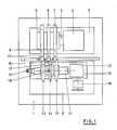
- the centerless cylindrical grinding machine which is only indicated schematically in FIG. 1, has a grinding carriage 2 on a machine bed 1, on which a grinding wheel shaft 3 with its drive device 4 is mounted.
- the grinding wheel shaft 3 carries three rigidly mounted grinding wheels 5, 6 and 7 at an axial distance from one another, which are designed on their circumference in accordance with the outer contour of the workpieces 8 to be ground.
- a regulating disc shaft 11 with the regulating disc drive 12 is mounted on a swivel support 10.
- the regulating wheel shaft 11 carries three regulating wheels 13, 14 and 15 at an axial distance from one another.
- the regulating wheels 13, 14 and 15 are frustoconical in shape and guide the workpieces 8 during the grinding process.
- the distance between each regulating wheel 13, 14 and 15 and the respectively assigned one The grinding wheel 5, 6 and 7 determines the actual size of the machined workpiece 8.
- the workpieces 8 lie on a workpiece support 16 during machining and are axially pressed against an assigned workpiece stop 17.
- the support 10 carrying the regulating disk shaft 1 can be pivoted about a pivot point 19 by means of an adjusting device 18, which is only indicated schematically in FIG. 1. This changes the relative position of the two outer regulating disks 13 and 15 to the respectively assigned outer grinding disks 5 and 7, as a result of which the actual diameter of the outer workpieces 8 also changes.
- the central regulating disk 14 is attached to a hub 20, which is supported on the spherical cage 21 by the regulating disk shaft 11 in an axially displaceable manner.
- the two outer ones Regulating disks 13 and 15 are each attached to hubs 22 and 23, which are rigidly connected to the regulating disk shaft 11 by means of clamping rings 24.
- the hub 20 of the central regulating disk 14 is connected to the regulating disk shaft 11 so that it cannot rotate, but is axially displaceable.
- a push rod 28 is axially displaceable by a small amount.
- a radially extending driver pin 29 connected to the push rod 28 protrudes on both sides through bores 30 from the regulating disk shaft 11 and is connected to the hub 20.
- a helical compression spring 31 supported at the end of the longitudinal bore 27 is supported on the push rod 28 and, together with the hub 20 connected to it, tries to push it towards the end (left in FIG. 2) of the regulating disk shaft 11 from which the push rod 28 protrudes.
- the push rod 28 is connected at its end protruding from the regulating disk shaft 11 to a micrometer screw 32, which forms an axial adjustment device for the push rod 28. If the push rod 28 is axially displaced by means of the micrometer screw 27 against the force of the spring 31, the hub 20 and the central regulating disk 14 attached to it are also axially displaced. As a result of the truncated cone shape of the regulating disk 14, its effective diameter changes, that is to say the effective distance from the assigned central one Grinding wheel 6, so that the actual diameter of the middle workpiece 8 that results during plunge grinding also changes. In this way, regardless of the changes in diameter of the two outer workpieces 8 achieved, a change in diameter of the respective middle workpiece 8 is also achieved.
- FIG. 3 is structurally essentially the same as the embodiment according to FIG. 2, so that the same reference numerals are used.
- the workpieces 8 'to be machined here do not have a spherical but a cylindrical outer contour to be machined. Therefore, both the grinding wheels 5 ', 6' and 7 'as well as the respective control wheels 13', 14 'and 15' are designed on their circumference with the same cone angle, but in the opposite direction, frustoconical.
Landscapes
- Engineering & Computer Science (AREA)
- Mechanical Engineering (AREA)
- Grinding Of Cylindrical And Plane Surfaces (AREA)
Abstract
Eine spitzenlose Rundschleifmaschine für das simultane Einstechschleifen von drei Werkstücken (8) weist auf einer angetriebenen Schleifscheibenwelle (3) drei im Abstand zueinander angeordnete Schleifscheiben (5, 6, 7) auf. Die den beiden äußeren Schleifscheiben (5, 7) zugeordneten Regelscheiben (13, 15) sind starr auf einer Regelscheibenwelle (11) aufgenommen. Die der mittleren Schleifscheibe (6) zugeordnete, am Umfang kegelstumpfförmigen mittlere Regelscheibe (14) ist an einer Nabe (20) angebracht, die undrehbar, aber mittels einer Verstelleinrichtung (32) axial verschiebbar auf der Regelscheibenwelle (11) aufgenommen ist. Die Verstellung der beiden äußeren Regelscheiben (13, 15) in Bezug auf die zugeordneten Schleifscheiben (5, 7) erfolgt durch eine Verstellung der Winkellage der Regelscheibenwelle (11). Die Verstellung der mittleren Regelscheibe (14) in Bezug auf die zugeordnete mittlere Schleifscheibe (6) erfolgt unabhängig davon durch eine axiale Verschiebung der Habe (20) mit der mittleren Regelscheibe (14). 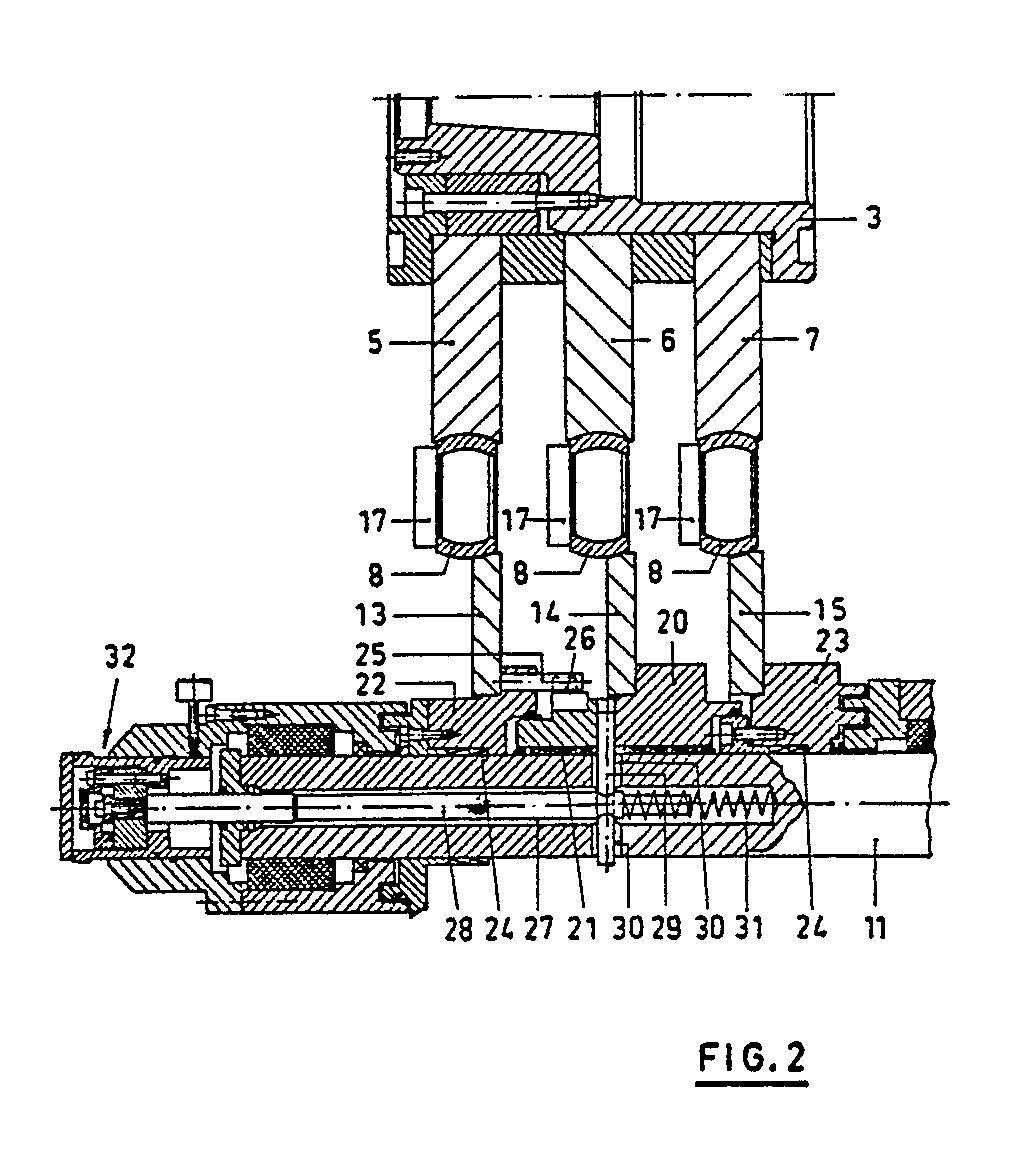
Description
Die Erfindung betrifft eine spitzenlose Rundschleifmaschine für das simultane Einstechschleifen mehrerer Werkstücke, mit zwei auf einer angetriebenen Schleifscheibenwelle in axialem Abstand zueinander starr aufgenommenen Schleifscheiben und zwei zugeordneten, am Umfang kegelstumpfförmigen Regelscheiben, die auf einer angetriebenen Regelscheibenwelle starr befestigt sind, die angenähert parallel zur Schleifscheibenwelle, jedoch in ihrer Winkelstellung relativ zu dieser verstellbar angeordnet ist.The invention relates to a centerless cylindrical grinding machine for the simultaneous plunge grinding of several workpieces, with two grinding wheels rigidly received on a driven grinding wheel shaft at an axial distance from one another and two associated regulating wheels which are frusto-conical on the circumference and which are rigidly fastened on a driven control wheel shaft, which are approximately parallel to the grinding wheel shaft, but is arranged adjustable in its angular position relative to this.
Mit diesen bekannten spitzenlosen Rundschleifmaschinen können im Einstechschleifverfahren jeweils gleichzeitig zwei Werkstücke bearbeitet werden. Da das Zustellmaß für die Regelscheiben den jeweils erzielten Werkstückdurchmesser bestimmt und vom jeweiligen Abnutzungsgrad der Schleifscheiben bzw. der Regelscheiben abhängt, ist es erforderlich, für beide Regelscheiben gesondert voneinander eine Korrektur der Zustellung vorzunehmen.With these known centerless cylindrical grinding machines, two workpieces can be machined simultaneously in the plunge-cut grinding process. Since the infeed dimension for the regulating wheels determines the workpiece diameter achieved in each case and depends on the degree of wear of the grinding wheels or the regulating wheels, it is necessary to correct the infeed separately for both regulating wheels.
Diese Korrektur erfolgt bei den bekannten spitzenlosen Rundschleifmaschinen für die Bearbeitung von zwei Werkstücken dadurch, daß die Winkelstellung der angenähert parallel zur Schleifscheibenwelle angeordneten Regelscheibenwelle verstellt wird. Üblicherweise wird die Regelscheibenwelle um einen angenähert zwischen den beiden Regelscheiben liegenden Schwenkpunkt mittels einer Verstelleinrichtung um einen geringen Winkelbetrag verstellt. Diese Verstellung erfolgt in Abhängigkeit von den an beiden Werkstücken gemessenen Durchmessern um einen solchen Winkelbetrag, daß bei der nachfolgenden Bearbeitung wieder gleiche Durchmesser der Werkstücke erzielt werden. Diese Verstellbewegung wird der quer zur Achse der Schleifscheibenwelle gerichteten Zustellbewegung der Regelscheibenwelle überlagert. Da jeweils nur zwei Werkstücke gleichzeitig bearbeitet werden können, ist die Arbeitskapazität dieser Rundschleifmaschine beschränkt.This correction is carried out in the known centerless cylindrical grinding machines for machining two workpieces in that the angular position of the regulating wheel shaft arranged approximately parallel to the grinding wheel shaft is adjusted. Usually the regulating wheel shaft is approximated by one between the two The regulating disc lying pivot point is adjusted by a small angular amount by means of an adjusting device. This adjustment takes place as a function of the diameters measured on both workpieces by such an angular amount that the same diameters of the workpieces are again achieved in the subsequent machining. This adjustment movement is superimposed on the infeed movement of the regulating wheel shaft directed transversely to the axis of the grinding wheel shaft. Since only two workpieces can be machined at a time, the working capacity of this cylindrical grinding machine is limited.
Aufgabe der Erfindung ist es daher, eine spitzenlose Rundschleifmaschine der eingangs genannten Gattung so auszubilden, daß darauf mindestens drei Werkstücke gleichzeitig im Einstechschleifverfahren bearbeitet werden können.The object of the invention is therefore to design a centerless cylindrical grinding machine of the type mentioned in the introduction in such a way that at least three workpieces can be machined on it simultaneously in the plunge-cut grinding process.
Diese Aufgabe wird erfindungsgemäß dadurch gelöst, daß zwischen den beiden Schleifscheiben mindestens eine mittlere Schleifscheibe starr auf der Schleifscheibenwelle aufgenommen ist und daß der mittleren Schleifscheibe jeweils eine zwischen den beiden starr befestigten Regelscheiben angeordnete mittlere Regelscheibe zugeordnet ist, die auf einer drehfest und axial verstellbar auf der Regelscheibenwelle aufgenommenen Nabe befestigt ist.This object is achieved in that at least one middle grinding wheel is rigidly received on the grinding wheel shaft between the two grinding wheels and that the middle grinding wheel is assigned a middle regulating wheel arranged between the two rigidly fastened regulating wheels, which is rotatably and axially adjustable on the Control wheel shaft is attached to the hub.
Die mittlere Regelscheibe kann relativ zu den beiden starr angeordneten Regelscheiben axial verstellt werden. Da sie - wie auch die anderen Regelscheiben - kegelstumpfförmig gestaltet ist, verändert sich bei ihrer axialen Verschiebung ihr wirksamer Durchmesser gegenüber dem Werkstück, das in axial festliegender Lage und daher in gleichbleibender Ausrichtung zu der zugeordneten Einstech-Schleifscheibe geführt wird. Während die Zustellkorrektur der beiden äußeren, starr auf der Regelscheibenwelle aufgenommenen Regelscheiben durch die Winkelverstellung der Regelscheibenwelle gegenüber der Schleifscheibenwelle erfolgt, geschieht die Veränderung des wirksamen Durchmessers der mittleren Regelscheibe durch deren axiale Verstellung. Beide Verstellungen erfolgen in Abhängigkeit von den bei einem simultanen Einstechschleifvorgang erzielten Istdurchmessern der Werkstücke.The middle regulating disc can be adjusted axially relative to the two rigidly arranged regulating discs. Since it - like the other regulating disks - has a frustoconical shape, its effective diameter changes with its axial displacement compared to the workpiece, which is guided in an axially fixed position and therefore in a constant orientation to the assigned plunge-cut grinding wheel. During the infeed correction of the two outer regulating discs rigidly held on the regulating disc shaft by means of the angle adjustment of the regulating wheel shaft compared to the grinding wheel shaft, the effective diameter of the middle regulating wheel is changed by its axial adjustment. Both adjustments are made depending on the actual work piece diameters achieved in a simultaneous plunge grinding process.
Gemäß einer bevorzugten Ausführung der Erfindung ist vorgesehen, daß die die mittlere Regelscheibe tragende Nabe über mindestens einen Mitnehmer mit einer in einer Längsbohrung der Regelscheibenwelle axial verschiebbaren Schubstange verbunden ist, die an einem Ende der Regelscheibenwelle mit einer Verstelleinrichtung verbunden ist. Damit wird erreicht, daß die Verstellung der mittleren Regelscheibe mittels einer am Ende der Regelscheibenwelle von außen gut zugänglichen Verstelleinrichtung vorgenommen werden kann, die beispielsweise eine Mikrometerschraube ist.According to a preferred embodiment of the invention it is provided that the hub carrying the central regulating disc is connected via at least one driver to a push rod which is axially displaceable in a longitudinal bore of the regulating disc shaft and which is connected to an adjusting device at one end of the regulating disc shaft. It is thereby achieved that the adjustment of the central regulating disk can be carried out by means of an adjustment device which is easily accessible from the outside at the end of the regulating disk shaft and which is, for example, a micrometer screw.
Weitere Ausgestaltungen des Erfindungsgedankens sind Gegenstand weiterer abhängiger Ansprüche.Further developments of the inventive concept are the subject of further dependent claims.
Nachfolgend werden Ausführungsbeispiele der Erfindung näher erläutert, die in der Zeichnung dargestellt sind. Es zeigt:
- Fig. 1 eine stark vereinfachte Draufsicht auf eine spitzenlose Rundschleifmaschine für das simultane Einstechschleifen von drei Werkstücken mit balliger Außenkontur,
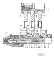
- Fig. 2 einen vergrößerten Teil-Horizontalschnitt durch die Schleifscheibenwelle und die Regelscheibenwelle der Rundschleifmaschine nach Fig. 1 und
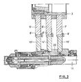
- Fig. 3 einen Schnitt entsprechend der Fig. 2 bei einer spitzenlosen Rundschleifmaschine für das simultane Einstechschleifen von drei zylindrischen Werkstücken.
- 1 is a greatly simplified top view of a centerless cylindrical grinding machine for the simultaneous plunge grinding of three workpieces with a spherical outer contour,
- Fig. 2 is an enlarged partial horizontal section through the grinding wheel shaft and the control wheel shaft of the cylindrical grinding machine according to Fig. 1 and
- Fig. 3 shows a section corresponding to FIG. 2 in a centerless cylindrical grinding machine for the simultaneous plunge grinding of three cylindrical workpieces.
Die in Fig. 1 nur schematisch angedeutete spitzenlose Rundschleifmaschine weist auf einem Maschinenbett 1 einen Schleifschlitten 2 auf, auf dem eine Schleifscheibenwelle 3 mit ihrer Antriebseinrichtung 4 gelagert ist. Die Schleifscheibenwelle 3 trägt in axialem Abstand zueinander drei starr aufgenommene Schleifscheiben 5, 6 und 7, die an ihrem Umfang entsprechend der zu schleifenden Außenkontur der Werkstücke 8 gestaltet sind.The centerless cylindrical grinding machine, which is only indicated schematically in FIG. 1, has a
In einem gegenüberliegenden Regelscheibenschlitten 9 ist auf einem Schwenksupport 10 eine Regelscheibenwelle 11 mit dem Regelscheibenantrieb 12 gelagert. Die Regelscheibenwelle 11 trägt in axialem Abstand zueiander drei Regelscheiben 13, 14 und 15. Die Regelscheiben 13, 14 und 15 sind an ihrem Umfang kegelstumpfförmig und führen beim Schleifvorgang die Werkstücke 8. Der Abstand zwischen jeder Regelscheibe 13, 14 und 15 und der jeweils zugeordneten Schleifscheibe 5, 6 bzw. 7 bestimmt das jeweils erzielte Istmaß des bearbeiteten Werkstücks 8. Die Werkstücke 8 liegen bei der Bearbeitung auf einer Werkstückauflage 16 und werden axial jeweils gegen einen zugeordneten Werkstückanschlag 17 gedrückt.In an opposing regulating
Mittels einer in Fig. 1 nur schematisch angedeuteten Verstelleinrichtung 18 kann der die Regelscheibenwelle 1 tragende Support 10 um einen Schwenkpunkt 19 geschwenkt werden. Dadurch verändert sich die Relativlage der beiden äußeren Regelscheiben 13 und 15 zu den jeweils zugeordneten äußeren Schleifscheiben 5 und 7, wodurch sich auch der erzielte Istdurchmesser der äußeren Werkstücke 8 ändert.The
Wie in Fig. 2 deutlicher dargestellt, ist die mittlere Regelscheibe 14 auf einer Nabe 20 angebracht, die auf einem Kugelkäfig 21 axial verschiebbar von der Regelscheibenwelle 11 getragen wird. Die beiden äußeren Regelscheiben 13 und 15 sind jeweils an Naben 22 und 23 befestigt, die mittels Klemmringen 24 starr mit der Regelscheibenwelle 11 verbunden sind.As shown more clearly in FIG. 2, the central regulating
Ein mit der Nabe 22 und somit starr mit der Regelscheibenwelle 11 verbundener, achsparalleler Mitnehmer 25 greift in eine Mitnahmeaussparung 26 am Umfang der die mittlere Regelscheibe 14 tragenden Nabe 20 und ist dort axial beweglich geführt. Auf diese Weise ist die Nabe 20 der mittleren Regelscheibe 14 undrehbar, jedoch axial verschiebbar mit der Regelscheibenwelle 11 verbunden.An axially
In einer Längsbohrung 27 der Regelscheibenwelle 11 ist eine Schubstange 28 axial um einen geringen Betrag verschiebbar aufgenommen. Ein mit der Schubstange 28 verbundener, sich radial erstreckender Mitnehmerstift 29 ragt nach beiden Seiten durch Bohrungen 30 aus der Regelscheibenwelle 11 heraus und ist mit der Nabe 20 verbunden.In a
Eine am Ende der Längsbohrung 27 abgestütze Schraubendruckfeder 31 stützt sich an der Schubstange 28 ab und sucht diese zusammen mit der damit verbundenen Nabe 20 zu dem Ende (links in Fig. 2) der Regelscheibenwelle 11 zu drücken, aus dem die Schubstange 28 herausragt.A
Die Schubstange 28 ist an ihrem aus der Regelscheibenwelle 11 herausragenden Ende mit einer Mikrometerschraube 32 verbunden, die eine axiale Verstelleinrichtung für die Schubstange 28 bildet. Wenn die Schubstange 28 mittels der Mikrometerschraube 27 gegen die Kraft der Feder 31 axial verschoben wird, werden damit auch die Nabe 20 und die daran angebrachte mittlere Regelscheibe 14 axial verschoben. Infolge der Kegelstumpfform der Regelscheibe 14 verändert sich dadurch ihr wirksamer Durchmesser, d. h. der wirksame Abstand zu der zugeordneten mittleren Schleifscheibe 6, so daß sich auch der beim Einstechschleifen ergebende Istdurchmesser des jeweils mittleren Werkstücks 8 ändert. Auf diese Weise wird unabhängig von den erzielten Durchmesseränderungen der beiden äußeren Werkstücke 8 auch eine Durchmesseränderung des jeweils mittleren Werkstücks 8 erzielt.The
Die in Fig. 3 gezeigte Ausführungsform gleicht in konstruktiver Hinsicht im wesentlichen der Ausführung nach Fig. 2, so daß gleiche Bezugszeichen verwendet werden. Die hierbei zu bearbeitenden Werkstücke 8′ weisen jedoch keine ballige, sondern eine zylindrische zu berbeitende Außenkontur auf. Deshalb sind sowohl die Schleifscheiben 5′, 6′ und 7′ als auch die ihnen jeweils zugeordneten Regelscheiben 13′, 14′ und 15′ an ihrem Umfang mit einem gleichen kegelwinkel, jedoch in entgegengesetzter Richtung, kegelstumpfförmig gestaltet. Auch hierbei erfolgt die Veränderung des Istdurchmessers der beiden äußeren Werkstücke 8′ durch eine Verschwenkung der Regelscheibenwelle in der Weise, wie es anhand von Fig. 1 erläutert wurde. Die Veränderung des wirksamen Abstandes zwischen der mittleren Schleifscheibe 6′ und der zugeordneten mittleren Regelscheibe 14′ erfolgt in der bei Fig. 2 beschriebenen Weise durch eine axiale Verstellung der Nabe 20, die die mittlere Regelscheibe 14′ trägt. Dadurch läßt sich auch der erzielte Istdurchmesser des mittleren Werkstücks 8′ verändern.The embodiment shown in FIG. 3 is structurally essentially the same as the embodiment according to FIG. 2, so that the same reference numerals are used. The
Anstelle nur einer einzigen mittleren Schleifscheibe 6 bzw. 6′ mit einer zugeordneten mittleren Regelscheibe 14 bzw. 14′ können auch zwei oder mehr mittlere Schleifscheiben und mittlere Regelscheiben zwischen den jeweils äußeren Schleifscheiben 5 und 7 bzw. 5′ und 7′ angeordnet werden, wobei die Verstellung aller mittleren Regelscheiben in der beschriebenen Weise erfolgt, nämlich durch gesonderte axiale Verschiebung einer die Regelscheibe tragenden Nabe auf der Regelscheibenwelle 11.Instead of only a single
Claims (6)
dadurch gekennzeichnet,
daß zwischen den beiden äußeren Schleifscheiben (5, 7 bzw. 5′, 7′) mindestens eine mittlere Schleifscheibe (6 bzw. 6′) starr auf der Schleifscheibenwelle (3) aufgenommen ist und daß der mittleren Schleifscheibe (6 bzw. 6′) jeweils eine zwischen den beiden starr befestigten Regelscheiben (13, 15 bzw. 13′, 15′) angeordnete mittlere Regelscheibe (14 bzw. 14′) zugeordnet ist, die auf einer drehfest und axial verstellbar auf der Regelscheibenwelle (11) aufgenommenen Nabe (20) befestigt ist.1. Centerless cylindrical grinding machine for simultaneous plunge grinding of several workpieces (8, 8 '), with two on a driven grinding wheel shaft (3) axially spaced grinding wheels (5, 7 or 5', 7 ') and two assigned, on Circumferential frustoconical regulating discs (13, 15 or 13 ', 15') which are rigidly attached to a driven regulating disc shaft (11) which is arranged approximately parallel to the grinding wheel shaft (3), but is adjustable in its angular position relative to the latter,
characterized,
that between the two outer grinding wheels (5, 7 or 5 ', 7') at least one middle grinding wheel (6 or 6 ') is rigidly received on the grinding wheel shaft (3) and that the middle grinding wheel (6 or 6') In each case one between the two rigidly fixed regulating discs (13, 15 or 13 ', 15') is arranged, which is arranged on a regulating disc (14. 14 ') which is arranged on a rotatably and axially adjustable on the regulating disc shaft (11) ) is attached.
dadurch gekennzeichnet, daß die die mittlere Regelscheibe (14 bzw. 14′) tragende Nabe (20) über mindestens einen Mitnehmer (29) mit einer in einer Längsbohrung (27) der Regelscheibenwelle (11) axial verschiebbaren Schubstange (28) verbunden ist, die an einem Ende der Regelscheibenwelle (11) mit einer Verstelleinrichtung (32) verbunden ist.2. Centerless cylindrical grinding machine according to claim 1,
characterized in that the hub (20) carrying the central regulating disk (14 or 14 ′) is connected via at least one driver (29) to a push rod (28) which is axially displaceable in a longitudinal bore (27) of the regulating disk shaft (11) and which at one end of the regulating wheel shaft (11) is connected to an adjusting device (32).
dadurch gekennzeichnet, daß die Verstelleinrichtung (32) eine Mikrometerschraube ist.3. Centerless cylindrical grinding machine according to claim 2,
characterized in that the adjusting device (32) is a micrometer screw.
dadurch gekennzeichnet, daß ein sich im wesentlichen achsparallel erstreckender, mit der Regelscheibenwelle (11) starr verbundener Mitnehmer (25) in eine Mitnahmeaussparung (26) der Nabe (20) der mittleren Regelscheibe (14 bzw. 14′) greift.5. Centerless cylindrical grinding machine according to claim 1,
characterized in that an essentially axially parallel driver (25) rigidly connected to the regulating disk shaft (11) engages in a driving recess (26) in the hub (20) of the central regulating disk (14 or 14 ').
dadurch gekennzeichnet, daß zwischen den beiden äußeren Schleifscheiben (5, 7 bzw. 5′, 7′) mehrere mittlere Schleifscheiben starr auf der Schleifscheibenwelle (3) aufgenommen sind, denen jeweils eine gesonderte, auf der Regelscheibenwelle (11) unabhängig voneinander axial verschiebbare Regelscheibe zugeordnet ist.6. Centerless cylindrical grinding machine according to claim 1,
characterized in that between the two outer grinding wheels (5, 7 and 5 ', 7') several middle grinding wheels are rigidly received on the grinding wheel shaft (3), each of which has a separate control wheel which is axially displaceable independently of one another on the control wheel shaft (11) assigned.
Applications Claiming Priority (2)
| Application Number | Priority Date | Filing Date | Title |
|---|---|---|---|
| DE3820041 | 1988-06-13 | ||
| DE19883820041 DE3820041A1 (en) | 1988-06-13 | 1988-06-13 | CENTERLESS ROUND GRINDING MACHINE |
Publications (2)
| Publication Number | Publication Date |
|---|---|
| EP0346584A2 true EP0346584A2 (en) | 1989-12-20 |
| EP0346584A3 EP0346584A3 (en) | 1990-07-11 |
Family
ID=6356422
Family Applications (1)
| Application Number | Title | Priority Date | Filing Date |
|---|---|---|---|
| EP89106553A Withdrawn EP0346584A3 (en) | 1988-06-13 | 1989-04-13 | Cylindrical centreless guiding machine |
Country Status (2)
| Country | Link |
|---|---|
| EP (1) | EP0346584A3 (en) |
| DE (1) | DE3820041A1 (en) |
Family Cites Families (2)
| Publication number | Priority date | Publication date | Assignee | Title |
|---|---|---|---|---|
| US2017875A (en) * | 1932-12-05 | 1935-10-22 | Frederick J Theler | Lapping machine |
| DE801500C (en) * | 1949-01-30 | 1951-01-08 | Herminghausen Werke G M B H | Device for the simultaneous processing of two lateral grinding points on workpieces to be ground on centerless cylindrical grinding machines using two grinding wheels |
-
1988
- 1988-06-13 DE DE19883820041 patent/DE3820041A1/en not_active Withdrawn
-
1989
- 1989-04-13 EP EP89106553A patent/EP0346584A3/en not_active Withdrawn
Also Published As
| Publication number | Publication date |
|---|---|
| EP0346584A3 (en) | 1990-07-11 |
| DE3820041A1 (en) | 1989-12-21 |
Similar Documents
| Publication | Publication Date | Title |
|---|---|---|
| DE3435313C2 (en) | Device for external cylindrical grinding | |
| DE10234707A1 (en) | Method and device for grinding a rotationally symmetrical machine component | |
| DE102010010758A1 (en) | Centerless cylindrical grinding machine for grinding bar-shaped workpieces and method for centerless cylindrical grinding of bar-shaped workpieces | |
| DE2824073C2 (en) | Centerless grinding machine | |
| DE6902724U (en) | GRINDING MACHINE FOR PRECISION GRINDING OF A TOOL. | |
| DE1933575B2 (en) | Device for grinding outer or inner surfaces of workpieces | |
| CH663923A5 (en) | DRESSING DEVICE FOR TRAIN-CONTROLLED DRESSING OF GRINDING DISC PROFILES. | |
| DE1300834B (en) | Device for honing cylindrical workpieces | |
| DE2718731C2 (en) | External cylindrical grinding machine | |
| DE2712029C3 (en) | Cam grinding machine | |
| DE2243884A1 (en) | DEVICE FOR DRESSING GRINDING WHEELS | |
| EP0346584A2 (en) | Cylindrical centreless guiding machine | |
| DE2335575B2 (en) | ||
| DE4012658C2 (en) | Spectacle lens edge grinding machine | |
| DE69706974T3 (en) | grinding machine | |
| DE4025745C2 (en) | ||
| EP0425924A1 (en) | Profile rolling machine for the production of circumferentially profiled, hollow cylindrical or cup-shaped platework-pieces | |
| DE4011715C1 (en) | ||
| EP0176654B1 (en) | Method and device for high-speed profile grinding of dynamically balanced workpieces | |
| DE1502492B1 (en) | Copy grinder | |
| EP0045433A1 (en) | Polishing or grinding machine having an axially reciprocating and rotatable tool spindle | |
| DE2453885A1 (en) | METHOD AND DEVICE FOR MANUFACTURING CURVED DISCS | |
| DE1234574B (en) | Grinding machine for grinding parallel slot surfaces | |
| DE3517802A1 (en) | Headstock for a grinding machine | |
| DE4316765A1 (en) | Apparatus for producing or machining gears |
Legal Events
| Date | Code | Title | Description |
|---|---|---|---|
| PUAI | Public reference made under article 153(3) epc to a published international application that has entered the european phase |
Free format text: ORIGINAL CODE: 0009012 |
|
| AK | Designated contracting states |
Kind code of ref document: A2 Designated state(s): DE ES FR GB IT NL SE |
|
| PUAL | Search report despatched |
Free format text: ORIGINAL CODE: 0009013 |
|
| AK | Designated contracting states |
Kind code of ref document: A3 Designated state(s): DE ES FR GB IT NL SE |
|
| 17P | Request for examination filed |
Effective date: 19901130 |
|
| 17Q | First examination report despatched |
Effective date: 19920730 |
|
| STAA | Information on the status of an ep patent application or granted ep patent |
Free format text: STATUS: THE APPLICATION IS DEEMED TO BE WITHDRAWN |
|
| 18D | Application deemed to be withdrawn |
Effective date: 19930525 |