EP0346516A1 - Regal mit Seitenwänden aus mehrlagigem Faltmaterial - Google Patents
Regal mit Seitenwänden aus mehrlagigem Faltmaterial Download PDFInfo
- Publication number
- EP0346516A1 EP0346516A1 EP88109612A EP88109612A EP0346516A1 EP 0346516 A1 EP0346516 A1 EP 0346516A1 EP 88109612 A EP88109612 A EP 88109612A EP 88109612 A EP88109612 A EP 88109612A EP 0346516 A1 EP0346516 A1 EP 0346516A1
- Authority
- EP
- European Patent Office
- Prior art keywords
- support rods
- side walls
- sleeve
- shelf
- walls made
- Prior art date
- Legal status (The legal status is an assumption and is not a legal conclusion. Google has not performed a legal analysis and makes no representation as to the accuracy of the status listed.)
- Granted
Links
- 239000000463 material Substances 0.000 title claims abstract description 12
- 238000003780 insertion Methods 0.000 claims abstract description 3
- 230000037431 insertion Effects 0.000 claims abstract description 3
- 238000013459 approach Methods 0.000 description 6
- 239000002023 wood Substances 0.000 description 2
- 241000209035 Ilex Species 0.000 description 1
- 230000015572 biosynthetic process Effects 0.000 description 1
- 238000010276 construction Methods 0.000 description 1
- 238000004519 manufacturing process Methods 0.000 description 1
Images
Classifications
-
- F—MECHANICAL ENGINEERING; LIGHTING; HEATING; WEAPONS; BLASTING
- F16—ENGINEERING ELEMENTS AND UNITS; GENERAL MEASURES FOR PRODUCING AND MAINTAINING EFFECTIVE FUNCTIONING OF MACHINES OR INSTALLATIONS; THERMAL INSULATION IN GENERAL
- F16B—DEVICES FOR FASTENING OR SECURING CONSTRUCTIONAL ELEMENTS OR MACHINE PARTS TOGETHER, e.g. NAILS, BOLTS, CIRCLIPS, CLAMPS, CLIPS OR WEDGES; JOINTS OR JOINTING
- F16B12/00—Jointing of furniture or the like, e.g. hidden from exterior
- F16B12/10—Jointing of furniture or the like, e.g. hidden from exterior using pegs, bolts, tenons, clamps, clips, or the like
- F16B12/12—Jointing of furniture or the like, e.g. hidden from exterior using pegs, bolts, tenons, clamps, clips, or the like for non-metal furniture parts, e.g. made of wood, of plastics
- F16B12/22—Jointing of furniture or the like, e.g. hidden from exterior using pegs, bolts, tenons, clamps, clips, or the like for non-metal furniture parts, e.g. made of wood, of plastics using keyhole-shaped slots and pins
-
- A—HUMAN NECESSITIES
- A47—FURNITURE; DOMESTIC ARTICLES OR APPLIANCES; COFFEE MILLS; SPICE MILLS; SUCTION CLEANERS IN GENERAL
- A47B—TABLES; DESKS; OFFICE FURNITURE; CABINETS; DRAWERS; GENERAL DETAILS OF FURNITURE
- A47B47/00—Cabinets, racks or shelf units, characterised by features related to dismountability or building-up from elements
- A47B47/06—Cabinets, racks or shelf units, characterised by features related to dismountability or building-up from elements made mainly of cardboard, textile, paper, or the like, e.g. with separate frame of other materials
-
- A—HUMAN NECESSITIES
- A47—FURNITURE; DOMESTIC ARTICLES OR APPLIANCES; COFFEE MILLS; SPICE MILLS; SUCTION CLEANERS IN GENERAL
- A47F—SPECIAL FURNITURE, FITTINGS, OR ACCESSORIES FOR SHOPS, STOREHOUSES, BARS, RESTAURANTS OR THE LIKE; PAYING COUNTERS
- A47F5/00—Show stands, hangers, or shelves characterised by their constructional features
- A47F5/10—Adjustable or foldable or dismountable display stands
- A47F5/11—Adjustable or foldable or dismountable display stands made of cardboard, paper or the like
- A47F5/118—Combinations of cardboard and other materials, e.g. wood
Definitions
- the invention relates to a shelf with side walls made of multilayered folding material, with which support rods are releasably connected, onto which trays for receiving and presenting goods are placed.
- Such shelves are known.
- through holes are made in the side walls, into which the support rods are inserted with their ends.
- this has the disadvantage that the outer sides of the side walls are optically interrupted and disturbed by the ends of the support rods inserted there, so that, for example, no continuous advertising labels can be attached there.
- the invention avoids these disadvantages. It is based on the task of proposing a shelf with the features mentioned at the beginning, in which the outer sides of the side walls are undisturbed and not interrupted.
- the invention is characterized in that the respective outer layers of the multilayer side walls are smooth and not interrupted, that at least their innermost layer has through holes for receiving the ends of the support rods and that an insertion space for downward-facing approaches between the layers are formed at the ends of the support rods.
- the support rods are thus only on the correspondingly profiled through holes of the inner layers of the Side walls held, the downward-facing approaches at the ends of the support rods, which engage in corresponding spaces between the multilayer side walls, ensure that the support rods do not slip out of the through holes and thus remain correctly positioned.
- the approaches at the ends of the support rods There are several options for the formation of the approaches at the ends of the support rods. So you can form the support rods with their approaches in one piece from plastic material. In a preferred embodiment, however, the actual support rods are made of wood-based material, because this is cheaper. In this embodiment, the approaches are then molded onto sleeves made of plastic material, which are pushed onto the support rods.
- At least one inwardly facing, rib-shaped elevation with a leading edge is formed on at least one inner surface of the sleeve.
- the survey takes up dimensional tolerances between the inside diameter of the sleeve and the profile of the support rod.
- a through hole can also be provided in the sleeve for the same purpose, so that the sleeve is then correctly positioned there by means of a screw screwed through the hole into the material of the support rod.
- the basic structure of the shelf is of conventional construction.
- it consists of a foot, a rear wall and two side walls, which parts are preferably made of folded material.
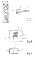
- Fig. 1 shows one of the side walls according to the invention, which has three layers in this example. It consists of a smooth, continuous outer layer 1, an inner layer 3 and an intermediate layer 2.
- holes 4 are provided at predetermined locations, namely where support rods are to be held, for receiving the ends of the support rods 5.
- the intermediate layer 2 also has a hole 6a, which is guided somewhat lower down than that hole 4 in front of it. See also FIG. 2.
- a sleeve 6 is pushed, at the outer end of which a downwardly facing projection 7 is formed.
- the dimensions are such that the relevant end of the support rod together with the sleeve and the neck can be inserted through the hole 4 into the receptacle 6a and then lowered so that the sleeve or the end of the support rod on the lower edge of the hole 4th rests and the approach 7 is in the lower part of the receptacle 6, whereby the end of the support rod is anchored there.
- Fig. 3 also shows that the sleeve can have rib-shaped run-up edges 8, whereby the sleeve can be pushed onto the support bar firmly and in a snug fit despite manufacturing tolerances and / or a shrinkage of the support bar made of wood-based material.
- the sleeve can also have a hole 9 through which the sleeve can be attached to the support rod.
- a front and a rear support rod are provided on the shelf at the same level, on which a tray or the like can then be placed.
- a tray or the like can then be placed.
- many of these pairs of support rods are then arranged one above the other at different levels to accommodate a corresponding number of trays, which are also preferably made of folded material.
Landscapes
- Engineering & Computer Science (AREA)
- General Engineering & Computer Science (AREA)
- Mechanical Engineering (AREA)
- Life Sciences & Earth Sciences (AREA)
- Wood Science & Technology (AREA)
- Assembled Shelves (AREA)
- Rigid Containers With Two Or More Constituent Elements (AREA)
- Packaging Of Annular Or Rod-Shaped Articles, Wearing Apparel, Cassettes, Or The Like (AREA)
- Pallets (AREA)
- Absorbent Articles And Supports Therefor (AREA)
Abstract
Description
- Die Erfindung betrifft ein Regal mit Seitenwänden aus mehrlagigem Faltmaterial, mit denen Tragstangen lösbar verbunden sind, auf die Trays für die Aufnahme und Darbietung von Waren aufgesetzt sind.
- Derartige Regale sind bekannt. Bei einer Ausführungsform sind in den Seitenwänden Durchgangslöcher angebracht, in die die Tragstangen mit ihren Enden eingesteckt sind. Damit ist aber der Nachteil verbunden, daß die Außenseiten der Seitenwände durch die dort hindurchgesteckten Enden der Tragstangen optisch unterbrochen und gestört sind, so daß beispielsweise keine durchgehenden Werbeaufschriften dort angebracht werden können.
- Die Erfindung vermeidet diese Nachteile. Ihr liegt die Aufgabe zugrunde, ein Regal mit den eingangs genannten Merkmalen vorzuschlagen, bei dem die Außenseiten der Seitenwände ungestört und nicht unterbrochen sind.
- Zur Lösung dieser Aufgabe ist die Erfindung dadurch gekennzeichnet, daß die jeweils äußeren Lagen der mehrlagigen Seitenwände glatt durchgehend und nicht unterbrochen sind, daß zumindest deren innerste Lage Durchgangslöcher zur Aufnahme der Enden der Tragstangen hat und daß zwischen den Lagen ein Einsteckraum für nach unten weisende Ansätze an den Enden der Tragstangen ausgebildet sind.
- Die Tragstangen werden somit lediglich an den entsprechend profilierten Durchgangslöchern der inneren Lagen der Seitenwände gehalten, wobei die nach unten weisenden Ansätze an den Enden der Tragstangen, die in entsprechende Zwischenräume der mehrlagigen Seitenwände eingreifen, dafür sorgen, daß die Tragstangen aus den Durchgangslöchern nicht herausrutschen und somit richtig positioniert bleiben.
- Für die Ausbildung der Ansätze an den Enden der Tragstangen gibt es mehrere Möglichkeiten. So kann man die Tragstangen mit ihren Ansätzen einstückig aus Kunststoffmaterial formen. Bei einer bevorzugten Ausführungsform bestehen die eigentlichen Tragstangen allerdings aus Holzwerkstoff, weil dies billiger ist. Bei dieser Ausführungsform sind dann die Ansätze an Hülsen aus Kunststoffmaterial angeformt, die auf die Tragstangen aufgeschoben sind.
- Um die Hülsen an den eigentlichen Tragstangen unverlierbar zu befestigen, wird es bevorzugt, wenn an wenigstens einer Innenfläche der Hülse wenigstens eine nach innen weisende, rippenförmige Erhebung mit einer Auflaufkante ausgebildet ist. Die Erhebung nimmt Maßtoleranzen zwischen dem lichten Durchmesser der Hülse und dem Profil der Tragstange auf.
- Alternativ oder zusätzlich kann in der Hülse zu demselben Zweck auch ein Durchgangsloch vorgesehen sein, so daß dann die Hülse über ein durch das Loch in das Material der Tragstange eingeschraubte Schraube dort richtig positioniert wird.
- Die Erfindung wird im folgenden anhand eines Ausführungs beispieles näher erläutert, aus dem sich weitere wichtige Merkmale ergeben. Es zeigt:
- Fig. 1 - in auseinandergezogener Darstellung einen Schnitt durch die linke Seitenwand eines erfindungsgemäßen Regals in einem Ausschnitt mit davor befindlichem Ende einer der Tragstangen;
- Fig. 2 - eine Ansicht in Richtung des Pfeiles A von Fig. 1, wobei zusätzlich das betreffende Ende der Tragstange angedeutet ist;
- Fig. 3 - in demgegenüber vergrößertem Maßstab eine Draufsicht auf die Hülse.
- Es sei erwähnt, daß das Regal in seinem Grundaufbau herkömmlich konstruiert ist. Beispielsweise besteht es aus einem Fuß, einer Rückwand und zwei Seitenwänden, welche Teile bevorzugt aus Faltmaterial hergestellt sind.
- Fig. 1 zeigt eine der erfindungsgemäßen Seitenwände, die bei diesem Beispiel dreilagig ist. Sie besteht aus einer glatt durchgehenden Außenlage 1, einer Innenlage 3 und einer Zwischenlage 2.
- In der Innenlage sind an vorbestimmten Stellen, nämlich dort, wo Tragstangen gehalten werden sollen, Löcher 4 angebracht zur Aufnahme der Enden der Tragstangen 5. An dieser Stelle weist auch die Zwischenlage 2 ein Loch 6a auf, welches etwas tiefer nach unten geführt ist als das davor befindliche Loch 4. Siehe auch Fig. 2.
- Auf das betreffende Ende der Tragstange 5 ist eine Hülse 6 aufgeschoben, an deren äußeres Ende ein nach unten weisender Ansatz 7 angeformt ist. Die Abmessungen sind so getroffen, daß das betreffende Ende der Tragstange mitsamt der Hülse und dem Ansatz durch das Loch 4 in die Aufnahme 6a eingeschoben und dann abgesenkt werden kann, so daß die Hülse bzw. das Ende der Tragstange auf dem unteren Rand des Loches 4 aufruht und der Ansatz 7 sich im unteren Teil der Aufnahme 6 befindet, wodurch die Tragstange mit ihrem Ende dort verankert wird.
- Fig. 3 läßt noch erkennen, daß die Hülse rippenförmige Auflaufkanten 8 haben kann, wodurch die Hülse trotz Fertigungstoleranzen und/oder eines Schwundes der aus Holzwerkstoff bestehenden Tragstange fest und in einem Paßsitz auf die Tragstange aufgeschoben werden kann. Zu diesem Zweck kann die Hülse auch ein Loch 9 haben, über die die Hülse an der Tragstange befestigt werden kann.
- Üblicherweise sind im Regal jeweils eine vordere und eine hintere Tragstange, wie vorstehend beschrieben, auf demselbe Niveau vorgesehen, auf die dann ein Tray oder dergleichen aufgesetzt werden kann. Entsprechend viele dieser Tragstangenpaare sind auf unterschiedlichen Niveaus dann übereinander angeordnet zur Aufnahme einer entsprechenden Anzahl von Trays, die ebenfalls vorzugsweise aus Faltmaterial bestehen.
Claims (4)
dadurch gekennzeichnet,
daß die jeweils äußeren Lagen (1) der mehrlagigen Seitenwände glatt durchgehend und nicht unterbrochen sind, daß zumindest deren innerste Lage (3) Durchgangslöcher (4) zur Aufnahme der Enden (6) der Tragstangen (5) hat und daß zwischen den Lagen (1,3) ein Einsteckraum (6a) für nach unten weisende Ansätze (7) an den Enden der Tragstangen (5) ausgebildet sind.
dadurch gekennzeichnet,
daß die Ansätze (7) an Hülsen (6) aus Kunststoffmaterial angeformt sind, die auf die Tragstangen (5) aufgeschoben sind.
dadurch gekennzeichnet,
daß an wenigstens einer Innenfläche der Hülse (6) wenigstens eine nach innen weisende, rippenförmige Erhebung (8) mit einer Auflaufkante ausgebildet ist.
dadurch gekennzeichnet,
daß in der Hülse ein Durchgangsloch (9) vorgesehen ist.
Priority Applications (5)
| Application Number | Priority Date | Filing Date | Title |
|---|---|---|---|
| AT88109612T ATE60495T1 (de) | 1988-06-16 | 1988-06-16 | Regal mit seitenwaenden aus mehrlagigem faltmaterial. |
| DE8816592U DE8816592U1 (de) | 1988-06-16 | 1988-06-16 | Regal mit Seitenwänden aus mehrlagigem Faltmaterial |
| DE8888109612T DE3861724D1 (de) | 1988-06-16 | 1988-06-16 | Regal mit seitenwaenden aus mehrlagigem faltmaterial. |
| EP88109612A EP0346516B1 (de) | 1988-06-16 | 1988-06-16 | Regal mit Seitenwänden aus mehrlagigem Faltmaterial |
| DE8900997U DE8900997U1 (de) | 1988-06-16 | 1989-01-30 | Regal mit Seitenwänden aus mehrlagigem Faltmaterial |
Applications Claiming Priority (1)
| Application Number | Priority Date | Filing Date | Title |
|---|---|---|---|
| EP88109612A EP0346516B1 (de) | 1988-06-16 | 1988-06-16 | Regal mit Seitenwänden aus mehrlagigem Faltmaterial |
Publications (2)
| Publication Number | Publication Date |
|---|---|
| EP0346516A1 true EP0346516A1 (de) | 1989-12-20 |
| EP0346516B1 EP0346516B1 (de) | 1991-01-30 |
Family
ID=8199063
Family Applications (1)
| Application Number | Title | Priority Date | Filing Date |
|---|---|---|---|
| EP88109612A Expired - Lifetime EP0346516B1 (de) | 1988-06-16 | 1988-06-16 | Regal mit Seitenwänden aus mehrlagigem Faltmaterial |
Country Status (3)
| Country | Link |
|---|---|
| EP (1) | EP0346516B1 (de) |
| AT (1) | ATE60495T1 (de) |
| DE (3) | DE3861724D1 (de) |
Cited By (7)
| Publication number | Priority date | Publication date | Assignee | Title |
|---|---|---|---|---|
| EP0484639A1 (de) * | 1990-11-07 | 1992-05-13 | Gustav Stabernack GmbH | Regal |
| EP0533963A1 (de) * | 1991-08-29 | 1993-03-31 | Gustav Stabernack GmbH | Zur Mono-Entsorgung geeignetes Regal |
| FR2702938A1 (fr) * | 1993-03-26 | 1994-09-30 | Socar Plv | Présentoir en un matériau semi-rigide, comportant des étagères pour l'exposition en vente d'articles divers. |
| DE9117109U1 (de) * | 1990-11-07 | 1995-11-09 | Gustav Stabernack GmbH, 36341 Lauterbach | Regalstange |
| WO2001065972A3 (es) * | 2000-03-07 | 2002-04-25 | Romero Jose Pleguezuelos | Sistema modular para la construccion de muebles especialmente en bricolaje |
| ES2172382A1 (es) * | 2000-03-07 | 2002-09-16 | Romero Jose Pleguezuelos | Sistema modular para la construccion de muebles, especialmente en bricolage. |
| NL1017957C2 (nl) * | 2001-04-27 | 2002-10-29 | Pozo Negro Beheer B V | Ligger en samenstel van ten minste één ligger en een opbouw. |
Families Citing this family (1)
| Publication number | Priority date | Publication date | Assignee | Title |
|---|---|---|---|---|
| DE202011003175U1 (de) | 2011-02-24 | 2011-06-01 | Gissler & Pass GmbH, 31552 | Regal |
Citations (4)
| Publication number | Priority date | Publication date | Assignee | Title |
|---|---|---|---|---|
| DE869263C (de) * | 1944-02-08 | 1953-03-02 | Karl Hassdenteufel | Loesbare oder nicht loesbare Verbindung von Teilen vornehmlich aus Holz oder aehnlichen Werkstoffen und Werkzeug zu ihrer Herstellung |
| FR2109202A5 (de) * | 1970-10-07 | 1972-05-26 | Gacon Freres | |
| DE8712389U1 (de) * | 1987-09-12 | 1988-01-21 | Schröter + Bake GmbH + Co KG Werke für moderne Verpackung, 8402 Neutraubling | Display-Regal |
| DE8713942U1 (de) * | 1987-10-15 | 1988-02-25 | Stange, Hans-Peter, 1000 Berlin | Möbel aus Wellpappe oder ähnlichem faltbaren Material |
-
1988
- 1988-06-16 DE DE8888109612T patent/DE3861724D1/de not_active Expired - Fee Related
- 1988-06-16 AT AT88109612T patent/ATE60495T1/de not_active IP Right Cessation
- 1988-06-16 DE DE8816592U patent/DE8816592U1/de not_active Expired - Lifetime
- 1988-06-16 EP EP88109612A patent/EP0346516B1/de not_active Expired - Lifetime
-
1989
- 1989-01-30 DE DE8900997U patent/DE8900997U1/de not_active Expired
Patent Citations (4)
| Publication number | Priority date | Publication date | Assignee | Title |
|---|---|---|---|---|
| DE869263C (de) * | 1944-02-08 | 1953-03-02 | Karl Hassdenteufel | Loesbare oder nicht loesbare Verbindung von Teilen vornehmlich aus Holz oder aehnlichen Werkstoffen und Werkzeug zu ihrer Herstellung |
| FR2109202A5 (de) * | 1970-10-07 | 1972-05-26 | Gacon Freres | |
| DE8712389U1 (de) * | 1987-09-12 | 1988-01-21 | Schröter + Bake GmbH + Co KG Werke für moderne Verpackung, 8402 Neutraubling | Display-Regal |
| DE8713942U1 (de) * | 1987-10-15 | 1988-02-25 | Stange, Hans-Peter, 1000 Berlin | Möbel aus Wellpappe oder ähnlichem faltbaren Material |
Cited By (8)
| Publication number | Priority date | Publication date | Assignee | Title |
|---|---|---|---|---|
| EP0484639A1 (de) * | 1990-11-07 | 1992-05-13 | Gustav Stabernack GmbH | Regal |
| EP0484986A1 (de) * | 1990-11-07 | 1992-05-13 | Gustav Stabernack GmbH | Regal |
| DE9117109U1 (de) * | 1990-11-07 | 1995-11-09 | Gustav Stabernack GmbH, 36341 Lauterbach | Regalstange |
| EP0533963A1 (de) * | 1991-08-29 | 1993-03-31 | Gustav Stabernack GmbH | Zur Mono-Entsorgung geeignetes Regal |
| FR2702938A1 (fr) * | 1993-03-26 | 1994-09-30 | Socar Plv | Présentoir en un matériau semi-rigide, comportant des étagères pour l'exposition en vente d'articles divers. |
| WO2001065972A3 (es) * | 2000-03-07 | 2002-04-25 | Romero Jose Pleguezuelos | Sistema modular para la construccion de muebles especialmente en bricolaje |
| ES2172382A1 (es) * | 2000-03-07 | 2002-09-16 | Romero Jose Pleguezuelos | Sistema modular para la construccion de muebles, especialmente en bricolage. |
| NL1017957C2 (nl) * | 2001-04-27 | 2002-10-29 | Pozo Negro Beheer B V | Ligger en samenstel van ten minste één ligger en een opbouw. |
Also Published As
| Publication number | Publication date |
|---|---|
| DE3861724D1 (de) | 1991-03-07 |
| ATE60495T1 (de) | 1991-02-15 |
| DE8900997U1 (de) | 1989-03-30 |
| EP0346516B1 (de) | 1991-01-30 |
| DE8816592U1 (de) | 1989-12-21 |
Similar Documents
| Publication | Publication Date | Title |
|---|---|---|
| DE4140072C2 (de) | ||
| EP0346516B1 (de) | Regal mit Seitenwänden aus mehrlagigem Faltmaterial | |
| DE69402823T2 (de) | Tragevorrichtung für Rolladenantrieb | |
| EP0357817B1 (de) | Holzregal mit auf unterschiedlichen Höhen anbringbaren Einlegeböden | |
| EP0484639B1 (de) | Regal | |
| DE2634744C2 (de) | Schiebetür für eine Duschkabine | |
| EP0533963B1 (de) | Zur Mono-Entsorgung geeignetes Regal | |
| DE9207916U1 (de) | Aufspulwelle für Raffvorhänge | |
| DE19528546A1 (de) | Systembehälter | |
| DE9116830U1 (de) | Regalstange | |
| DE8109470U1 (de) | "Schaltplantasche für einen Schaltschrank" | |
| DE1772284C3 (de) | Zusammengesetzte Leuchtenwanne | |
| DE3212973A1 (de) | Buchstuetze | |
| DE29707873U1 (de) | Trennelement zur Unterteilung von Reling-Schubkästen | |
| DE9116822U1 (de) | Regalstange | |
| DE19545102A1 (de) | Variabel zusammenstellbare Einrichtungsmodule | |
| EP1227492A1 (de) | Aufbewahrungsbehälter für Kassetten | |
| DE3433438A1 (de) | Regalsystem | |
| DE9117109U1 (de) | Regalstange | |
| DE9204134U1 (de) | Bausatz für Trennwände | |
| DE8426877U1 (de) | Regalvorrichtung | |
| DE20219138U1 (de) | Rutsche als Spielzeug | |
| DE8024078U1 (de) | Haengeregal | |
| DE29818030U1 (de) | Möbel | |
| DE3033937A1 (de) | Haengeregal |
Legal Events
| Date | Code | Title | Description |
|---|---|---|---|
| PUAI | Public reference made under article 153(3) epc to a published international application that has entered the european phase |
Free format text: ORIGINAL CODE: 0009012 |
|
| 17P | Request for examination filed |
Effective date: 19890707 |
|
| AK | Designated contracting states |
Kind code of ref document: A1 Designated state(s): AT BE CH DE FR LI NL |
|
| 17Q | First examination report despatched |
Effective date: 19900223 |
|
| GRAA | (expected) grant |
Free format text: ORIGINAL CODE: 0009210 |
|
| AK | Designated contracting states |
Kind code of ref document: B1 Designated state(s): AT BE CH DE FR LI NL |
|
| REF | Corresponds to: |
Ref document number: 60495 Country of ref document: AT Date of ref document: 19910215 Kind code of ref document: T |
|
| ET | Fr: translation filed | ||
| REF | Corresponds to: |
Ref document number: 3861724 Country of ref document: DE Date of ref document: 19910307 |
|
| PLBE | No opposition filed within time limit |
Free format text: ORIGINAL CODE: 0009261 |
|
| STAA | Information on the status of an ep patent application or granted ep patent |
Free format text: STATUS: NO OPPOSITION FILED WITHIN TIME LIMIT |
|
| 26N | No opposition filed | ||
| PGFP | Annual fee paid to national office [announced via postgrant information from national office to epo] |
Ref country code: BE Payment date: 19950411 Year of fee payment: 8 |
|
| PGFP | Annual fee paid to national office [announced via postgrant information from national office to epo] |
Ref country code: AT Payment date: 19950412 Year of fee payment: 8 |
|
| PG25 | Lapsed in a contracting state [announced via postgrant information from national office to epo] |
Ref country code: AT Effective date: 19960616 |
|
| PG25 | Lapsed in a contracting state [announced via postgrant information from national office to epo] |
Ref country code: BE Effective date: 19960630 |
|
| BERE | Be: lapsed |
Owner name: GUSTAV STABERNACK G.M.B.H. Effective date: 19960630 |
|
| PGFP | Annual fee paid to national office [announced via postgrant information from national office to epo] |
Ref country code: FR Payment date: 20030618 Year of fee payment: 16 |
|
| PGFP | Annual fee paid to national office [announced via postgrant information from national office to epo] |
Ref country code: NL Payment date: 20030624 Year of fee payment: 16 |
|
| PGFP | Annual fee paid to national office [announced via postgrant information from national office to epo] |
Ref country code: CH Payment date: 20030701 Year of fee payment: 16 |
|
| PGFP | Annual fee paid to national office [announced via postgrant information from national office to epo] |
Ref country code: DE Payment date: 20030730 Year of fee payment: 16 |
|
| PG25 | Lapsed in a contracting state [announced via postgrant information from national office to epo] |
Ref country code: LI Free format text: LAPSE BECAUSE OF NON-PAYMENT OF DUE FEES Effective date: 20040630 Ref country code: CH Free format text: LAPSE BECAUSE OF NON-PAYMENT OF DUE FEES Effective date: 20040630 |
|
| PG25 | Lapsed in a contracting state [announced via postgrant information from national office to epo] |
Ref country code: NL Free format text: LAPSE BECAUSE OF NON-PAYMENT OF DUE FEES Effective date: 20050101 Ref country code: DE Free format text: LAPSE BECAUSE OF NON-PAYMENT OF DUE FEES Effective date: 20050101 |
|
| REG | Reference to a national code |
Ref country code: CH Ref legal event code: PL |
|
| PG25 | Lapsed in a contracting state [announced via postgrant information from national office to epo] |
Ref country code: FR Free format text: LAPSE BECAUSE OF NON-PAYMENT OF DUE FEES Effective date: 20050228 |
|
| NLV4 | Nl: lapsed or anulled due to non-payment of the annual fee |
Effective date: 20050101 |
|
| REG | Reference to a national code |
Ref country code: FR Ref legal event code: ST |