EP0346473A1 - Dispositif de balayage destine a l'inspection ultrasonique d'articles - Google Patents
Dispositif de balayage destine a l'inspection ultrasonique d'articles Download PDFInfo
- Publication number
- EP0346473A1 EP0346473A1 EP88904711A EP88904711A EP0346473A1 EP 0346473 A1 EP0346473 A1 EP 0346473A1 EP 88904711 A EP88904711 A EP 88904711A EP 88904711 A EP88904711 A EP 88904711A EP 0346473 A1 EP0346473 A1 EP 0346473A1
- Authority
- EP
- European Patent Office
- Prior art keywords
- product
- scanning device
- checked
- control
- products
- Prior art date
- Legal status (The legal status is an assumption and is not a legal conclusion. Google has not performed a legal analysis and makes no representation as to the accuracy of the status listed.)
- Withdrawn
Links
Images


Classifications
-
- G—PHYSICS
- G01—MEASURING; TESTING
- G01N—INVESTIGATING OR ANALYSING MATERIALS BY DETERMINING THEIR CHEMICAL OR PHYSICAL PROPERTIES
- G01N29/00—Investigating or analysing materials by the use of ultrasonic, sonic or infrasonic waves; Visualisation of the interior of objects by transmitting ultrasonic or sonic waves through the object
- G01N29/22—Details, e.g. general constructional or apparatus details
- G01N29/26—Arrangements for orientation or scanning by relative movement of the head and the sensor
- G01N29/265—Arrangements for orientation or scanning by relative movement of the head and the sensor by moving the sensor relative to a stationary material
-
- G—PHYSICS
- G01—MEASURING; TESTING
- G01N—INVESTIGATING OR ANALYSING MATERIALS BY DETERMINING THEIR CHEMICAL OR PHYSICAL PROPERTIES
- G01N2291/00—Indexing codes associated with group G01N29/00
- G01N2291/02—Indexing codes associated with the analysed material
- G01N2291/022—Liquids
- G01N2291/0226—Oils, e.g. engine oils
-
- G—PHYSICS
- G01—MEASURING; TESTING
- G01N—INVESTIGATING OR ANALYSING MATERIALS BY DETERMINING THEIR CHEMICAL OR PHYSICAL PROPERTIES
- G01N2291/00—Indexing codes associated with group G01N29/00
- G01N2291/26—Scanned objects
- G01N2291/267—Welds
- G01N2291/2675—Seam, butt welding
Definitions
- the invention relates to devices for the non-destructive testing of products, in particular to scanning devices for the ultrasonic control of products.
- a known device for ultrasound control contains ultrasound transducers which are attached to a trolley by means of a suspension device, the support rollers of which touch the surface of the product to be tested (SU, A, 555333).
- this device is characterized by low reliability and security of the control of products with a flat and curvilinear surface in different spatial locations of the device.
- a scanning device for ultrasound control of products in which the ultrasound transducers are placed on the product to be inspected and pressed onto its surface with the aid of a pressing device, the ultrasound transducers being fastened to an engine with the aid of a suspension device (SU, A, 1128161) .
- SU suspension device
- the device intended for suspending the ultrasonic transducers on the engine contains carriages which are articulated to the pantographs permanently connected to the engine.
- the articulated parallelogram of each fantograph is spring-loaded and serves as a suspension device for the ultrasonic transducers.
- Such a design of the suspension device is structurally complicated and has large A b dimensions and a large weight. This does not allow products with a flat and curved surface to be inspected at different spatial positions of the scanning device and leads to low reliability and credibility of the inspection of products which are made from both ferromagnetic and non-ferromagnetic materials.
- the invention has for its object to develop a scanning device for ultrasound control of products, in which the structurally simplified design of the suspension device intended for hanging the ultrasound transducers on the engine of the scanning device provides reliable and truthful ultrasound control of an extended class of both ferromagnetic and non-ferromagnetic Materials manufactured to be checked products with a flat and curved surface surface with different spatial position of the scanning device and which has smaller dimensions and a lower weight.
- the hanging device for hanging the Ultrasonic transducers on the engine of the scanner contain flexible elements which are arranged above the surface of the product to be inspected along the direction of movement of the device determined by the engine and carry ultrasound transducers fastened thereon, and have a bar which lies above the flexible elements along the direction of movement of the device and is mechanically connected to the flexible elements, and has at least two self-adjusting supports, one part of which is arranged on the beam and the other part with respect to the first part is that the joint movement of the two parts takes place with respect to the axis of vibration common to the self-adjusting supports and located in the immediate vicinity of the product to be checked, and is provided with legs which are mechanically connected to the beam and the engine.
- each self-adjusting support in the form of an annular part-shaped element fastened to one end of the beam, the longitudinal axis of which serves as a common axis of vibration for both self-adjusting supports and which is attached to one end of the beam, and the other part build up at least three roles that are attached to a common support plate and with the Ar beitprocess of the annular element are in contact, wherein they kinematically connect one of the legs with the beam via the annular element and the support plate.
- each self-adjusting support can be in the form of a guide rail fixed to the beam with two cylindrical work surfaces and a flat work surface connecting them, and the other part can be designed as an insert mechanically connected to the flexible elements with two cylindrical work surfaces and one these connecting flat work surfaces are manufactured, the second-mentioned cylindrical work surfaces being correspondingly congruent with the first-mentioned cylindrical work surfaces and should touch them, while the longitudinal axes of all cylindrical work surfaces should coincide and serve as a common vibration axis for the two / self-adjusting supports.
- the pressing device for pressing the ultrasonic transducers onto the surface of the product to be checked with main permanent magnets which are installed directly above the corresponding ultrasonic transducers fastened on the flexible elements.
- the device for pressing the ultrasonic transducers onto the surface of the product to be inspected can contain a platform which is arranged in the region of the surface of the product to be inspected opposite the inspection surface and for the automatic repetition of the Movement path of the scanning device is prepared, as well as have additional permanent magnets which are arranged on the platform with the poles of the same name to the poles of the main permanent magnets symmetrical to the main permanent magnets.
- the device designed according to the invention also makes it possible: to expand the class of the products to be checked both from ferromagnetic and from non-ferromagnetic materials with a flat and curved surface and to carry out the check at different spatial positions of the device.
- the fixed connection of the ultrasonic transducers with the flexible elements enables obstacles to be overcome on the surface of the product to be inspected in the manner of metal spatter after welding or bead welds regardless of the curvature of the product surface.
- the smaller dimensions and a lower weight of the scanning device according to the invention enable it to be operated by one person.
- the permanent magnets of the pressing device of this device allow the use of a ferromagnetic liquid in order to achieve a stable acoustic contact of the ultrasonic transducers with the surface of the product to be checked.
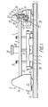
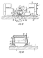
- a scanning device designed according to the invention for ultrasound control of products contains ultrasound transducers 1 (FIG. 1) which are arranged on the product 2 to be checked.
- the ultrasonic transducers 1 are in housings 3 (FIGS. 1 to 3).
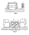
- the ultrasonic transducers 1 (FIG. 4) are pressed onto the surface 4 of the product 2 to be checked with the aid of a pressing device 5 and are fastened to an engine 6 (FIGS. 1 to 3) by means of a suspension device 7.
- the suspension device 7 contains flexible elements 8, a beam 9. two self-adjusting supports 10 and two legs 11.
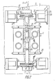
- the flexible elements 8 are arranged above the surface 4 of the product 2 to be checked along the direction of movement of the device specified by the engine 6. In this case, the movement takes place in the direction of the arrows B (FIG. 2) and C along the weld seam 12 on the product 2.
- the flexible elements 8 lie on both sides of the weld seam 12.
- On the flexible elements 8 (FIGS. 1 and 4) they are Ultrasound transducer 1 rigidly attached.
- the self-adjusting supports 10 consist of two parts, one part 13 of which is arranged on the beam 9 and the other part 14 with respect to the first-mentioned part 13 is such that the common displacement of the two parts 13 and 14 with respect to the vibration axis 15 which is common to the self-adjusting supports 10 and is located directly in the vicinity of the surface 4 of the product 2 to be checked.
- the oscillation axis 15 lies directly on the surface 4 of the product 2 and only two self-adjusting supports are trimmed
- three or more self-adjusting supports can be used.
- the legs 11 are kinematically connected to the beam 9 and the engine 6.
- each self-adjusting support 10 is shaped as a ring-shaped element 16, the longitudinal axis of which forms the common axis of oscillation 15 of the two supports arranged at the ends of the beam 9, as shown in FIG 2 can be seen.
- each support 10 is designed in the manner of four rollers 17 fastened to a support plate 18 common to it by means of the screws 19, which are connected to the working surfaces 20 (FIGS. 3, 5) and 21 of the annular Elements 16, are in contact and kinematically connect the beam 9 via the ring-shaped element 16, the support plate 18 and a joint 22 to the handle 11.
- Each housing 3 of the ultrasonic transducer 1 has a sealing cover 29 and a cavity 30 for a ferromagnetic liquid, the use of which for the formation of a stable acoustic contact between the Ultrasonic transducers 1 and the surface 4 of the product 2 to be checked is appropriate.
- the engine 6 (FIG. 2) of the scanning device contains, according to the invention, four housings 31 which are articulated to the ends of the arm 11 by means of axes 32.
- each housing 31 (FIG. 1) there is a magnetic wheel 33 which is fastened to the output shaft of a reduction gear 34 which is fixedly connected to the housing 31.
- An electric motor 35 (FIG. 2) is attached to each reduction gear 34, the output shaft of the electric motor 35 being in engagement with the first stage of the reduction gear 34.
- the engine 6 of the device can also contain two electric motors and reduction gears, which are kinematically connected to the first arm in the direction of movement of the device. This depends on the spatial position of the device as it moves on the surface of the product to be inspected, e.g. when inspecting vertical welds.
- the device designed according to the invention contains a signal transmitter 36 (FIGS. 1 and 2) arranged on the bar 9 for generating signals at the beginning and at the end of the control, as well as sensors 37 for weld seam tracking, which are arranged on the support plates 10 and generate signals which the deviation of the device from the weld 12 during its movement are proportional, and also attached to the joints 22 rotary encoder 38 (Fig. 5) for determining the angle of rotation of the handle 11 with respect to the support plates 18 and one not shown in the drawing and for Distance sensor not belonging to the invention for detecting the distance covered by the device according to the invention.
- a signal transmitter 36 (FIGS. 1 and 2) arranged on the bar 9 for generating signals at the beginning and at the end of the control, as well as sensors 37 for weld seam tracking, which are arranged on the support plates 10 and generate signals which the deviation of the device from the weld 12 during its movement are proportional, and also attached to the joints 22 rotary encoder 38 (Fig. 5) for determining the angle of rotation of the handle
- a defect marker 39 which marks z.3 on the surface of the product. with color to designate existing ones Defects in the product to be checked 2 after the results of the ultrasound control when moving the device.
- Eyelets 40 with openings 41 are provided on the housings 31 (FIG. 5), which are intended for the adjustment of the suspension device 7 before the start of the check.
- products 2 (FIG. 4) made of ferromagnetic materials, e.g. made of steel, contains the pressing device 5 intended for pressing the ultrasonic transducers 1 against the surface 4 of the product to be inspected 5, permanent magnets 42 (poles S, N), which are arranged above the corresponding ultrasonic transducers 1 and fastened on the flexible elements.
- the scanning device according to the invention is carried out according to FIGS. 1 to 6.
- the pressing device 5 In contrast to this facility contains the pressing device 5 (FIGS. 7 and 8) includes a platform 44 which is arranged on the surface 45 of the product 43 on the side opposite to the surface 46 of the product 43 on which the control takes place.
- the curvature of the surface 47 of the platform 44 corresponds to the curvature of the surface 45, the platform 44 being suitable for the automatic repetition of the movement path of the scanning device according to the invention.
- the pressing device 5 also contains permanent magnets 48 (poles S, N) which are arranged on the platform 44 with the poles of the same name to the poles N of the permanent magnets 42 and symmetrical to the latter.
- the automatic repetition of the movement path of the scanning device by the platform 44 is carried out with the aid of the magnetic coupling of the wheels 33 (FIG. 7) of the Engine 6 and the permanent magnets 42 with the permanent magnets 49 and 48 arranged on the platform 44 are achieved, with a secure adhesion of the wheels 33 to the surface 46 of the product 43 to be checked and the pressing of the ultrasonic transducers 1 onto this surface, as well as with Using the self-adjusting wheels 50 (Fig. 9).
- the wheels 50 are mounted on the platform 44 by means of spring-loaded hinges 51 and 45 contact the surface of the product-) ses 43.
- the clearance between the surface 45 to be inspected of the E Nisses rzeug- 43 and the surface of the Magnets 48 and 49 are regulated, which is necessary for overcoming possible obstacles, for example weld roots, through the platform 44 with the magnets 48, 49 fastened thereon and the self-adjusting wheels 50.
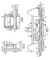
- FIGS. 10 to 14 show an embodiment variant of the scanning device according to the invention, which is constructed similarly to the device according to FIGS. 1 to 6.
- each support 10 is designed as a guide rail 52 with two cylindrical working surfaces 53 and 54 and a flat working surface 55 connecting them.
- the guide rail 52 (FIG. 10) is firmly connected to the beam 9 with the aid of a pair of screws 24.
- each support 10 represents an insert 56 (FIGS. 10, 12 and 13) mechanically connected to the flexible elements 8 with two cylindrical working surfaces 57 (FIGS. 10) and 58 which are connected to one another by a flat working surface 59 , the cylindrical work surfaces 53 and 54 are congruent and touch the latter.
- the longitudinal axes of all cylindrical work surfaces 53 (FIG. 12), 54, 57 and 58 coincide and serve as a common vibration axis 15 for the two self-adjusting supports 10.
- the kinematic connection of the beam 9 (FIG. 12) with the handle 11 is carried out by means of the joints 22 and. 61.
- the bar 9 is provided with joints 62 (FIGS. 10 and 11), which enables the class of the controllable surfaces 4 to be expanded and the fine adjustment of the device to be simplified before the start of the check.
- the sensors 37 intended for tracking the weld seam 12 are fastened to springs 63 which are provided with joints 64, the springs 63 being fastened to the rod 23 by means of the joint 25.
- Limit switches 65 are mounted on these weld seam tracking sensors, which are intended for switching off the sensors 37 for the time, the obstacles for driving over existing obstacles and influencing the display of these sensors 37, for example 3. of transverse welds through which the transmitter 37 is required.
- One of the limit switches 65 also has the task of stopping the movement of the entire device when geometric deviations of the product to be checked (possibly the deviation of the height of the weld seam root) from permissible values are recognized in accordance with the technical requirements for the products 2 and the weld seams 12 will.
- This variant of the scanning device designed according to the invention is preferably to be used in cases when the control on vertical and inclined surfaces 4 of the products 2 is to take place independently of the direction of movement of the device.
- Ferromagnetic shields 66 are attached to the housings 3, which weaken the mutual influence of the magnetic stray fields generated by each permanent magnet 42.
- a support 67 (FIG. 15), which has a surface 68 common to the test pattern 69, and a housing 70 are used for storing and preparing the device according to the invention for work.
- the scanning device for ultrasonic control of products according to the invention works in principle as follows.
- the device designed according to the invention according to FIGS. 1-6 is placed on the surface 68 (FIG. 15) of the base 67 with a test pattern 69.
- the curvature of the surface 68, the thickness and the material of the test pattern 69 must be identical to that of the product 2 to be checked.
- the bar 9 is directed along the direction of movement of the device according to the arrows B (Fig. 2) and C. With the aid of the axes 32 (FIG. 5), the ends of the handle 11 are fastened in the eyelets 40 of the housings 31 of the engine 6 provided with the openings 41 at a predetermined height for the product 2 concerned.
- the rod 23 is fastened to the beam 9 at a distance from the surface 6d, at which the rod 23 with the holders 26 fastened thereon by means of the joints 25 extends freely over the caterpillar surface of the weld seam 12 and can move over the surface 4 of the product 2.
- the tensioning elements 28 FIG.
- the position of the ultrasound transducers 1 with respect to the test pattern 69 is regulated in such a way that the ultrasound transducers 1 cover the entire cross-section of the product 2 to be checked (if necessary, genze Volume of the weld seam 12 and the immediately adjacent zones) pass through, whereupon the ends of the flexible elements 8 are fastened together with the clamping elements 28 with the locking screws 27.
- the cavity 30 (Fig. 4) of the housing 3 is filled with a ferromagnetic fluid to ensure the test pattern 69 by a static b ilen acoustic contact between the ultrasonic transducers 1 and the surface 6d (15 Fig.). Then the functionality of all ultrasonic transducers 1 is checked.
- the pedestal 67 with the device set for the control according to FIGS. 1-6 is brought close to the product 2 to be checked along the direction of movement (the weld seam 12), and the device for which a patent has been applied moves onto the surface 4 of the product 2 to be checked .
- the device moves on the surface 4 of the product 2 as a result of the rotation of the magnetic wheels 33 (FIGS. 1, 5), which adhere securely to the surface 4.
- welds 12 are controlled with the device of FIGS. 1-6, the speed of rotation of the wheels 33 is controlled using the display of the weld tracker 37 and the angle encoder 38.
- the common support plate 18 with the rollers 17 also inclines because the handle 11 and the common support plate 18 are connected to each other by means of the joint 22, but the ring-shaped element 16 of the support 10 which adjusts itself in the front in the direction of movement thereby moves between the rollers 17, and the ultrasonic transducers 1 become in relation to the weld seam 12 not shifted, which is necessary for the ultrasound control of the weld seam 12.
- this obstacle (the transverse weld seam) is overcome by the ultrasonic transducers 1 because they are firmly connected to the flexible elements 8 and constructively have a smooth transition from the attachment point of the flexible elements 8 to the surface of the transducers 1, which touches the surface 4 of the product 2.
- the defect location on the surface of the weld seam is e.g. marked with color, the defect being registered at the same time.
- the device After the end of the control, the device is stopped at the command of the transmitter 36. Under the rear wheels 33 of the device you push the base 67, the device moves on it and stops. The device is switched off, covered with the housing 70 and brought to the next weld seam to be checked.
- the device designed according to the invention is arranged on the base 67 (FIG. 15) with a test pattern 69, the curvature of the surface 68 and the material of the test pattern 69 being those of de controlling product 43 should be identical. Then all preparatory processes take place as for the setting of the device according to FIGS. 1-6 for carrying out the check.
- the height of the platform 44 is regulated from the rear of the pedestal 67 with the aid of the joints 51 (FIG. 7), so that it can block any obstacles such as e.g. Can overcome weld bead.
- the setup also works as described above.
- the device according to FIGS. 10 to 14 is placed on the surface 68 (FIG. 14) of the base 67 with a test pattern 69.
- the curvature of the surface 68, the thickness and the material of the test pattern 69 must be identical to that of the product 2 to be checked.
- the bar 9 is arranged along the direction of movement of the device designated by the arrows B (FIG. 11) and C.
- the holder 26 and the springs 63 are fastened with the aid of the joint 25, and by means of the clamping elements 28 intended for tensioning the flexible elements 8, the position of the ultrasound transducers 1 with respect to the test pattern 69 is regulated so that the ultrasound transducers 1 cover the entire volume to be controlled Product 2 (possibly the entire volume of the weld seam 12 and the zones adjacent to it) pass through, whereupon the ends of the tensioned flexible elements 8 are fastened together with the tensioning elements 28 by means of the locking screws 27.
- the cavity 30 (FIG. 14) of the housing 3 is filled with ferromagnetic liquid in order to ensure stable acoustic contact between the ultrasonic transducers 1 and the surface 68 of the test pattern 69 ensure what you check the functionality of all ultrasonic transducers 1.
- the base 67 with the device set for the control according to FIGS. 10-14 is brought close to the product 2 to be checked, and the device designed according to the invention moves onto the surface 4 of the product 2 to be checked.
- the movement of the device on the surface 4 of the product 2 to be checked takes place as a result of the rotation of the magnetic wheels 33, which adhere securely to the surface 4.
- the rotational movement of the output shafts of the electric motors 35 is transmitted via the reduction gears 34 to the magnetic wheels 33, which are fastened to the output shafts of the reduction gears 34.
- the position of the handle 11 (FIG. 12) with respect to the beam 9 also changes as a result of the joints 22 and 61 present.
- the speed of rotation of the wheels 33 is changed, the device being brought into the position required for the control during its movement on the surface 4 of the product 2 to be checked.
- the limit switch 65 which is arranged on the weld seam tracking transmitter 37 at the front in the direction of movement, generates a signal to shut down the facility.
- the signal from the transmitter 37 causes the output shaft of the electric motor 35 to be braked.
- the handle 11 is pivoted about the joints 22 and the device moves to the weld seam 12.
- the rear wheels 33 move downward from the weld seam 12 to be checked under the influence of the weight of the entire device.
- the seam tracking sensor 37 is also displaced and supplies a command to one of the electric motors 35 , which reduces its number of revolutions and reduces the rotational speed of the wheel 33.
- the handle 11 of the rear wheels 33 in the direction of movement is rotated about the joint 22 and returned to the axis of the weld seam. So the device takes the position necessary for the control and for the movement on the product 2.
- the signal transmitter 36 for the beginning and the end of the control, the ultrasonic transducers 1 are switched on and the entire cross-section to be checked is transmitted through.
- the defect marker 39 makes a mark on the surface 4 of the product 2 to be checked, e.g. with color. After the end of the control, the device is stopped after a signal from the transmitter 36. Under the device you push the pedestal 67 and the device moves on it.
- the arm 11 of the front wheel 33 rotates and lifts the beam 9, its support 10 and the support 10 of the rear wheels 33, which do not separate from the surface 4 of the product 2 to be checked, since the handle 11 of the rear wheels 33 is rotated in the joint 61.
- the position of the magnets 42 on the surface 4 of the product 2 pressed ultrasound transducer 1 does not change, since the beam 9 is pivoted with the guide rail 52 with respect to the insert 56, and the flexible element 8 is stretched on the side of the rear wheels 33, whereby the stroke of the rod 23 with the Brackets 26 compensated.
- the limit switch 65 of the transmitter 37 When the device is moved onto a weld seam which cuts the weld seam 12 to be checked, the limit switch 65 of the transmitter 37, which is at the front in the direction of movement, is rotated and supplies a signal for switching off the transmitter 37 for the time that it is occupied over the weld seam, causing a false indication of one Change in the direction of movement of the device is prevented.
- the signal of the limit switch 65 causes the ultrasound transducer 1 on the same side of the seam 12 to be checked to be switched off when it crosses the crossed weld seam.
- FIGS. 10 to 14 works similarly to the device according to FIGS. 1 to 6.
- the scanning device for the ultrasound control of products ensures greater reliability and credibility of the control and has smaller dimensions, lower weight and a simpler structure of the suspension device. It enables the control of an extended class of products made of both ferromagnetic and non-ferromagnetic materials with different surface curvatures and with different spatial positions of the device.
- the fixed connection of the ultrasonic transducers 1 with the flexible elements 8 located in the immediate vicinity of the product surface and the suspension device gives the additional possibility of removing obstacles on the surface of the product to be checked, for example in the manner of weld beads or metal spatter after welding, regardless of the curvature of the product surface to overcome.
- the permanent magnets the pressing device of the device designed according to the invention allow the use of a ferromagnetic liquid in order to achieve a stable acoustic contact between the ultrasonic transducers and the surface of the product to be checked in different spatial positions and at an ambient temperature of -50 ° C to + 50 ° C.
- a scanning device with a weight of up to 8 kg is used for the on-site inspection of ring weld seams of the pipes of 1420 mm in diameter with a pipe wall thickness of up to 40 mm, the device being operated by one person and the one being checked Butt joint time required is less than 4 min.
- the invention can be used in various industries such as e.g. in mechanical engineering, shipbuilding and nuclear power engineering, in the construction of boilers, natural gas and oil pipelines for the ultrasonic inspection of weld seams and the basic material of ferromagnetic and non-ferromagnetic products with both flat and curved surfaces in different spatial positions of the scanning device, whereby the overcoming of Obstacles can be ensured by the device in the manner of metal spatter after welding or by bead welds with displaced welding edges, as well as the automatic tracking of the weld axis or the automatic movement according to a predetermined movement path.
- industries such as e.g. in mechanical engineering, shipbuilding and nuclear power engineering, in the construction of boilers, natural gas and oil pipelines for the ultrasonic inspection of weld seams and the basic material of ferromagnetic and non-ferromagnetic products with both flat and curved surfaces in different spatial positions of the scanning device, whereby the overcoming of Obstacles can be ensured by the device in the manner
Landscapes
- Physics & Mathematics (AREA)
- Health & Medical Sciences (AREA)
- Life Sciences & Earth Sciences (AREA)
- Chemical & Material Sciences (AREA)
- Analytical Chemistry (AREA)
- Biochemistry (AREA)
- General Health & Medical Sciences (AREA)
- General Physics & Mathematics (AREA)
- Immunology (AREA)
- Pathology (AREA)
- Investigating Or Analyzing Materials By The Use Of Ultrasonic Waves (AREA)
- Nitrogen And Oxygen Or Sulfur-Condensed Heterocyclic Ring Systems (AREA)
Abstract
Dispositif de balayage destiné à l'inspection ultrasonique d'articles, comprenant une unité (7) assurant la suspension des convertisseurs ultrasoniques sur un mécanisme (6), afin de déplacer le dispositif de balayage. L'unité (7) à son tour comprend des éléments souples (8) montés au-dessus de la surface (4) de l'article (2) à inspecter, et portant les convertisseurs ultrasoniques (1) montés dans des logements (3) et fixés rigidement aux éléments souples, de même qu'une poutre (9) située au-dessus des éléments souples (8) et connectée mécaniquement à ces derniers. L'unité (7) comprend également deux supports (10) auto-alignés composés de deux parties: un élément (16) en forme d'anneau et des rouleaux (17), ces deux supports étant orientés l'un par rapport à l'autre de manière qu'ils se déplacent mutuellement autour d'un axe de rotation (15) commun aux supports (10) et situé sur la surface (4) de l'article (2), ainsi que deux bras basculeurs (11) connectés cinématiquement à la poutre (9) et au mécanisme (6), afin de déplacer le dispositif de balayage.
Applications Claiming Priority (2)
| Application Number | Priority Date | Filing Date | Title |
|---|---|---|---|
| SU4336106/28A SU1602193A1 (ru) | 1987-12-10 | 1987-12-10 | Автоматическое сканирующее устройство для ультразвукового контроля сварных швов изделий |
| SU4336106 | 1987-12-10 |
Publications (2)
| Publication Number | Publication Date |
|---|---|
| EP0346473A1 true EP0346473A1 (fr) | 1989-12-20 |
| EP0346473A4 EP0346473A4 (en) | 1991-04-24 |
Family
ID=21339297
Family Applications (1)
| Application Number | Title | Priority Date | Filing Date |
|---|---|---|---|
| EP19880904711 Withdrawn EP0346473A4 (en) | 1987-12-10 | 1988-02-29 | Scanning device for ultrasonic inspection of articles |
Country Status (7)
| Country | Link |
|---|---|
| US (1) | US5062301A (fr) |
| EP (1) | EP0346473A4 (fr) |
| CN (1) | CN1012849B (fr) |
| HU (1) | HU883399D0 (fr) |
| IN (1) | IN168960B (fr) |
| SU (1) | SU1602193A1 (fr) |
| WO (1) | WO1989005451A1 (fr) |
Cited By (5)
| Publication number | Priority date | Publication date | Assignee | Title |
|---|---|---|---|---|
| FR2712091A1 (fr) * | 1993-11-05 | 1995-05-12 | Sepema Sa | Sondeur manuel pour l'inspection cartographique par ultrasons de produits métallurgiques. |
| DE4430604C1 (de) * | 1994-08-16 | 1996-02-22 | Mannesmann Ag | Prüfkopfanordnung |
| WO2013083986A1 (fr) * | 2011-12-07 | 2013-06-13 | Fugro Subsea Services Limited | Dispositif d'inspection |
| WO2020112903A1 (fr) * | 2018-11-29 | 2020-06-04 | Saudi Arabian Oil Company | Véhicule à chenilles présentant une normalisation de sonde automatique |
| US11760127B2 (en) | 2020-12-03 | 2023-09-19 | Saudi Arabian Oil Company | Two-wheel compact inspection crawler with automatic probe normalization |
Families Citing this family (41)
| Publication number | Priority date | Publication date | Assignee | Title |
|---|---|---|---|---|
| DE9110160U1 (de) * | 1990-08-17 | 1991-12-05 | Krautkrämer GmbH & Co, 5030 Hürth | US-Prüfvorrichtung |
| US5404755A (en) * | 1992-04-10 | 1995-04-11 | Olson Engineering, Inc. | Scanning apparatus and method for non-destructive materials evaluation and mapping through use of acoustic waves |
| US5421200A (en) * | 1993-08-26 | 1995-06-06 | General Electric Company | Ultrasonic fixture assembly for holding multiple ultrasonic transducers |
| AU2241695A (en) * | 1994-07-18 | 1996-02-16 | Babcock & Wilcox Co., The | Sensor transport system for flash butt welder |
| US5814731A (en) * | 1997-01-28 | 1998-09-29 | Alexander; Alton Michel | Ultrasonic scanning apparatus for nondestructive site characterization of structures using a planar based acoustic transmitter and receiver in a rolling pond |
| US7142701B2 (en) * | 2003-03-10 | 2006-11-28 | Cranial Technologies, Inc. | Cranial remodeling device manufacturing system |
| US6722202B1 (en) * | 2003-07-16 | 2004-04-20 | The Boeing Company | Method and apparatus for inspecting a structure utilizing magnetically attracted probes |
| US7312454B2 (en) * | 2003-07-16 | 2007-12-25 | The Boeing Company | Non-destructive infrared inspection device |
| US7484413B2 (en) * | 2003-12-12 | 2009-02-03 | The Boeing Company | Remote radius inspection tool for composite joints |
| US7174788B2 (en) * | 2003-12-15 | 2007-02-13 | General Electric Company | Methods and apparatus for rotary machinery inspection |
| US7315609B2 (en) * | 2004-09-16 | 2008-01-01 | The Boeing Company | Real-time X-ray scanner and remote crawler apparatus and method |
| EP1899722A2 (fr) * | 2004-09-16 | 2008-03-19 | The Boeing Company | Appareil et methode d'inspection faisant appel a une attraction magnetique |
| US7050535B2 (en) | 2004-09-16 | 2006-05-23 | The Boeing Company | X-ray laminography inspection system and method |
| US7444876B2 (en) * | 2005-08-26 | 2008-11-04 | The Boeing Company | Rapid prototype integrated linear ultrasonic transducer inspection apparatus, systems, and methods |
| US7617732B2 (en) * | 2005-08-26 | 2009-11-17 | The Boeing Company | Integrated curved linear ultrasonic transducer inspection apparatus, systems, and methods |
| US7640810B2 (en) | 2005-07-11 | 2010-01-05 | The Boeing Company | Ultrasonic inspection apparatus, system, and method |
| US7464596B2 (en) * | 2004-09-24 | 2008-12-16 | The Boeing Company | Integrated ultrasonic inspection probes, systems, and methods for inspection of composite assemblies |
| US7337673B2 (en) * | 2005-07-11 | 2008-03-04 | The Boeing Company | Ultrasonic array probe apparatus, system, and method for traveling over holes and off edges of a structure |
| US7249512B2 (en) * | 2005-01-24 | 2007-07-31 | The Boeing Company | Non-destructive stringer inspection apparatus and method |
| US7313959B2 (en) * | 2005-05-25 | 2008-01-01 | The Boeing Company | Magnetically attracted apparatus, system, and method for remote bondline thickness measurement |
| IT1391237B1 (it) * | 2008-07-14 | 2011-12-01 | Procontrol S R L | Dispositivo semovente, particolarmente per il posizionamento di sonde, in controlli non distruttivi |
| HUE046223T2 (hu) * | 2009-02-27 | 2020-02-28 | Rolls Royce Nuclear Field Services Inc | Ellenõrzõ rendszer és ellenõrzési eljárás mágneses ellenõrzõ jármû alkalmazásával |
| US8347724B2 (en) * | 2009-03-05 | 2013-01-08 | Alstom Technology Ltd | Low profile ultrasound inspection scanner |
| JP5737992B2 (ja) * | 2011-02-18 | 2015-06-17 | 三菱重工業株式会社 | 超音波探傷装置 |
| CN102854248B (zh) * | 2012-09-14 | 2014-07-02 | 桂林电器科学研究院有限公司 | 薄片工件环形焊缝的超声波检测系统 |
| DE102013000685B4 (de) * | 2013-01-11 | 2014-11-13 | Fraunhofer-Gesellschaft zur Förderung der angewandten Forschung e.V. | Mobiles Trägersystem für mindestens ein zur zerstörungsfreien Prüfung ausgebildetes Sensorelement |
| JP6398311B2 (ja) * | 2014-05-16 | 2018-10-03 | 株式会社大林組 | コンクリート検査装置 |
| JP6599273B2 (ja) * | 2016-03-18 | 2019-10-30 | Jxtgエネルギー株式会社 | 溶接部検査装置及び溶接部自動検査装置 |
| JP6837361B2 (ja) * | 2017-03-16 | 2021-03-03 | 日本製鋼所M&E株式会社 | 溶接部位置検知装置、超音波探傷装置、溶接部探傷方法および溶接部位置検知プログラム |
| RU178358U1 (ru) * | 2017-05-10 | 2018-03-30 | Закрытое акционерное общество "Ультракрафт" | Устройство ультразвукового контроля кольцевых сварных швов |
| RU178440U1 (ru) * | 2017-10-31 | 2018-04-04 | Публичное акционерное общество "Транснефть" (ПАО "Транснефть") | Устройство для проведения автоматизированной оценки качества сборки сварного соединения |
| RU177780U1 (ru) * | 2017-11-21 | 2018-03-12 | Публичное акционерное общество "Транснефть" (ПАО "Транснефть") | Устройство для автоматизированного ультразвукового контроля сварных соединений |
| JP6551950B2 (ja) * | 2017-12-26 | 2019-07-31 | 株式会社シーエックスアール | 鋼材検査用走行装置 |
| JP7028080B2 (ja) * | 2018-06-22 | 2022-03-02 | 日本製鉄株式会社 | 管の溶接部の超音波探傷方法 |
| RU192118U1 (ru) * | 2019-06-19 | 2019-09-04 | Закрытое акционерное общество "Ультракрафт" | Искатель кромок листового проката |
| RU195253U1 (ru) * | 2019-07-04 | 2020-01-21 | Федеральное государственное унитарное предприятие "Центральный научно-исследовательский институт конструкционных материалов "Прометей" имени И.В. Горынина Национального исследовательского центра "Курчатовский институт" (НИЦ "Курчатовский институт" - ЦНИИ КМ "Прометей") | Сканирующее устройство для проведения ультразвукового контроля |
| CN110243863B (zh) * | 2019-07-09 | 2020-12-25 | 苏交科集团股份有限公司 | 一种主动激励的焊缝缺陷红外智能检测系统及方法 |
| RU2731165C1 (ru) * | 2019-09-04 | 2020-08-31 | Публичное акционерное общество "Транснефть" (ПАО "Транснефть") | Устройство автоматизированного ультразвукового контроля сварных соединений стенки резервуаров |
| CN110542720B (zh) * | 2019-09-12 | 2024-05-28 | 盛视科技股份有限公司 | 一种非接触式空箱检测机构 |
| RU2757203C1 (ru) * | 2021-01-26 | 2021-10-12 | Публичное акционерное общество "Транснефть" (ПАО "Транснефть") | Способ автоматизированной наружной диагностики трубопровода и автоматизированный диагностический комплекс для его осуществления |
| CN113340203B (zh) * | 2021-07-07 | 2022-11-11 | 哈尔滨理工大学 | 一种激光扫描焊缝装置及扫描方法 |
Family Cites Families (11)
| Publication number | Priority date | Publication date | Assignee | Title |
|---|---|---|---|---|
| US3504534A (en) * | 1967-11-09 | 1970-04-07 | Republic Steel Corp | Tracking assembly for ultrasonic transducers |
| DE1816255C3 (de) * | 1968-12-21 | 1973-11-22 | Hoesch Werke Ag, 4600 Dortmund | Verfahren zur zerstörungsfreien Prüfung von Schweißnahten mittels Ultra schallenergie |
| DE2021278C3 (de) * | 1970-04-30 | 1975-07-03 | Stahlwerke Peine-Salzgitter Ag, 3150 Peine | Vorrichtung zur Ultraschallprüfung von in Vorschubrichtung bewegten metallischen Blechen, Bändern oder Rohren |
| JPS4890583A (fr) * | 1972-03-02 | 1973-11-26 | ||
| US4010636A (en) * | 1975-01-13 | 1977-03-08 | General Electric Company | Vessel examination system |
| SU555333A1 (ru) * | 1975-07-07 | 1977-04-25 | Всесоюзный Проектно-Конструкторский Технологический Институт Атомного Машиностроения И Котлостроения | Устройство дл ультразвукового контрол труб |
| SU1173304A1 (ru) * | 1982-07-05 | 1985-08-15 | Ордена Ленина И Ордена Трудового Красного Знамени Институт Электросварки Им.Е.О.Патона | Установка дл ультразвукового контрол сварных швов изделий |
| SU1128161A1 (ru) * | 1982-10-10 | 1984-12-07 | Научно-производственное объединение "Атомкотломаш" | Сканирующее устройство дл ультразвукового контрол сварных швов изделий |
| US4509369A (en) * | 1983-08-25 | 1985-04-09 | Combustion Engineering, Inc. | Near surface inspection system |
| SU1174851A1 (ru) * | 1984-03-06 | 1985-08-23 | Ленинградский Научно-Исследовательский Институт Мостов | Устройство дл ультразвукового контрол сварных швов |
| SU1320740A1 (ru) * | 1985-09-30 | 1987-06-30 | Ю. А. Дружаев, В. Д. Кор ченко и М. В. Фурман | Устройство дл перемещени ультразвуковых преобразователей |
-
1987
- 1987-12-10 SU SU4336106/28A patent/SU1602193A1/ru active
-
1988
- 1988-02-29 WO PCT/SU1988/000048 patent/WO1989005451A1/fr not_active Ceased
- 1988-02-29 EP EP19880904711 patent/EP0346473A4/ru not_active Withdrawn
- 1988-02-29 US US07/381,395 patent/US5062301A/en not_active Expired - Fee Related
- 1988-02-29 HU HU883399A patent/HU883399D0/hu unknown
- 1988-06-28 IN IN533/CAL/88A patent/IN168960B/en unknown
- 1988-07-26 CN CN88104590.XA patent/CN1012849B/zh not_active Expired
Cited By (8)
| Publication number | Priority date | Publication date | Assignee | Title |
|---|---|---|---|---|
| FR2712091A1 (fr) * | 1993-11-05 | 1995-05-12 | Sepema Sa | Sondeur manuel pour l'inspection cartographique par ultrasons de produits métallurgiques. |
| DE4430604C1 (de) * | 1994-08-16 | 1996-02-22 | Mannesmann Ag | Prüfkopfanordnung |
| EP0701126A2 (fr) | 1994-08-16 | 1996-03-13 | MANNESMANN Aktiengesellschaft | Assemblage de sonde |
| EP0701126A3 (fr) * | 1994-08-16 | 1998-01-21 | MANNESMANN Aktiengesellschaft | Assemblage de sonde |
| WO2013083986A1 (fr) * | 2011-12-07 | 2013-06-13 | Fugro Subsea Services Limited | Dispositif d'inspection |
| WO2020112903A1 (fr) * | 2018-11-29 | 2020-06-04 | Saudi Arabian Oil Company | Véhicule à chenilles présentant une normalisation de sonde automatique |
| US11548577B2 (en) | 2018-11-29 | 2023-01-10 | Saudi Arabian Oil Company | Crawler vehicle with automatic probe normalization |
| US11760127B2 (en) | 2020-12-03 | 2023-09-19 | Saudi Arabian Oil Company | Two-wheel compact inspection crawler with automatic probe normalization |
Also Published As
| Publication number | Publication date |
|---|---|
| SU1602193A1 (ru) | 1994-04-30 |
| CN1033484A (zh) | 1989-06-21 |
| US5062301A (en) | 1991-11-05 |
| CN1012849B (zh) | 1991-06-12 |
| HUT53962A (en) | 1990-12-28 |
| EP0346473A4 (en) | 1991-04-24 |
| WO1989005451A1 (fr) | 1989-06-15 |
| IN168960B (fr) | 1991-07-27 |
| HU883399D0 (en) | 1990-12-28 |
Similar Documents
| Publication | Publication Date | Title |
|---|---|---|
| EP0346473A1 (fr) | Dispositif de balayage destine a l'inspection ultrasonique d'articles | |
| DE69101586T2 (de) | Bewegbares Unterwasserprüfsystem. | |
| DE60012781T2 (de) | Verfahren zur erfassung des dynamischen verhaltens eines fahrzeugs auf einem prüfstand | |
| DE102020208961B3 (de) | Verfahren zur Ausrichtung eines Roboterarms | |
| WO2016156039A1 (fr) | Ensemble de soudage servant à assembler de manière durable un premier élément de forme tubulaire à un deuxième élément | |
| DE10051706A1 (de) | Vorrichtung zur Lagerung eines optischen Elementes | |
| DE102016216388A1 (de) | System und Verfahren zum Trennen eines rohrförmigen Bauteils | |
| DE202015101427U1 (de) | Montageeinrichtung | |
| DE102017210213A1 (de) | Greifer mit einem Sensor an einem Getriebegliedlager des Greifers | |
| DE1698157B2 (de) | Verfahren und vorrichtung zum positionieren eines kraftfahrzeuges auf einem simulations-versuchsstand | |
| DE102005061618B4 (de) | System und Verfahren zur Ausrichtungs- und Lagekontrolle eines Roboterwerkzeugs | |
| DE2636246A1 (de) | Verfahren und vorrichtung zum ultraschallpruefen der stutzenfelder eines reaktordruckbehaelters | |
| DE69130575T2 (de) | Gerät zum Positionieren und Richten von Einkristall-Barren | |
| DE69305899T2 (de) | Vorrichtung zur automatischen Bestimmung der Restspannung in einer Felge eines Radsatzes für Schienen, bzw. Gleisfahrzeuge | |
| EP0359140A2 (fr) | Dispositif pour tester l'adhérence par tirage | |
| DE3050664C2 (de) | Verfahren zur Bewegung eines Punktes in eine Lage,deren Koordinaten in einem orthogonalen System vorgegeben sind und Vorrichtung zur Druchf}hrung dieses Verfahrens | |
| DE102012103548A1 (de) | Verfahren und Vorrichtung zum Ausrichten eines Werkzeugs sowie Bearbeitungsstation und Messeinrichtung | |
| DE29622132U1 (de) | Meßvorrichtung zur Ermittlung von Massenverhältnissen | |
| DE3246220A1 (de) | Verfahren zum automatischen zuordnen und verbinden zweier koerper, insbesondere einer radfelge und einer radnabe | |
| DE102007055453B4 (de) | Vorrichtung und Verfahren zum Laserschweißen | |
| DE2642481A1 (de) | Verfahren und vorrichtung zur vollautomatischen schweissnahtfindung und -folgung bei der zerstoerungsfreien ultraschallpruefung geschweisster rohre | |
| DE102014104031B4 (de) | Verfahren zur Onlinebahnführung für einen Roboter, Verfahren zur Überwachung einer Applikationsstruktur sowie Sensor zum Durchführen dieser Verfahren | |
| DE3407780A1 (de) | Spann- und wendevorrichtung | |
| DE2557338A1 (de) | Verfahren zur positionierung eines auf einem bohrarm montierten gesteinsbohrapparats und vorrichtung zur durchfuehrung des verfahrens | |
| EP4614132A1 (fr) | Dispositif de contrôle pour le contrôle automatisé d'un cordon de soudure et procédé de contrôle d'un cordon de soudure |
Legal Events
| Date | Code | Title | Description |
|---|---|---|---|
| PUAI | Public reference made under article 153(3) epc to a published international application that has entered the european phase |
Free format text: ORIGINAL CODE: 0009012 |
|
| 17P | Request for examination filed |
Effective date: 19890825 |
|
| AK | Designated contracting states |
Kind code of ref document: A1 Designated state(s): DE FR GB IT SE |
|
| A4 | Supplementary search report drawn up and despatched |
Effective date: 19910306 |
|
| AK | Designated contracting states |
Kind code of ref document: A4 Designated state(s): DE FR GB IT SE |
|
| RHK1 | Main classification (correction) |
Ipc: G01N 29/00 |
|
| STAA | Information on the status of an ep patent application or granted ep patent |
Free format text: STATUS: THE APPLICATION IS DEEMED TO BE WITHDRAWN |
|
| 18D | Application deemed to be withdrawn |
Effective date: 19920903 |