EP0346312B1 - Verfahren zum Entwässern von nassem, feinkörnigem Gut mittels Druckgas - Google Patents
Verfahren zum Entwässern von nassem, feinkörnigem Gut mittels Druckgas Download PDFInfo
- Publication number
- EP0346312B1 EP0346312B1 EP89850183A EP89850183A EP0346312B1 EP 0346312 B1 EP0346312 B1 EP 0346312B1 EP 89850183 A EP89850183 A EP 89850183A EP 89850183 A EP89850183 A EP 89850183A EP 0346312 B1 EP0346312 B1 EP 0346312B1
- Authority
- EP
- European Patent Office
- Prior art keywords
- gas
- pressure
- particle collection
- pressure difference
- dewatering
- Prior art date
- Legal status (The legal status is an assumption and is not a legal conclusion. Google has not performed a legal analysis and makes no representation as to the accuracy of the status listed.)
- Expired - Lifetime
Links
- 239000002245 particle Substances 0.000 title claims description 36
- 238000000034 method Methods 0.000 title claims description 28
- XLYOFNOQVPJJNP-UHFFFAOYSA-N water Substances O XLYOFNOQVPJJNP-UHFFFAOYSA-N 0.000 title claims description 14
- 230000035515 penetration Effects 0.000 claims description 14
- 238000012544 monitoring process Methods 0.000 claims 1
- 239000012065 filter cake Substances 0.000 description 9
- 230000008569 process Effects 0.000 description 9
- 239000007788 liquid Substances 0.000 description 8
- 238000007664 blowing Methods 0.000 description 6
- 238000005265 energy consumption Methods 0.000 description 4
- 239000000725 suspension Substances 0.000 description 3
- 239000004744 fabric Substances 0.000 description 2
- 229910052500 inorganic mineral Inorganic materials 0.000 description 2
- 239000000463 material Substances 0.000 description 2
- 239000011707 mineral Substances 0.000 description 2
- 238000005086 pumping Methods 0.000 description 2
- 229920006395 saturated elastomer Polymers 0.000 description 2
- 239000007787 solid Substances 0.000 description 2
- 238000005054 agglomeration Methods 0.000 description 1
- 230000002776 aggregation Effects 0.000 description 1
- 239000012141 concentrate Substances 0.000 description 1
- 238000010276 construction Methods 0.000 description 1
- 238000007796 conventional method Methods 0.000 description 1
- 230000001419 dependent effect Effects 0.000 description 1
- 238000010586 diagram Methods 0.000 description 1
- 238000001035 drying Methods 0.000 description 1
- 238000005516 engineering process Methods 0.000 description 1
- 239000000835 fiber Substances 0.000 description 1
- 238000001914 filtration Methods 0.000 description 1
- 238000010438 heat treatment Methods 0.000 description 1
- 229910052595 hematite Inorganic materials 0.000 description 1
- 239000011019 hematite Substances 0.000 description 1
- LIKBJVNGSGBSGK-UHFFFAOYSA-N iron(3+);oxygen(2-) Chemical compound [O-2].[O-2].[O-2].[Fe+3].[Fe+3] LIKBJVNGSGBSGK-UHFFFAOYSA-N 0.000 description 1
- 230000007246 mechanism Effects 0.000 description 1
- 239000012528 membrane Substances 0.000 description 1
- 230000002093 peripheral effect Effects 0.000 description 1
- 239000011148 porous material Substances 0.000 description 1
- 230000000135 prohibitive effect Effects 0.000 description 1
- 235000008001 rakum palm Nutrition 0.000 description 1
- 230000009467 reduction Effects 0.000 description 1
- 238000000926 separation method Methods 0.000 description 1
- 238000005406 washing Methods 0.000 description 1
Images
Classifications
-
- B—PERFORMING OPERATIONS; TRANSPORTING
- B01—PHYSICAL OR CHEMICAL PROCESSES OR APPARATUS IN GENERAL
- B01D—SEPARATION
- B01D43/00—Separating particles from liquids, or liquids from solids, otherwise than by sedimentation or filtration
-
- F—MECHANICAL ENGINEERING; LIGHTING; HEATING; WEAPONS; BLASTING
- F26—DRYING
- F26B—DRYING SOLID MATERIALS OR OBJECTS BY REMOVING LIQUID THEREFROM
- F26B5/00—Drying solid materials or objects by processes not involving the application of heat
- F26B5/14—Drying solid materials or objects by processes not involving the application of heat by applying pressure, e.g. wringing; by brushing; by wiping
Definitions
- the present invention relates to a method for dewatering water-containing particle collections in which at least one of a possible multiple of dewatering stages is effected with the aid of gas to which a pressure difference is imparted through and across the particle collection.
- Water-containing particle collections such as mineral suspensions and fibre suspensions
- Water-containing particle collections are often dewatered by first mechanically pumping the particle collection onto a filtering medium and/or by pressing said collection against said medium under high pressure, such as to form a filter cake from which water is then removed under the influence of gas under pressure.
- Dewatering can either be accomplished by employing a vacuum and/or by using a pressurized gas, said gas normally being compressed air.
- the filter cake is subjected to a pressure difference which consists, in principle, of the sum of the low pressure on the suction side and the high pressure on the pressure side.
- the dewatering process is effected through the influence of this pressure difference in three successive phases, mainly a first penetration phase, which is commenced by subjecting fully saturated filter cake to pressurized gas on one side thereof, and is terminated when the gas breaks through the filter cake (penetration) and thus exits from the other side of said cake.
- a first penetration phase which is commenced by subjecting fully saturated filter cake to pressurized gas on one side thereof, and is terminated when the gas breaks through the filter cake (penetration) and thus exits from the other side of said cake.
- water present in the cake is simply displaced forwardly by the advancing gas front.
- the drainage phase the gas flows through the filter cake while maintaining a pressure difference within the cake, the water in this case being forced to move in the same direction as the gas.
- This phase will terminate when the water capillary forces are in equilibrium with the gas pressure prevailing locally within the filter cake, with a subsequent decrease in water flow. When this state is reached, further water can only be removed by vapourizing water into the passing gas flow
- dewatering mechanism is employed in several processes that are applied industrially for the purpose of dewatering particle collections in three phases or stages.
- dewatering is effected in at least one of the process stages with the aid of a gas to which there is imparted a pressure difference through and across the particle collection.
- the final lowering of the moisture content of the particle collection is achieved by compressed-air blowing.
- the novel and inventive method is based on the principle of effecting pressurized-gas dewatering of the particle collection or agglomeration in essentially one single phase, namely the penetration phase, instead of in all three phases of the conventional method described briefly above. It has been found, very surprisingly, that dewatering in one single phase can be effected in a manner such as to render further dewatering phases unnecessary, therewith utilizing the energy input to an optimum.
- dewatering is accomplished with a high gas pressure or large pressure difference of not less than 0.1 MPa (1 atm ) over a well defined time period, namely the time taken for the gas to penetrate, i.e. pass through, the particle collection (the filter cake).
- the time taken for the gas to penetrate a particle collection is a highly complex magnitude which is contingent, inter alia, on the thickness or depth extension of the particle collection (the filter cake), the pressure applied, the porosity of the filter cake, the specific surface area and density of the particles, the viscosity of the water and the proportion of solids in the particle collection.
- the pressure difference is engendered by first compressing a given, known gas volume to a pressure which will provide the predetermined pressure difference through and across the particle collection, while taking into account possible pressure losses and an optionally applied sub-ambient pressure on the suction side, whereafter the compressed gas is allowed to act freely on the particle collection.
- the simplest method of achieving this in practice is by pumping gas, from a small compressor, into a pressure vessel until the desired pressure is obtained, and then opening a valve so as to allow the gas to exit forcibly onto the particle collection for as long as it takes the gas volume to expand.
- a gas flow of constant predetermined pressure for instance taken from a compressed air mains, is allowed to act on the particle collection until penetration occurs.
- the time at which penetration occurs can be followed-up and indicated in several ways, although it is preferred to measure the flow of gas through the particle collection continuously, and to cut-off the gas flow automatically when penetration is indicated.
- these two embodiments of the inventive method can be combined in different ways.
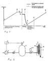
- Figure 1 is a principle diagram of the gas pressure prevailing in the pressure vessel,through and across the particle collection, as a function of the state of a working cycle
- Figure 2 illustrates the principle construction of apparatus for carrying out the preferred embodiment.
- gas normally air
- the capacity of the compressor 1 is preferably chosen so that a desired maximum pressure P b is obtained in the pressure vessel 2 prior to the blowing phase of the working cycle, time point c in Figure 1. In this way, minor variations in the duration of the working cycle will not affect the maximum pressure P b , and therewith the end result. Consequently, the compressor 1 is relieved of load at point b ( Figure 1) at which the pressure P b has been reached, e.g. through a compressor control circuit 4 which is activated by a control signal produced by a manometer 3, back leakage of gas through the pressure-relieved compressor 1 being prevented by a check valve 5.
- the volume of the pressure vessel 2 is selected so that the useable part of the enclosed compressed gas at pressure P b has an energy content which corresponds to the energy required to expel liquid.
- a valve 6 is opened by an auxiliary operating device 6a, such that gas will flow into the high pressure side 8 of a chamber arrangement 7 of the kind described and illustrated in the aforementioned publication SE-A-453 726.
- the gas pressure will fall from pressure P b to pressure P n , as a result of the increase in the available gas volume, said gas pressure P n being chosen so that the requisite expulsion of liquid will have been achieved upon completion of the penetration of the gas and associated lowering of the pressure, time point e.
- the gas on the high pressure side 8 can only expand further, while displacing liquid from the initially liquid-saturated particle collection 9.
- the displaced liquid exits into the low pressure side 10 of the chamber 7, and is led away from said low pressure side through a drainage pipe 11.
- the gas reaches the low pressure side 10 at time point d, wherewith the rate of flow of the gas increases drastically while displacing flow-prohibiting liquid from the major part of the pore system in the particle collection 9.
- the gas pressure will now fall quickly across the particle collection 9 and the through flowing gas will assist in draining liquid from the particle collection 9 and the chamber 7.
- the valve 6 is closed at time point e (alternatively at pressure P m ) and the compressor 1 is switched to its working state, so that the gas pressure will again rise to pressure P b during the time points e-b1.
- the chamber 7 has been opened and and its contents discharged and optional washing of the filter medium on fabric cloth has been carried out, the chamber 7 has been reclosed and again filled, accompanied by optional subsequent pressing of the particle collection through a membrane.
Landscapes
- Engineering & Computer Science (AREA)
- Chemical & Material Sciences (AREA)
- Chemical Kinetics & Catalysis (AREA)
- Health & Medical Sciences (AREA)
- Life Sciences & Earth Sciences (AREA)
- Molecular Biology (AREA)
- Mechanical Engineering (AREA)
- General Engineering & Computer Science (AREA)
- Processing Of Solid Wastes (AREA)
- Drying Of Solid Materials (AREA)
- Filtering Materials (AREA)
- Drying Of Gases (AREA)
Claims (6)
- Verfahren zur Entwässerung wasserhaltiger Teilchenansammlungen, bei dem eine Entwässerungsstufe mit Hilfe von Gas bewirkt wird, dem ein vorbestimmter Druckunterschied von nicht weniger als 0,1 MPa (1 atm) in der und quer zu der Teilchenansammlung erteilt wird, dadurch gekennzeichnet, daß die Enwässerungsstufe in der Weise bewirkt wird, daß man den Druckunterschied über eine Zeitdauer hält, welche die Zeit nicht wesentlich übersteigt, die erforderlich ist, um eine Gasdurchdringung der damit entwässerten Teilchenanasammlung zu erreichen.
- Verfahren nach Anspruch 1, dadurch gekennzeichnet, daß man den vorbestimmten Druckunterschied und die Zeitdauer steuert, indem man zunächst ein vorbestimmtes Gasvolumen auf einen vorbestimmten Druck komprimiert, welcher in Beziehung zu dem Druckunterschied steht, und dann das komprimierte Gasvolumen auf die Teilchenansammlung einwirken läßt.
- Verfahren nach Anspruch 1, dadurch gekennzeichnet, daß der vorbestimmte Druckunterschied erzeugt wir, indem man einen Gasstrom von konstantem vorbestimmtem Druck in Bezug auf den Druckunterschied auf die Teilchenansammlung einwirken läßt, bis die Durchdringung erfolgt ist.
- Verfahren nach Anspruch 2, dadurch gekennzeichnet, daß man das Gas mit Hilfe eines Kompressors komprimiert, der so arbeitet, daß er Gas einem Druckbehälter von vorbestimmtem Volumen zuführt, bis der vorbestimmte Druck erreicht ist.
- Verfahren nach den Ansprüchen 1 bis 3, dadurch gekennzeichnet, daß der Durchdringungszeitpunkt durch kontinuierliches Überwachen des Gasstromes angezeigt wird.
- Verfahren nach den Ansprüchen 1 bis 5, dadurch gekennzeichnet, daß man den Gasstrom unterbricht, wenn der Durchdringungszeitpunkt angezeigt wird.
Applications Claiming Priority (2)
| Application Number | Priority Date | Filing Date | Title |
|---|---|---|---|
| SE8802110A SE464171B (sv) | 1988-06-07 | 1988-06-07 | Foerfarande foer gastrycksavvattning av vatteninnehaallande partikelsamling |
| SE8802110 | 1988-06-07 |
Publications (2)
| Publication Number | Publication Date |
|---|---|
| EP0346312A1 EP0346312A1 (de) | 1989-12-13 |
| EP0346312B1 true EP0346312B1 (de) | 1993-08-18 |
Family
ID=20372537
Family Applications (1)
| Application Number | Title | Priority Date | Filing Date |
|---|---|---|---|
| EP89850183A Expired - Lifetime EP0346312B1 (de) | 1988-06-07 | 1989-06-05 | Verfahren zum Entwässern von nassem, feinkörnigem Gut mittels Druckgas |
Country Status (9)
| Country | Link |
|---|---|
| US (1) | US4986008A (de) |
| EP (1) | EP0346312B1 (de) |
| AU (1) | AU614126B2 (de) |
| BR (1) | BR8902638A (de) |
| CA (1) | CA1325605C (de) |
| DE (1) | DE68908487T2 (de) |
| DK (1) | DK172237B1 (de) |
| ES (1) | ES2045555T3 (de) |
| SE (1) | SE464171B (de) |
Families Citing this family (4)
| Publication number | Priority date | Publication date | Assignee | Title |
|---|---|---|---|---|
| SE465656B (sv) * | 1990-02-22 | 1991-10-14 | Sala International Ab | Foerfarande foer avvattning av partikelsamlingar |
| US5331747A (en) * | 1992-03-04 | 1994-07-26 | General Electric Company | Hydraulic test apparatus and method for stator in electrical generator |
| WO2006031406A1 (en) * | 2004-09-13 | 2006-03-23 | Benesi Steve C | High-efficiency slurry filtration apparatus and method |
| DE102008010184B4 (de) * | 2008-02-20 | 2015-12-10 | Jürgen Kuhn und Michael Kuhn Grundstücksverwaltungs- und verpachtungs GbR (Vertretungsberechtigter Gesellschafter der GbR: Michael Kuhn, 74746 Höpfingen) | Pressenvorrichtung, insbesondere für eine Waschpresse, und Waschpressenvorrichtung mit einer derartigen Pressenvorrichtung |
Family Cites Families (4)
| Publication number | Priority date | Publication date | Assignee | Title |
|---|---|---|---|---|
| GB1571504A (en) * | 1976-01-29 | 1980-07-16 | English Clays Lovering Pochin | Separation of solids and liquids |
| EP0088174B1 (de) * | 1980-08-06 | 1987-06-16 | William Bradshaw | Trocknungsverfahren und -Vorrichtung |
| US4664813A (en) * | 1985-09-26 | 1987-05-12 | Schneider John R | Method and apparatus for drying sludge using movable plates |
| SE453726B (sv) * | 1986-07-10 | 1988-02-29 | Sala International Ab | Forfarande och anordning vid pressfilter |
-
1988
- 1988-06-07 SE SE8802110A patent/SE464171B/sv not_active IP Right Cessation
-
1989
- 1989-05-05 AU AU34065/89A patent/AU614126B2/en not_active Ceased
- 1989-05-09 CA CA000599101A patent/CA1325605C/en not_active Expired - Fee Related
- 1989-06-05 EP EP89850183A patent/EP0346312B1/de not_active Expired - Lifetime
- 1989-06-05 DE DE89850183T patent/DE68908487T2/de not_active Expired - Fee Related
- 1989-06-05 ES ES89850183T patent/ES2045555T3/es not_active Expired - Lifetime
- 1989-06-06 DK DK274989A patent/DK172237B1/da not_active IP Right Cessation
- 1989-06-06 US US07/362,011 patent/US4986008A/en not_active Expired - Fee Related
- 1989-06-06 BR BR898902638A patent/BR8902638A/pt not_active IP Right Cessation
Also Published As
| Publication number | Publication date |
|---|---|
| US4986008A (en) | 1991-01-22 |
| AU614126B2 (en) | 1991-08-22 |
| BR8902638A (pt) | 1990-01-23 |
| DE68908487T2 (de) | 1993-12-09 |
| DK274989A (da) | 1989-12-08 |
| DK172237B1 (da) | 1998-02-02 |
| CA1325605C (en) | 1993-12-28 |
| ES2045555T3 (es) | 1994-01-16 |
| EP0346312A1 (de) | 1989-12-13 |
| DK274989D0 (da) | 1989-06-06 |
| SE464171B (sv) | 1991-03-18 |
| SE8802110D0 (sv) | 1988-06-07 |
| SE8802110L (sv) | 1989-12-08 |
| AU3406589A (en) | 1989-12-14 |
| DE68908487D1 (de) | 1993-09-23 |
Similar Documents
| Publication | Publication Date | Title |
|---|---|---|
| US4116831A (en) | Separation of solids and liquids | |
| EP0346312B1 (de) | Verfahren zum Entwässern von nassem, feinkörnigem Gut mittels Druckgas | |
| WO1981002528A1 (en) | Dewatering system | |
| US3502210A (en) | Filtering process and system for carrying the process into effect | |
| US5133879A (en) | Filtering procedure using a box filter and removing cake therefrom | |
| US4622144A (en) | Pressure filter apparatus | |
| WO1992022374A1 (en) | Control system | |
| KR20130018279A (ko) | 고체 액체 분리 방법 | |
| AU2017428404B2 (en) | A method for operating a filter press and a filter press | |
| Carleton et al. | Dewatering of cakes | |
| FI89874C (fi) | Foerfarande foer avskiljning av fasta aemnen ur dessa rikligt innehaollande uppslamningar | |
| JP7617360B2 (ja) | フィルタープレスのエアブロー方法 | |
| SU1715384A1 (ru) | Способ обезвоживани скоагулированного осадка станции аэрации | |
| CA1201071A (en) | Pressure filter method and apparatus | |
| JPS6443314A (en) | Controlling device for sludge dehydrator | |
| JPH0472600B2 (de) | ||
| RU1808004C (ru) | Способ обезвоживани дисперсных капилл рнопористых материалов | |
| JPS54129571A (en) | Filter press attached with vacuum process | |
| SU1711974A1 (ru) | Способ переработки отходов углеобогащени | |
| JPH0256123B2 (de) | ||
| JP3255474B2 (ja) | 濾過濃縮装置及び濾過濃縮方法 | |
| JPS59159299A (ja) | 汚泥の圧搾脱水装置 | |
| JPH0515708A (ja) | フイルタープレスの運転方法 | |
| JPH0471607A (ja) | 加圧濾過機のフリージング現象防止方法 | |
| JPH0724402U (ja) | スラッジ脱水濾過装置 |
Legal Events
| Date | Code | Title | Description |
|---|---|---|---|
| PUAI | Public reference made under article 153(3) epc to a published international application that has entered the european phase |
Free format text: ORIGINAL CODE: 0009012 |
|
| AK | Designated contracting states |
Kind code of ref document: A1 Designated state(s): BE DE ES FR GB IT |
|
| 17P | Request for examination filed |
Effective date: 19900530 |
|
| 17Q | First examination report despatched |
Effective date: 19911106 |
|
| GRAA | (expected) grant |
Free format text: ORIGINAL CODE: 0009210 |
|
| AK | Designated contracting states |
Kind code of ref document: B1 Designated state(s): BE DE ES FR GB IT |
|
| REF | Corresponds to: |
Ref document number: 68908487 Country of ref document: DE Date of ref document: 19930923 |
|
| ET | Fr: translation filed | ||
| ITF | It: translation for a ep patent filed | ||
| REG | Reference to a national code |
Ref country code: ES Ref legal event code: FG2A Ref document number: 2045555 Country of ref document: ES Kind code of ref document: T3 |
|
| PLBE | No opposition filed within time limit |
Free format text: ORIGINAL CODE: 0009261 |
|
| STAA | Information on the status of an ep patent application or granted ep patent |
Free format text: STATUS: NO OPPOSITION FILED WITHIN TIME LIMIT |
|
| 26N | No opposition filed | ||
| REG | Reference to a national code |
Ref country code: GB Ref legal event code: IF02 |
|
| PGFP | Annual fee paid to national office [announced via postgrant information from national office to epo] |
Ref country code: GB Payment date: 20020605 Year of fee payment: 14 |
|
| PGFP | Annual fee paid to national office [announced via postgrant information from national office to epo] |
Ref country code: FR Payment date: 20020610 Year of fee payment: 14 |
|
| PGFP | Annual fee paid to national office [announced via postgrant information from national office to epo] |
Ref country code: DE Payment date: 20020612 Year of fee payment: 14 |
|
| PGFP | Annual fee paid to national office [announced via postgrant information from national office to epo] |
Ref country code: ES Payment date: 20020618 Year of fee payment: 14 |
|
| PGFP | Annual fee paid to national office [announced via postgrant information from national office to epo] |
Ref country code: BE Payment date: 20020821 Year of fee payment: 14 |
|
| PG25 | Lapsed in a contracting state [announced via postgrant information from national office to epo] |
Ref country code: GB Free format text: LAPSE BECAUSE OF NON-PAYMENT OF DUE FEES Effective date: 20030605 |
|
| PG25 | Lapsed in a contracting state [announced via postgrant information from national office to epo] |
Ref country code: ES Free format text: LAPSE BECAUSE OF NON-PAYMENT OF DUE FEES Effective date: 20030606 |
|
| PG25 | Lapsed in a contracting state [announced via postgrant information from national office to epo] |
Ref country code: BE Free format text: LAPSE BECAUSE OF NON-PAYMENT OF DUE FEES Effective date: 20030630 |
|
| BERE | Be: lapsed |
Owner name: *SALA INTERNATIONAL A.B. Effective date: 20030630 |
|
| PG25 | Lapsed in a contracting state [announced via postgrant information from national office to epo] |
Ref country code: DE Free format text: LAPSE BECAUSE OF NON-PAYMENT OF DUE FEES Effective date: 20040101 |
|
| GBPC | Gb: european patent ceased through non-payment of renewal fee |
Effective date: 20030605 |
|
| PG25 | Lapsed in a contracting state [announced via postgrant information from national office to epo] |
Ref country code: FR Free format text: LAPSE BECAUSE OF NON-PAYMENT OF DUE FEES Effective date: 20040227 |
|
| REG | Reference to a national code |
Ref country code: FR Ref legal event code: ST |
|
| REG | Reference to a national code |
Ref country code: ES Ref legal event code: FD2A Effective date: 20030606 |
|
| PG25 | Lapsed in a contracting state [announced via postgrant information from national office to epo] |
Ref country code: IT Free format text: LAPSE BECAUSE OF NON-PAYMENT OF DUE FEES;WARNING: LAPSES OF ITALIAN PATENTS WITH EFFECTIVE DATE BEFORE 2007 MAY HAVE OCCURRED AT ANY TIME BEFORE 2007. THE CORRECT EFFECTIVE DATE MAY BE DIFFERENT FROM THE ONE RECORDED. Effective date: 20050605 |