EP0345734A2 - Verfahren und Vorrichtung zum kontinuierlichen Schmieden von Stahl-Strangguss - Google Patents
Verfahren und Vorrichtung zum kontinuierlichen Schmieden von Stahl-Strangguss Download PDFInfo
- Publication number
- EP0345734A2 EP0345734A2 EP89110233A EP89110233A EP0345734A2 EP 0345734 A2 EP0345734 A2 EP 0345734A2 EP 89110233 A EP89110233 A EP 89110233A EP 89110233 A EP89110233 A EP 89110233A EP 0345734 A2 EP0345734 A2 EP 0345734A2
- Authority
- EP
- European Patent Office
- Prior art keywords
- cast steel
- compression
- anvil
- forging
- anvils
- Prior art date
- Legal status (The legal status is an assumption and is not a legal conclusion. Google has not performed a legal analysis and makes no representation as to the accuracy of the status listed.)
- Granted
Links
- 229910001208 Crucible steel Inorganic materials 0.000 title claims abstract description 122
- 238000007906 compression Methods 0.000 title claims abstract description 116
- 230000006835 compression Effects 0.000 title claims abstract description 116
- 238000005242 forging Methods 0.000 title claims abstract description 90
- 238000000034 method Methods 0.000 title claims abstract description 30
- 230000009467 reduction Effects 0.000 claims abstract description 18
- 238000009749 continuous casting Methods 0.000 claims abstract description 14
- 238000005266 casting Methods 0.000 claims abstract description 10
- 230000008569 process Effects 0.000 claims description 5
- 238000005204 segregation Methods 0.000 description 27
- 229910000831 Steel Inorganic materials 0.000 description 18
- 238000007711 solidification Methods 0.000 description 18
- 230000008023 solidification Effects 0.000 description 18
- 239000010959 steel Substances 0.000 description 18
- 239000007790 solid phase Substances 0.000 description 15
- 239000007791 liquid phase Substances 0.000 description 12
- OKTJSMMVPCPJKN-UHFFFAOYSA-N Carbon Chemical compound [C] OKTJSMMVPCPJKN-UHFFFAOYSA-N 0.000 description 5
- 229910052799 carbon Inorganic materials 0.000 description 5
- 239000012071 phase Substances 0.000 description 5
- 238000005336 cracking Methods 0.000 description 4
- 229910052717 sulfur Inorganic materials 0.000 description 4
- 230000008901 benefit Effects 0.000 description 3
- 238000011156 evaluation Methods 0.000 description 3
- 230000006872 improvement Effects 0.000 description 3
- 238000012423 maintenance Methods 0.000 description 3
- 238000003756 stirring Methods 0.000 description 3
- XEEYBQQBJWHFJM-UHFFFAOYSA-N Iron Chemical compound [Fe] XEEYBQQBJWHFJM-UHFFFAOYSA-N 0.000 description 2
- NINIDFKCEFEMDL-UHFFFAOYSA-N Sulfur Chemical compound [S] NINIDFKCEFEMDL-UHFFFAOYSA-N 0.000 description 2
- 239000013078 crystal Substances 0.000 description 2
- 230000007547 defect Effects 0.000 description 2
- 238000010586 diagram Methods 0.000 description 2
- 238000006073 displacement reaction Methods 0.000 description 2
- 230000000694 effects Effects 0.000 description 2
- 230000007246 mechanism Effects 0.000 description 2
- 239000002184 metal Substances 0.000 description 2
- 229910052751 metal Inorganic materials 0.000 description 2
- 102220342298 rs777367316 Human genes 0.000 description 2
- 102220097517 rs876659265 Human genes 0.000 description 2
- 238000006467 substitution reaction Methods 0.000 description 2
- 239000011593 sulfur Substances 0.000 description 2
- 230000002159 abnormal effect Effects 0.000 description 1
- 230000009471 action Effects 0.000 description 1
- 230000002411 adverse Effects 0.000 description 1
- 238000009833 condensation Methods 0.000 description 1
- 230000005494 condensation Effects 0.000 description 1
- 238000001816 cooling Methods 0.000 description 1
- 238000013461 design Methods 0.000 description 1
- 238000002474 experimental method Methods 0.000 description 1
- BHEPBYXIRTUNPN-UHFFFAOYSA-N hydridophosphorus(.) (triplet) Chemical compound [PH] BHEPBYXIRTUNPN-UHFFFAOYSA-N 0.000 description 1
- 229910052742 iron Inorganic materials 0.000 description 1
- 238000003475 lamination Methods 0.000 description 1
- 238000004519 manufacturing process Methods 0.000 description 1
- 238000012986 modification Methods 0.000 description 1
- 230000004048 modification Effects 0.000 description 1
- 238000009497 press forging Methods 0.000 description 1
- 230000002265 prevention Effects 0.000 description 1
- 230000008707 rearrangement Effects 0.000 description 1
- 230000004044 response Effects 0.000 description 1
- 238000012360 testing method Methods 0.000 description 1
- XLYOFNOQVPJJNP-UHFFFAOYSA-N water Substances O XLYOFNOQVPJJNP-UHFFFAOYSA-N 0.000 description 1
Images


Classifications
-
- B—PERFORMING OPERATIONS; TRANSPORTING
- B21—MECHANICAL METAL-WORKING WITHOUT ESSENTIALLY REMOVING MATERIAL; PUNCHING METAL
- B21D—WORKING OR PROCESSING OF SHEET METAL OR METAL TUBES, RODS OR PROFILES WITHOUT ESSENTIALLY REMOVING MATERIAL; PUNCHING METAL
- B21D1/00—Straightening, restoring form or removing local distortions of sheet metal or specific articles made therefrom; Stretching sheet metal combined with rolling
- B21D1/02—Straightening, restoring form or removing local distortions of sheet metal or specific articles made therefrom; Stretching sheet metal combined with rolling by rollers
-
- B—PERFORMING OPERATIONS; TRANSPORTING
- B21—MECHANICAL METAL-WORKING WITHOUT ESSENTIALLY REMOVING MATERIAL; PUNCHING METAL
- B21J—FORGING; HAMMERING; PRESSING METAL; RIVETING; FORGE FURNACES
- B21J1/00—Preparing metal stock or similar ancillary operations prior, during or post forging, e.g. heating or cooling
- B21J1/04—Shaping in the rough solely by forging or pressing
-
- B—PERFORMING OPERATIONS; TRANSPORTING
- B21—MECHANICAL METAL-WORKING WITHOUT ESSENTIALLY REMOVING MATERIAL; PUNCHING METAL
- B21B—ROLLING OF METAL
- B21B15/00—Arrangements for performing additional metal-working operations specially combined with or arranged in, or specially adapted for use in connection with, metal-rolling mills
- B21B15/0035—Forging or pressing devices as units
-
- B—PERFORMING OPERATIONS; TRANSPORTING
- B22—CASTING; POWDER METALLURGY
- B22D—CASTING OF METALS; CASTING OF OTHER SUBSTANCES BY THE SAME PROCESSES OR DEVICES
- B22D11/00—Continuous casting of metals, i.e. casting in indefinite lengths
- B22D11/12—Accessories for subsequent treating or working cast stock in situ
- B22D11/1206—Accessories for subsequent treating or working cast stock in situ for plastic shaping of strands
-
- B—PERFORMING OPERATIONS; TRANSPORTING
- B21—MECHANICAL METAL-WORKING WITHOUT ESSENTIALLY REMOVING MATERIAL; PUNCHING METAL
- B21B—ROLLING OF METAL
- B21B1/00—Metal-rolling methods or mills for making semi-finished products of solid or profiled cross-section; Sequence of operations in milling trains; Layout of rolling-mill plant, e.g. grouping of stands; Succession of passes or of sectional pass alternations
- B21B1/02—Metal-rolling methods or mills for making semi-finished products of solid or profiled cross-section; Sequence of operations in milling trains; Layout of rolling-mill plant, e.g. grouping of stands; Succession of passes or of sectional pass alternations for rolling heavy work, e.g. ingots, slabs, blooms, or billets, in which the cross-sectional form is unimportant ; Rolling combined with forging or pressing
- B21B1/024—Forging or pressing
-
- B—PERFORMING OPERATIONS; TRANSPORTING
- B21—MECHANICAL METAL-WORKING WITHOUT ESSENTIALLY REMOVING MATERIAL; PUNCHING METAL
- B21B—ROLLING OF METAL
- B21B1/00—Metal-rolling methods or mills for making semi-finished products of solid or profiled cross-section; Sequence of operations in milling trains; Layout of rolling-mill plant, e.g. grouping of stands; Succession of passes or of sectional pass alternations
- B21B1/46—Metal-rolling methods or mills for making semi-finished products of solid or profiled cross-section; Sequence of operations in milling trains; Layout of rolling-mill plant, e.g. grouping of stands; Succession of passes or of sectional pass alternations for rolling metal immediately subsequent to continuous casting
- B21B1/463—Metal-rolling methods or mills for making semi-finished products of solid or profiled cross-section; Sequence of operations in milling trains; Layout of rolling-mill plant, e.g. grouping of stands; Succession of passes or of sectional pass alternations for rolling metal immediately subsequent to continuous casting in a continuous process, i.e. the cast not being cut before rolling
-
- Y—GENERAL TAGGING OF NEW TECHNOLOGICAL DEVELOPMENTS; GENERAL TAGGING OF CROSS-SECTIONAL TECHNOLOGIES SPANNING OVER SEVERAL SECTIONS OF THE IPC; TECHNICAL SUBJECTS COVERED BY FORMER USPC CROSS-REFERENCE ART COLLECTIONS [XRACs] AND DIGESTS
- Y10—TECHNICAL SUBJECTS COVERED BY FORMER USPC
- Y10T—TECHNICAL SUBJECTS COVERED BY FORMER US CLASSIFICATION
- Y10T29/00—Metal working
- Y10T29/49—Method of mechanical manufacture
- Y10T29/4998—Combined manufacture including applying or shaping of fluent material
- Y10T29/49988—Metal casting
Definitions
- the present invention relates to a method and an apparatus for continuous compression forging cast steel derived from the continuous casting process. More specifically, the present invention relates to a method and an apparatus for improving the internal quality of cast steel, and, more particularly, for overcoming defects in casting such as central segregation and center porosity by performing effective compression forging at temperatures below the solidification point of the cast steel obtained by continuous casting.
- Segregation in cast steel is considered acceptable since the condensed molten steel is sucked in the front end portion of the solidified region of the cast steel and is allowed to remain with normal segregation in the central portion of the thickness of the cast steel.
- the above-described suction of the condensed molten steel can be realized due to: solidification shrinkage of continuously cast steel at the front portion of the solidified region thereof, and a vacuum suction force generated due to bulging of the solidified shell.
- the interface between the solidified steel and the still molten portion can protect against cracking and negative segregation can be satisfactorily prevented from generation compared with the heavy compression method such as the inline-reduction method in which rollers are used, causing even the semi-macro segregation can be overcome.
- the heavy compression method such as the inline-reduction method in which rollers are used, causing even the semi-macro segregation can be overcome.
- the compression is insufficient in the region of the cast steel in which the unsolidified portion is in a great proportion, cracks can be formed on the interface between the solidified steel and the still molten portion. If the compression is performed excessively, intense negative segregation can be generated in the central portion of the cast steel.
- any effect cannot be obtained from this compression.
- the most suitable compressing conditions have not been as yet established to be performed.
- a group including the inventor of the present invention has disclosed a method in Japanese Patent Laid-Open No. 60-82257 in which a compression-forging anvil is used for the purpose of compressing the cast steel near completion of the solidification of the same.
- a hydraulic press system has been usually used as a continuously compression-forging machine employed in each countermeasures taken against the above-described central segregation of the continuously cast steel.
- a method is disclosed in Japanese Patent Laid-Open No. 63-49400 in which an integrally formed frame of a "Floating Type" includes upper and lower anvils so that compression is equally applied from the upper portion by using a single hydraulic cylinder.
- a scissors method is disclosed in Japanese Patent Laid-Open No. 61-222663 in which a boosting mechanism such as lever is used.
- the conventional devices of the hydraulic type need a great size hydraulic pressure source and pipes to be provided, causing cost required for institution and the load for maintenance becomes too large.
- the life of the pump and the same of the hydraulic control valve is shortened to two or three years, and the involved noise can exceed 100 phons.
- An object of the present invention is to provide a method and an apparatus which are able to overcome the conventional problems which have arisen when cast steel obtained by continuous casting is subjected to compression forging at a point near the solidification point of the cast steel, that is, in the final solidification region formed by an unsolidified portion and the completely solidified portion, which method and apparatus are advantageously used for manufacturing cast steel of an excellent quality.
- the cast steel is compressed with said anvil at a compressing cycle which meets the following conditions: where t: the compressing cycle (sec) ⁇ : the overall thickness reduction (mm) V c : the casting speed (mm/sec) D: the cast steel thickness (mm) before compression forging ⁇ : the inclination angle (°) with respect to the flat surface of the anvil.
- ⁇ the coefficient of friction between the anvil and the cast steel (3) A method of continuous compression forging by using an anvil with a mean width which meets the requirements a ⁇ B-1.36D + 1.64 ⁇ D-80 + 0.182 ⁇
- a the anvil mean width (mm)
- B the cast steel width (mm) before compression forging
- ⁇ the overall thickness reduction (mm)
- D the cast steel thickness (mm) before compression forging
- the present invention effectively prevents forming of internal cracks during a continuous compression forging process for the continuous cast steel by arranging a proper shape of the anvil employed and by setting the compression forging conditions.
- the unsolidified portion 1b of the cast steel 1 is compressed when the portion corresponding to the thickness of the liquid phase thereof is compressed. Assuming that the thickness of the unsolidified portion immediately below the anvil 2 is d, and that the solid phase ratio at the axis portion of the cast steel is f so , the thickness dl corresponding to the liquid phase region can be obtained as follows since the mean solid phase ratio is
- the solidification ratio (f so ) of the axial portion of the cast steel is defined by an index expressing the position of the temperature of the center portion of the cast steel between a liquid phase line temperature and a solid phase line temperature, this temperature being defined in accordance with the type of steel, wherein a solidification ratio of 1.0 means a fact that the temperature is within the solidification phase temperature region, while 0.5 means a fact that the same is within the intermediate region between the liquid phase line temperature and the solid phase line temperature.
- the interface between the solidified steel and the still molten portion is at the position at which the solidification rate is 100 %, that is at the position of the solidification phase line temperature, at which no liquid phase is present, but all are in the solid phase.
- the phase is not gradually changed from the solid phase to the liquid phase, but a coexist region of the solid phase and the liquid phase is present, wherein the solid phase rate is 100 % at the position in the solid phase line temperature, while the liquid phase rate is 100 % at the position in the liquid phase line temperature.
- the thickness dl corresponding to the liquid phase region can be expressed as follows when converted into a thickness d e corresponding to the liquid phase that is compressed by one compression forging: wherein OA ⁇ ⁇ 0 needs to be subjected to a compression forging corresponding to d e in l b . Therefore, the following relationship holds in one compression forging at a feeding pitch l c : and (1) into (2) gives
- ⁇ the overall thickness reduction (mm)
- V c the casting speed (mm/sec)
- t the compression forging cycle ⁇ time (sec) of one cycle
- l a the contact length (mm) of the slope of the anvil in the direction L corresponding to the overall thickness reduction
- ⁇ l c the feeding pitch (mm) in one compression forging cycle l b : (l a - l c ) (mm)
- the front point O when the ensuing compression forging starts needs to be on the portion rather adjacent to the unsolidified region compared to A ⁇ in order to prevent generation of internal cracks, it is necessary for the front end point O′ at the completion point of the compression to be positioned forward at least by l c than A ⁇ . That is, it is necessary for preventing generation of internal cracks to have a thickness d e of the liquid phase in the unsolidified portion which is positioned forward by l c by the overall thickness reduction caused by one forced compression, and thereby to have the interface between the solidified steel and the still molten portion move ahead. ⁇ e ⁇ d e (5)
- the thus-obtained equation represents the conditions required for the compressing cycle to prevent generation of internal cracks.
- the thickness d of the unsolidified phase with respect to the flow of the cast steel 1 to be compressed needs to be within the following range: 1.2 ⁇ D- 80 ⁇ d ⁇ 10 ⁇ D- 80 (7)
- the solid phase ratio f so at the central portion of the cast steel needs to be within the following range: 0.5 ⁇ f so ⁇ 0.9 (8)
- the inclination angle ⁇ of the above-described anvil 2 needs to be determined to be smaller than a frictional angle tan ⁇ 1 ⁇ at the forging surface for the purpose of preventing slippage on the surface of the cast steel 1 when this cast steel 1 is compressed.
- the conditions required to be realized on the cross-section C need to be arranged in such a manner that the width of the anvil 2 is determined as to have the compression force of the anvil 2 applied substantially equally to the unsolidified width b of the cast steel 1 as shown in Fig. 2, where the width of the anvil 2 is arranged to be the mean width a of the portion to be compressed.
- the anvil width a with respect to the overall thickness reduction ⁇ /4 will represent the anvil width.
- symbol c of Fig. 2 represents the width of the flat portion of the anvil.
- equation (13) can be rearranged to be: a ⁇ B - D + 1.2 ⁇ D - 80 - (D - 1.2 ⁇ D - 80 - ⁇ 2 tan 20°, therefore, a ⁇ B - 1.36D + 1.64 ⁇ D - 80 + 0.182 ⁇ (14)
- the anvils are preferably provided with a position adjusting means capable of individually adjusting the overall thickness reduction. More particularly, it is preferable for the anvils to be provided with a position adjusting means comprising a hydraulic cylinder and a stopper for restricting the stroke of this cylinder.
- FIGs. 9(a) and 9(b) One structure of a compression forging apparatus according to the present invention is schematically shown in Figs. 9(a) and 9(b).
- Reference numeral 1 represents cast steel drawn out from a mold for performing the continuous casting
- 2a and 2b represent anvils. These anvils 2a and 2b vertically hold the pass line of the cast steel 1 and continuously compression-forge the final solidified region of the cast steel 1 by their movement toward and away from each other.
- Reference numeral 13 represents a frame having an inlet port 13a through which the cast steel 1 is introduced, and in which either of the two anvils 2a or 2b is disposed therein (the anvil 2b is so disposed here).
- Reference numeral 14 represents a slider capable of vertically and reciprocally moving along a sliding surface 13c formed in the frame 13, this slider 14 being provided with the other anvil 2a at the front end surface thereof.
- Reference numeral 15 represents a crank shaft which acts to make the anvils 2a and 2b move toward or away from each other. Thus, the frame 13 and the slider 14 are hung from the crank shaft 15 with the corresponding links 13b and 14a.
- the crank shaft 15 supporting the frame 13 and the slider 14 in a pendulum manner is revolved by a motor or the like via, for example, a decelerator
- the anvils 2a and 2b connected to the links 13b and 14a via the frame 13 and the slider 14 repeat the opening and closing movement centering the pass line since the links 13b and 14a are made eccentric with respect to the rotational axis of the crank shaft 15 by distances e1 and e2.
- the cast steel 1 is continuously subjected to compression forging by the relative movement of the anvils 2a and 2b coming closer and away from each other.
- Fig. 10 is a view which illustrates the relationship between the locus of an anvil, for example, the anvil 2, and the feed of the cast steel 1 when the crank shaft 15 is rotated in a direction designated by an arrow E.
- This feed is illustrated as classified into a case where the drawing speed of the cast steel 1 is raised and a case where the same is lowered (it is the same if the rotational speed of the crank shaft 15 is varied and the drawing speed of the cast steel 1 is set to a constant speed) with rotational speed of the crank shaft 15 set to a constant speed.
- the anvil 2a moves from F to F′ when the drawing speed is a relatively high speed, while the same moves from G to G′ when the same is a relatively low speed.
- the overall thickness reduction becomes the same in either case.
- the path followed by the apparatus body is described as the above-described locus, but the cast steel 1 is moved horizontally due to the drawing. There arises a fear that an excessive force might be applied to the cast steel 1 or the apparatus during the compression forging.
- the follow-up distance of the apparatus is practically limited to several tens mm in practice, such problem can be overcome by securing the length of the pendulum at least 3 m.
- the height displacement is limited within the clearance of the apparatus, causing no problem.
- the compression forging apparatus which has been moved as a result of the drawing of the cast steel 1 at the time of performing compression forging can be quickly restored to its original position by providing a hydraulic means 16 (Figs. 9(a) and 13(b)), for example, a hydraulic cylinder, for the frame 13.
- a hydraulic means 16 for example, a hydraulic cylinder
- the anvils 2a and 2b can be used as a relief mechanism from abnormal loads if they are secured, as a position-adjusting means, to the frame 13 and the slider 14 via, for example, the hydraulic cylinder 17.
- the cast steel 1 can be made to pass through the gap between the anvils 2a and 2b when the gap is widened in an emergency.
- an advantage can be obtained in that the work for changing the size of the cast steel 1 can be readily performed.
- a simple and mechanical adjusting means can be realized without any necessity of providing an expensive hydraulic servo system by arranging, as shown in Fig. 12, the structure in such a manner that the above-described position adjusting means comprises an electric or manual abutting stopper 18 and hydraulic cylinders 17a and 17b, the stopper 18 comprising the nut 18a, a screw 18b, and an absorbing member 18c.
- the position adjusting means of the lower anvil 2b can be easily broken due to heat, water, or scale generated during operation, and its maintenance is difficult to be conducted.
- the hydraulic pressure cylinder 17 which serves as the position adjusting means needs, as shown in Figs. 13 (a) and (b), to be disposed above the main frame body 13 (upper than the crank shaft) and as well the main frame body 13 needs to be connected to the crank shaft 15 with the anvil 2b supported via this position adjusting means.
- the above-described devices shown in Fig. 9 are respectively provided to correspond to strands, and are hung from one crank shaft so as to realize a compressing cycle with which the start of the compression forging for each of the strands cannot become the same, for example, so as to make the phase difference 180° in a case of 2-strand, 120° in a case of 3-strand, and 90° in a case of 4-strand.
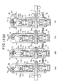
- Figs. 13(a) and 13(b) are views which schematically illustrate the case of a 4-strand continuous caster.
- Fig. 14 is a view which illustrates an operation diagram of the crank shaft 15 of Figs. 13(a) and (b).
- the compression forging apparatus is disposed above the pass line of the crank shaft for hanging, and the motor and decelerator for rotating this crank shaft, it may disposed below the pass line if there is sufficient space.
- the results are shown in Fig. 6.
- the axis of ordinate of this drawing represents the index (reference is set to 1) obtained by dividing the overall length of the internal cracks observed in a sulfur print test carried out upon the sample of the 600 mm long cross-section L after compression forging by the overall length of the allowable limit of the internal cracks of the sample.
- the compression cycles 16.3 sec and 15.2 sec for preventing internal cracks obtained from equations (9) and (6) are shown.
- these compression cycles approximate to 18 sec and are smaller than this 18 sec, it is apparent that they can serve as the evaluation equation.
- the internal cracks of the cast steel when the same is compression forged can be prevented.
- the internal defects such as central segregations can be improved.
- a significant improvement can be obtained with respect to the product manufactured by the conventional continuous casting.
- the apparatus according to the present invention displays significant advantages with respect to the conventional apparatus. Therefore, a significantly smooth operation can be achieved according to the present invention.
Landscapes
- Engineering & Computer Science (AREA)
- Mechanical Engineering (AREA)
- Forging (AREA)
- Metal Rolling (AREA)
Applications Claiming Priority (4)
| Application Number | Priority Date | Filing Date | Title |
|---|---|---|---|
| JP13847288 | 1988-06-07 | ||
| JP138472/88 | 1988-06-07 | ||
| JP163822/88 | 1988-06-30 | ||
| JP16382288A JPH0628788B2 (ja) | 1988-06-30 | 1988-06-30 | 連続鋳造における鋳片の連続鍛圧方法 |
Publications (3)
| Publication Number | Publication Date |
|---|---|
| EP0345734A2 true EP0345734A2 (de) | 1989-12-13 |
| EP0345734A3 EP0345734A3 (en) | 1990-03-07 |
| EP0345734B1 EP0345734B1 (de) | 1992-01-22 |
Family
ID=26471483
Family Applications (1)
| Application Number | Title | Priority Date | Filing Date |
|---|---|---|---|
| EP89110233A Expired - Lifetime EP0345734B1 (de) | 1988-06-07 | 1989-06-06 | Verfahren und Vorrichtung zum kontinuierlichen Schmieden von Stahl-Strangguss |
Country Status (7)
| Country | Link |
|---|---|
| US (1) | US4930207A (de) |
| EP (1) | EP0345734B1 (de) |
| KR (1) | KR920000807B1 (de) |
| AU (1) | AU611804B2 (de) |
| BR (1) | BR8902678A (de) |
| CA (1) | CA1309280C (de) |
| DE (1) | DE68900750D1 (de) |
Cited By (2)
| Publication number | Priority date | Publication date | Assignee | Title |
|---|---|---|---|---|
| EP0528051A1 (de) * | 1991-02-26 | 1993-02-24 | Kawasaki Steel Corporation | Kontinuierliches schmiedeverfahren für gussstrange |
| US20220362833A1 (en) * | 2019-12-23 | 2022-11-17 | Gfm Gmbh | Method for machining a metal cast strand of round cross-section by reducing the cross-section in the final solidification region |
Families Citing this family (6)
| Publication number | Priority date | Publication date | Assignee | Title |
|---|---|---|---|---|
| AT407230B (de) * | 1996-02-20 | 2001-01-25 | Gfm Gmbh | Verfahren zum herstellen von metallenem stabmaterial |
| IT1288870B1 (it) * | 1996-03-25 | 1998-09-25 | Danieli Off Mecc | Dispositivo di compattazione laterale per bramme |
| EP1145777B1 (de) * | 1999-03-10 | 2005-06-08 | Ishikawajima-Harima Heavy Industries Co., Ltd. | Verfahren zum herstellen von warmgewalztem stahlblech |
| EP1046443A1 (de) * | 1999-04-23 | 2000-10-25 | Franz Dr.-Ing. Gütlbauer | Verfahren und Vorrichtung zur Formung von Metallsträngen |
| CN102814443B (zh) * | 2012-07-30 | 2014-12-17 | 江阴南工锻造有限公司 | 一种矩形坯料的极限锻造法 |
| CN102814438B (zh) * | 2012-07-30 | 2014-12-17 | 江阴南工锻造有限公司 | 一种改善齿轮件钢坯金相组织的锻造工艺 |
Citations (5)
| Publication number | Priority date | Publication date | Assignee | Title |
|---|---|---|---|---|
| GB509226A (en) * | 1937-11-29 | 1939-07-12 | Eumuco Ag Fuer Maschinenbau | Improvements in power hammers |
| GB955119A (en) * | 1961-07-25 | 1964-04-15 | B & S Massey & Sons Ltd | Improvements in counter blow hammers |
| DE2228593A1 (de) * | 1972-06-12 | 1974-01-10 | Kh Awiazionnij I | Hochgeschwindigkeitsmaschine zum druckverformen von metallen |
| US3921429A (en) * | 1974-04-11 | 1975-11-25 | Tadeusz Sendzimir | Process and apparatus for modifying the cross section of a slab |
| JPS6082257A (ja) * | 1983-10-07 | 1985-05-10 | Kawasaki Steel Corp | 連続鋳造における連続鍛圧法 |
Family Cites Families (10)
| Publication number | Priority date | Publication date | Assignee | Title |
|---|---|---|---|---|
| JPS5240826B2 (de) * | 1972-05-12 | 1977-10-14 | ||
| JPS5916541B2 (ja) * | 1975-10-31 | 1984-04-16 | 日本鋼管株式会社 | 鋼の連続鋳造方法 |
| JPS58186882A (ja) * | 1982-04-27 | 1983-10-31 | Toshiba Corp | 手書き文字入力装置 |
| JPS59202145A (ja) * | 1983-05-02 | 1984-11-15 | Nippon Steel Corp | 鋼の連続鋳造方法 |
| JPS60148651A (ja) * | 1984-01-13 | 1985-08-05 | Kawasaki Steel Corp | 連続鋳造機 |
| EP0157575B2 (de) * | 1984-03-29 | 1996-04-10 | Kawasaki Steel Corporation | Verfahren zur Verringerung der Breite von Platten durch Pressen und Presse hierzu |
| JPH0244619B2 (ja) * | 1985-03-28 | 1990-10-04 | Kawasaki Steel Co | Renchusutorandonotanatsusochi |
| JPS62124044A (ja) * | 1985-11-22 | 1987-06-05 | Kawasaki Steel Corp | 熱間スラブの幅圧下プレス方法及び装置 |
| JPS6349400A (ja) * | 1986-08-19 | 1988-03-02 | Fujitsu Ltd | 電子制御プレス加工機 |
| JPH0682257A (ja) * | 1992-08-31 | 1994-03-22 | Japan Aviation Electron Ind Ltd | 光干渉角速度計 |
-
1989
- 1989-05-24 US US07/356,125 patent/US4930207A/en not_active Expired - Fee Related
- 1989-05-25 AU AU35207/89A patent/AU611804B2/en not_active Ceased
- 1989-06-02 CA CA000601608A patent/CA1309280C/en not_active Expired - Lifetime
- 1989-06-06 EP EP89110233A patent/EP0345734B1/de not_active Expired - Lifetime
- 1989-06-06 DE DE8989110233T patent/DE68900750D1/de not_active Expired - Fee Related
- 1989-06-07 BR BR898902678A patent/BR8902678A/pt not_active IP Right Cessation
- 1989-06-07 KR KR1019890007892A patent/KR920000807B1/ko not_active IP Right Cessation
Patent Citations (5)
| Publication number | Priority date | Publication date | Assignee | Title |
|---|---|---|---|---|
| GB509226A (en) * | 1937-11-29 | 1939-07-12 | Eumuco Ag Fuer Maschinenbau | Improvements in power hammers |
| GB955119A (en) * | 1961-07-25 | 1964-04-15 | B & S Massey & Sons Ltd | Improvements in counter blow hammers |
| DE2228593A1 (de) * | 1972-06-12 | 1974-01-10 | Kh Awiazionnij I | Hochgeschwindigkeitsmaschine zum druckverformen von metallen |
| US3921429A (en) * | 1974-04-11 | 1975-11-25 | Tadeusz Sendzimir | Process and apparatus for modifying the cross section of a slab |
| JPS6082257A (ja) * | 1983-10-07 | 1985-05-10 | Kawasaki Steel Corp | 連続鋳造における連続鍛圧法 |
Non-Patent Citations (1)
| Title |
|---|
| PATENT ABSTRACTS OF JAPAN, vol. 9, no. 226 (M-412)[1949], 12th September 1985; & JP-A-60 082 257 (KAWASAKI SEITETSU K.K.) 10-05-1985 * |
Cited By (3)
| Publication number | Priority date | Publication date | Assignee | Title |
|---|---|---|---|---|
| EP0528051A1 (de) * | 1991-02-26 | 1993-02-24 | Kawasaki Steel Corporation | Kontinuierliches schmiedeverfahren für gussstrange |
| EP0528051A4 (de) * | 1991-02-26 | 1995-04-19 | Kawasaki Steel Co | |
| US20220362833A1 (en) * | 2019-12-23 | 2022-11-17 | Gfm Gmbh | Method for machining a metal cast strand of round cross-section by reducing the cross-section in the final solidification region |
Also Published As
| Publication number | Publication date |
|---|---|
| EP0345734B1 (de) | 1992-01-22 |
| EP0345734A3 (en) | 1990-03-07 |
| US4930207A (en) | 1990-06-05 |
| AU611804B2 (en) | 1991-06-20 |
| CA1309280C (en) | 1992-10-27 |
| KR920000807B1 (ko) | 1992-01-23 |
| BR8902678A (pt) | 1990-01-23 |
| AU3520789A (en) | 1989-12-14 |
| DE68900750D1 (de) | 1992-03-05 |
| KR910000256A (ko) | 1991-01-29 |
Similar Documents
| Publication | Publication Date | Title |
|---|---|---|
| EP0345734B1 (de) | Verfahren und Vorrichtung zum kontinuierlichen Schmieden von Stahl-Strangguss | |
| JPH11179505A (ja) | 凝固中に板厚減少を行う高速連続鋳造装置のための方法及び装置 | |
| RU2094139C1 (ru) | Способ изготовления непрерывнолитых стальных заготовок и устройство для его осуществления | |
| AU626048B2 (en) | Apparatus for continuous compression forging of continuously cast steel | |
| KR960004422B1 (ko) | 연속 주조시 주강의 연속 압하 단조 방법 및 장치 | |
| JPH08164460A (ja) | 内質の良好な連続鋳造鋳片の製造方法 | |
| EP0263725B1 (de) | Verfahren und Vorrichtung zum kontinuierlichen Druckschmieden von Stranggussstahl | |
| JP3055453B2 (ja) | 連続鋳造方法 | |
| JP4232867B2 (ja) | 鋼帯の連続鋳造方法 | |
| JPH0366057B2 (de) | ||
| JPH02160151A (ja) | 連鋳機内における鋳片形状成形方法 | |
| KR100418985B1 (ko) | 열간 자유단조 강괴 압하방법 | |
| US5083604A (en) | Method for improving internal center segregation and center porosity of continuously cast strand | |
| JPH0244619B2 (ja) | Renchusutorandonotanatsusochi | |
| JPS6082257A (ja) | 連続鋳造における連続鍛圧法 | |
| JP2986928B2 (ja) | 連続鋳造における鋳片ストランドの連続鍛圧方法 | |
| JPH01273657A (ja) | 連鋳ストランドの鍛圧装置 | |
| JP3108263B2 (ja) | 連続鋳造における鋳片ストランドの連続鍛圧方法 | |
| JP2945060B2 (ja) | センターポロシティのない連鋳鋳片の製造方法 | |
| JPH06106316A (ja) | 板厚中心部のじん性および内質に優れた極厚鋼板の製造方法 | |
| JP2915544B2 (ja) | 連続鋳造における鋳片ストランドの連続鍛圧方法 | |
| JPS58184052A (ja) | 連続鋳造機における圧縮制御装置 | |
| JPH06218510A (ja) | 鋼の連続鋳造方法 | |
| JPH08257714A (ja) | 連続鋳造装置 | |
| JPH0515957A (ja) | 連続鋳造における鋳片ストランドの連続鍛圧方法 |
Legal Events
| Date | Code | Title | Description |
|---|---|---|---|
| PUAI | Public reference made under article 153(3) epc to a published international application that has entered the european phase |
Free format text: ORIGINAL CODE: 0009012 |
|
| AK | Designated contracting states |
Kind code of ref document: A2 Designated state(s): BE DE FR GB IT NL SE |
|
| PUAL | Search report despatched |
Free format text: ORIGINAL CODE: 0009013 |
|
| AK | Designated contracting states |
Kind code of ref document: A3 Designated state(s): BE DE FR GB IT NL SE |
|
| 17P | Request for examination filed |
Effective date: 19900220 |
|
| 17Q | First examination report despatched |
Effective date: 19910311 |
|
| GRAA | (expected) grant |
Free format text: ORIGINAL CODE: 0009210 |
|
| AK | Designated contracting states |
Kind code of ref document: B1 Designated state(s): BE DE FR GB IT NL SE |
|
| ITF | It: translation for a ep patent filed |
Owner name: PROPRIA PROTEZIONE PROPR. IND. |
|
| ET | Fr: translation filed | ||
| REF | Corresponds to: |
Ref document number: 68900750 Country of ref document: DE Date of ref document: 19920305 |
|
| PLBE | No opposition filed within time limit |
Free format text: ORIGINAL CODE: 0009261 |
|
| STAA | Information on the status of an ep patent application or granted ep patent |
Free format text: STATUS: NO OPPOSITION FILED WITHIN TIME LIMIT |
|
| 26N | No opposition filed | ||
| EAL | Se: european patent in force in sweden |
Ref document number: 89110233.7 |
|
| PGFP | Annual fee paid to national office [announced via postgrant information from national office to epo] |
Ref country code: GB Payment date: 19990602 Year of fee payment: 11 |
|
| PGFP | Annual fee paid to national office [announced via postgrant information from national office to epo] |
Ref country code: SE Payment date: 19990607 Year of fee payment: 11 Ref country code: DE Payment date: 19990607 Year of fee payment: 11 |
|
| PGFP | Annual fee paid to national office [announced via postgrant information from national office to epo] |
Ref country code: FR Payment date: 19990610 Year of fee payment: 11 |
|
| PGFP | Annual fee paid to national office [announced via postgrant information from national office to epo] |
Ref country code: NL Payment date: 19990628 Year of fee payment: 11 |
|
| PGFP | Annual fee paid to national office [announced via postgrant information from national office to epo] |
Ref country code: BE Payment date: 19990819 Year of fee payment: 11 |
|
| PG25 | Lapsed in a contracting state [announced via postgrant information from national office to epo] |
Ref country code: GB Free format text: LAPSE BECAUSE OF NON-PAYMENT OF DUE FEES Effective date: 20000606 |
|
| PG25 | Lapsed in a contracting state [announced via postgrant information from national office to epo] |
Ref country code: SE Free format text: LAPSE BECAUSE OF NON-PAYMENT OF DUE FEES Effective date: 20000607 |
|
| PG25 | Lapsed in a contracting state [announced via postgrant information from national office to epo] |
Ref country code: BE Free format text: LAPSE BECAUSE OF NON-PAYMENT OF DUE FEES Effective date: 20000630 |
|
| BERE | Be: lapsed |
Owner name: KAWASAKI STEEL CORP. Effective date: 20000630 |
|
| PG25 | Lapsed in a contracting state [announced via postgrant information from national office to epo] |
Ref country code: NL Free format text: LAPSE BECAUSE OF NON-PAYMENT OF DUE FEES Effective date: 20010101 |
|
| GBPC | Gb: european patent ceased through non-payment of renewal fee |
Effective date: 20000606 |
|
| EUG | Se: european patent has lapsed |
Ref document number: 89110233.7 |
|
| PG25 | Lapsed in a contracting state [announced via postgrant information from national office to epo] |
Ref country code: FR Free format text: LAPSE BECAUSE OF NON-PAYMENT OF DUE FEES Effective date: 20010228 |
|
| NLV4 | Nl: lapsed or anulled due to non-payment of the annual fee |
Effective date: 20010101 |
|
| REG | Reference to a national code |
Ref country code: FR Ref legal event code: ST |
|
| PG25 | Lapsed in a contracting state [announced via postgrant information from national office to epo] |
Ref country code: DE Free format text: LAPSE BECAUSE OF NON-PAYMENT OF DUE FEES Effective date: 20010403 |
|
| PG25 | Lapsed in a contracting state [announced via postgrant information from national office to epo] |
Ref country code: IT Free format text: LAPSE BECAUSE OF NON-PAYMENT OF DUE FEES;WARNING: LAPSES OF ITALIAN PATENTS WITH EFFECTIVE DATE BEFORE 2007 MAY HAVE OCCURRED AT ANY TIME BEFORE 2007. THE CORRECT EFFECTIVE DATE MAY BE DIFFERENT FROM THE ONE RECORDED. Effective date: 20050606 |