EP0345709A1 - Châssis pour bogie de véhicule ferroviaire - Google Patents
Châssis pour bogie de véhicule ferroviaire Download PDFInfo
- Publication number
- EP0345709A1 EP0345709A1 EP89110160A EP89110160A EP0345709A1 EP 0345709 A1 EP0345709 A1 EP 0345709A1 EP 89110160 A EP89110160 A EP 89110160A EP 89110160 A EP89110160 A EP 89110160A EP 0345709 A1 EP0345709 A1 EP 0345709A1
- Authority
- EP
- European Patent Office
- Prior art keywords
- auxiliary
- chassis
- beams
- crosspieces
- spar
- Prior art date
- Legal status (The legal status is an assumption and is not a legal conclusion. Google has not performed a legal analysis and makes no representation as to the accuracy of the status listed.)
- Granted
Links
Images

Classifications
-
- B—PERFORMING OPERATIONS; TRANSPORTING
- B61—RAILWAYS
- B61F—RAIL VEHICLE SUSPENSIONS, e.g. UNDERFRAMES, BOGIES OR ARRANGEMENTS OF WHEEL AXLES; RAIL VEHICLES FOR USE ON TRACKS OF DIFFERENT WIDTH; PREVENTING DERAILING OF RAIL VEHICLES; WHEEL GUARDS, OBSTRUCTION REMOVERS OR THE LIKE FOR RAIL VEHICLES
- B61F5/00—Constructional details of bogies; Connections between bogies and vehicle underframes; Arrangements or devices for adjusting or allowing self-adjustment of wheel axles or bogies when rounding curves
- B61F5/50—Other details
- B61F5/52—Bogie frames
Definitions
- the present invention relates to a chassis for a rail vehicle bogie.
- the bogie chassis is the structure that receives all of the bogie's functions (body support, wheel support, braking devices, etc.); it is used to transmit all the forces between the body and the wheels.
- a bogie frame comprises two parallel beams connected by two crosspieces perpendicular to the beams.
- the increase in railway operating speeds has the consequence of increasing the stresses on the chassis and, in particular, the longitudinal forces exerted on the side members, in particular when the vehicle is braking.
- the object of the invention is to produce a chassis in which the embedding of the cross member on the spar is subjected to less significant forces during accelerations and decelerations.
- the invention therefore consists in adding at least one auxiliary beam, which also ensures better overall rigidity of the chassis.
- the invention relates to a chassis for a bogie of a railway vehicle, comprising two main beams connected by two crosspieces, characterized in that it comprises at least one auxiliary beam connecting the two crosspieces.
- the chassis comprises two auxiliary beams each arranged in the vicinity of one of the main beams and parallel to them.
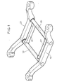
- the chassis comprises two main longitudinal beams 10 and 20 connected by crosspieces 30 and 40.
- the chassis further comprises two auxiliary beams 50 and 60, parallel to the auxiliary beams and connecting the two crosspieces. They are advantageously arranged each near one of the beams, which allows them to relieve the embedding of the sleepers in the main beams.
- the auxiliary beams give greater rigidity to the chassis and in particular to the cross members.
- the auxiliary beams can be made in the form of mechanically welded or molded tubes. They are welded to the crosspieces 30, 40.
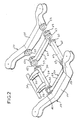
- the side members 10, 20 each consist of a beam 11, 21 and two connecting rings 12, 13; 22, 23, in this figure, only the rings 22, 23 of the spar 20 being clearly represented.
- the crosspieces 30, 40 each consist of a tube 31, 41 carrying two connecting rings 32, 33; 42, 43, and two brackets supporting a brake support bar 36, only the two brackets 34, 35 and the support bar 36 of the cross member 30 being shown.
- the auxiliary beams 50, 60 each consist of a beam 51, 61 and four connecting rings, only the connecting rings 62, 63, 64, 65 of the auxiliary beam 60 being clearly represented.
- connection between two adjacent crowns is carried out by bolting and, of course, in order to improve the position crowns between them, the connection may include a circular interlocking.
- the connection can also be achieved by bolts each passing through the four crowns, for example, the crowns 22, 64, 62, 33.
- Figure 3 shows an alternative embodiment in which the brake support bar is directly connected to the end of an auxiliary beam, so that the brackets are eliminated.
- the beam 61 of the secondary spar 60 is extended, beyond the connecting rings, by a protuberance 66 terminated by a connecting plate 66A.
- the bar 36 has a connecting plate 36A, and the two plates 36A, 66A are connected by bolting.
Abstract
Description
- La présente invention est relative à un châssis pour bogie de véhicule ferroviaire.
- Le châssis de bogie est la structure qui reçoit toutes les fonctions du bogie (support de caisse, support des roues, dispositifs de freinage, etc...) ; il sert à transmettre tous les efforts entre la caisse et les roues.
- Classiquement, un châssis de bogie comprend deux longerons parallèles reliés par deux traverses perpendiculaires aux longerons.
- Les efforts subis par le châssis sont importants à la jonction longeron-traverse.
- L'augmentation des vitesses d'exploitation des chemins de fer a pour conséquence d'augmenter les contraintes sur le châssis et, en particulier, les forces longitudinales exercées sur les longerons, notamment lors du freinage du véhicule.
- Le but de l'invention est de réaliser un châssis dans lequel l'encastrement de la traverse sur le longeron est soumis à des efforts moins importants lors des accélérations et décélérations.
- L'invention consiste donc à rajouter au moins un longeron auxiliaire, ce qui assure en outre une meilleure rigidité d'ensemble du châssis.
- L'invention a pour objet un châssis pour bogie de véhicule ferroviaire, comprenant deux longerons principaux reliés par deux traverses, caractérisé en ce qu'il comprend au moins un longeron auxiliaire reliant les deux traverses.
- De préférence, le châssis comprend deux longerons auxiliaires disposés chacun au voisinage d'un des longerons principaux et parallèlement à ceux-ci.
- Il est décrit ci-après, à titre d'exemple et en référence aux dessins annexés, deux modes de réalisation du châssis de bogie selon l'invention.
- La figure 1 représente une vue en perspective du premier mode de réalisation dans lequel les longerons auxiliaires sont soudés sur les traverses.
- La figure 2 représente une vue en perspective, partiellement éclatée, du deuxième mode de réalisation dans lequel chaque longeron auxiliaire est boulonné sur les traverses et sur un longeron principal.
- La figure 3 représente, en vue partielle, une variante du deuxième mode de réalisation.
- Dans la figure 1 le châssis comprend deux longerons longitudinaux principaux 10 et 20 reliés par des traverses 30 et 40.
- Conformément à l'invention, le châssis comprend en outre deux longerons auxilaires 50 et 60, parallèles aux longerons auxiliaires et reliant les deux traverses. Ils sont avantageusement disposés chacun à proximité d'un des longerons, ce qui leur permet de soulager les encastrements des traverses dans les longerons principaux.
- Les longerons auxiliaires confèrent une plus grande rigidité au châssis et notamment aux traverses.
- Les longerons auxiliaires peuvent être réalisés sous forme de tubes mécano-soudés ou moulés. Ils sont soudés sur les traverses 30, 40.
- On peut envisager de placer un seul longeron auxiliaire ou plus de deux et les fixer aux traverses selon un angle différent d'un angle droit.
- Dans la figure 2, les longerons 10, 20 se composent chacun d'une poutre 11, 21 et de deux couronnes de liaison 12, 13 ; 22, 23, dans cette figure, seules les couronnes 22, 23 du longeron 20 étant clairement représentées.
- Les traverses 30, 40 se composent chacune d'un tube 31, 41 portant deux couronnes de liaison 32, 33 ; 42, 43, et deux potences soutenant une barre-support de freins 36, seules les deux potences 34, 35 et la barre-support 36 de la traverse 30 étant représentées.
- Les longerons auxiliaires 50, 60 se composent chacun d'une poutre 51, 61 et de quatre couronnes de liaison, seules les couronnes de liaison 62, 63, 64, 65 du longeron auxiliaire 60 étant clairement représentées.
- La liaison mécanique entre deux couronnes adjacentes est réalisée par boulonnage et, bien entendu, afin d'améliorer le position nement des couronnes entre elles, la liaison peut comporter un emboîtement circulaire. La liaison peut aussi être réalisée par des boulons traversant chacun les quatre couronnes, par exemple, les couronnes 22, 64, 62, 33.
- La figure 3 montre une variante de réalisation dans laquelle la barre-support de freins est directement reliée à l'extrémité d'un longeron auxiliaire, de sorte que les potences sont supprimées.
- La poutre 61 du longeron secondaire 60 est prolongée, au-delà des couronnes de liaison, par une protubérance 66 terminée par une plaque de liaison 66A. La barre 36 comporte une plaque de liaison 36A, et les deux plaques 36A, 66A sont reliées par boulonnage.
Claims (5)
Applications Claiming Priority (4)
| Application Number | Priority Date | Filing Date | Title |
|---|---|---|---|
| FR8807621A FR2632594A1 (fr) | 1988-06-08 | 1988-06-08 | Chassis de bogie |
| FR8807621 | 1988-06-08 | ||
| FR8808137A FR2632918B1 (fr) | 1988-06-17 | 1988-06-17 | Chassis pour bogie de vehicule ferroviaire |
| FR8808137 | 1988-06-17 |
Publications (3)
| Publication Number | Publication Date |
|---|---|
| EP0345709A1 true EP0345709A1 (fr) | 1989-12-13 |
| EP0345709B1 EP0345709B1 (fr) | 1992-07-15 |
| EP0345709B2 EP0345709B2 (fr) | 1997-06-18 |
Family
ID=26226711
Family Applications (1)
| Application Number | Title | Priority Date | Filing Date |
|---|---|---|---|
| EP19890110160 Expired - Lifetime EP0345709B2 (fr) | 1988-06-08 | 1989-06-05 | Châssis pour bogie de véhicule ferroviaire |
Country Status (4)
| Country | Link |
|---|---|
| EP (1) | EP0345709B2 (fr) |
| CA (1) | CA1329055C (fr) |
| DE (1) | DE68902101T3 (fr) |
| ES (1) | ES2034505T5 (fr) |
Cited By (8)
| Publication number | Priority date | Publication date | Assignee | Title |
|---|---|---|---|---|
| EP0441313A2 (fr) * | 1990-02-05 | 1991-08-14 | Fuji Jukogyo Kabushiki Kaisha | Chassis de bogie pour véhicule ferroviaire |
| DE4326709A1 (de) * | 1993-08-09 | 1995-02-16 | Rother Klemens Dipl Ing Fh | Rahmenstruktur für Schwebegestelle |
| FR2720362A1 (fr) * | 1994-05-30 | 1995-12-01 | Gec Alsthom Transport Sa | Chassis de bogie. |
| WO2001030629A1 (fr) * | 1999-10-27 | 2001-05-03 | Techni Industrie | Boggie de type evolutif notamment pour wagons de transport de marchandises |
| CN102886634A (zh) * | 2012-10-17 | 2013-01-23 | 南车株洲电力机车有限公司 | 一种适用于转向架圆形部件间焊接的连接座 |
| CN103661475A (zh) * | 2013-12-13 | 2014-03-26 | 齐齐哈尔轨道交通装备有限责任公司 | 一种铁路货车转向架及其构架 |
| WO2016131691A1 (fr) * | 2015-02-17 | 2016-08-25 | Siemens Ag Österreich | Poutre de liaison pour deux longerons d'un véhicule ferroviaire |
| CN106740963A (zh) * | 2017-01-23 | 2017-05-31 | 中车长江车辆有限公司 | 铁路快运货车转向架用构架 |
Families Citing this family (1)
| Publication number | Priority date | Publication date | Assignee | Title |
|---|---|---|---|---|
| CN107470822B (zh) * | 2017-07-28 | 2019-05-14 | 中车南京浦镇车辆有限公司 | 环形焊接垫板的安装方法 |
Citations (3)
| Publication number | Priority date | Publication date | Assignee | Title |
|---|---|---|---|---|
| FR1452450A (fr) * | 1965-10-29 | 1966-02-25 | Henricot Usines Emile Sa | Bogie à trois essieux |
| DE1455189A1 (de) * | 1962-08-31 | 1969-02-06 | Sambre & Meuse Usines | Wiegenloses Drehgestell fuer Eisenbahnfahrzeuge |
| DE1455175A1 (de) * | 1962-03-16 | 1969-02-20 | Usines Emile Henricot Sa Des | Drehgestell aus Gussstahl fuer Waggons sowie kennzeichnende Teile dieses Drehgestells |
-
1989
- 1989-06-05 EP EP19890110160 patent/EP0345709B2/fr not_active Expired - Lifetime
- 1989-06-05 DE DE68902101T patent/DE68902101T3/de not_active Expired - Fee Related
- 1989-06-05 ES ES89110160T patent/ES2034505T5/es not_active Expired - Lifetime
- 1989-06-07 CA CA 601970 patent/CA1329055C/fr not_active Expired - Fee Related
Patent Citations (3)
| Publication number | Priority date | Publication date | Assignee | Title |
|---|---|---|---|---|
| DE1455175A1 (de) * | 1962-03-16 | 1969-02-20 | Usines Emile Henricot Sa Des | Drehgestell aus Gussstahl fuer Waggons sowie kennzeichnende Teile dieses Drehgestells |
| DE1455189A1 (de) * | 1962-08-31 | 1969-02-06 | Sambre & Meuse Usines | Wiegenloses Drehgestell fuer Eisenbahnfahrzeuge |
| FR1452450A (fr) * | 1965-10-29 | 1966-02-25 | Henricot Usines Emile Sa | Bogie à trois essieux |
Cited By (18)
| Publication number | Priority date | Publication date | Assignee | Title |
|---|---|---|---|---|
| EP0441313A2 (fr) * | 1990-02-05 | 1991-08-14 | Fuji Jukogyo Kabushiki Kaisha | Chassis de bogie pour véhicule ferroviaire |
| EP0441313A3 (en) * | 1990-02-05 | 1991-11-27 | Fuji Jukogyo Kabushiki Kaisha | Bogie frame for railway vehicle |
| US5085151A (en) * | 1990-02-05 | 1992-02-04 | Fuji Jukogyo Kabushiki Kaisha | Bogie frame for railway vehicle and method thereof |
| DE4326709A1 (de) * | 1993-08-09 | 1995-02-16 | Rother Klemens Dipl Ing Fh | Rahmenstruktur für Schwebegestelle |
| FR2720362A1 (fr) * | 1994-05-30 | 1995-12-01 | Gec Alsthom Transport Sa | Chassis de bogie. |
| EP0685377A1 (fr) * | 1994-05-30 | 1995-12-06 | Gec Alsthom Transport Sa | Chassis de bogie |
| US5653177A (en) * | 1994-05-30 | 1997-08-05 | Gec Alsthom Transport Sa | Bogie frame |
| FR2800342A1 (fr) * | 1999-10-27 | 2001-05-04 | Techni Ind | Boggie de type evolutif notamment pour wagons de transport de marchandises |
| WO2001030629A1 (fr) * | 1999-10-27 | 2001-05-03 | Techni Industrie | Boggie de type evolutif notamment pour wagons de transport de marchandises |
| CN102886634A (zh) * | 2012-10-17 | 2013-01-23 | 南车株洲电力机车有限公司 | 一种适用于转向架圆形部件间焊接的连接座 |
| CN103661475A (zh) * | 2013-12-13 | 2014-03-26 | 齐齐哈尔轨道交通装备有限责任公司 | 一种铁路货车转向架及其构架 |
| WO2016131691A1 (fr) * | 2015-02-17 | 2016-08-25 | Siemens Ag Österreich | Poutre de liaison pour deux longerons d'un véhicule ferroviaire |
| CN107207019A (zh) * | 2015-02-17 | 2017-09-26 | 奥地利西门子公司 | 用于轨道车辆的两个纵向构件的连接构件 |
| US20180043909A1 (en) * | 2015-02-17 | 2018-02-15 | Seimens Ag Österreich | Connecting Member for Two Longitudinal Members of a Rail Vehicle |
| RU2675757C1 (ru) * | 2015-02-17 | 2018-12-24 | Сименс Аг Эстеррайх | Соединительная балка для двух лонжеронов рельсового транспортного средства |
| CN107207019B (zh) * | 2015-02-17 | 2019-07-16 | 西门子移动有限责任公司 | 用于轨道车辆的两个纵向构件的连接构件 |
| US10745035B2 (en) | 2015-02-17 | 2020-08-18 | Siemens Mobility Austria Gmbh | Connecting member for two longitudinal members of a rail vehicle |
| CN106740963A (zh) * | 2017-01-23 | 2017-05-31 | 中车长江车辆有限公司 | 铁路快运货车转向架用构架 |
Also Published As
| Publication number | Publication date |
|---|---|
| DE68902101T2 (de) | 1993-02-04 |
| DE68902101T3 (de) | 1997-08-21 |
| EP0345709B1 (fr) | 1992-07-15 |
| DE68902101D1 (de) | 1992-08-20 |
| CA1329055C (fr) | 1994-05-03 |
| EP0345709B2 (fr) | 1997-06-18 |
| ES2034505T3 (es) | 1993-04-01 |
| ES2034505T5 (es) | 1997-08-01 |
Similar Documents
| Publication | Publication Date | Title |
|---|---|---|
| EP0345709B1 (fr) | Châssis pour bogie de véhicule ferroviaire | |
| EP0653344B1 (fr) | Châssis pour véhicule automobile | |
| IT1237633B (it) | Freno a disco per ruote di autoveicoli anti-inquinante. | |
| DE68907253T2 (de) | Radaufhaengung. | |
| DE3874515D1 (de) | Vorderachse. | |
| EP0326368A3 (fr) | Appareil de déminage | |
| CA2476844A1 (fr) | Suspension independante pour vehicule polyvalent | |
| EP0039641B1 (fr) | Frein à action ponctuelle | |
| FR2460824A1 (fr) | Vehicule ferroviaire | |
| ATE97333T1 (de) | Schienengefuehrtes fahrzeug fuer hochbahnen. | |
| FR2632918A1 (fr) | Chassis pour bogie de vehicule ferroviaire | |
| FR2759659A1 (fr) | Vehicule ferroviaire a tete susceptible de se deformer de maniere controlee, lorsqu'elle est sujette a des sollicitations par choc importantes | |
| CA1331719C (fr) | Chassis de bogie | |
| SE9902063L (sv) | Anordning för ett dragfordon | |
| ITTO920200A1 (it) | Meccanismo di sterzatura delle ruote posteriori per autovetture a quattro ruote sterzanti dotate di ponte ad omega della sospensione posteriore. | |
| EP0630799B1 (fr) | Train de roulement pour véhicule circulant sur une voie de guidage | |
| IT1219195B (it) | Dispositivo meccanico di sterzatura delle ruote posteriori per autovetture a quattro ruote sterzanti | |
| FR2645800A1 (fr) | Train de roues notamment du type mac-pherson a traverse inferieure de filtrage | |
| FI76970B (fi) | Larvelement foer fordon. | |
| FR2403222A1 (fr) | Systeme de suspension a poutres articulees pour un vehicule a roues, et vehicule correspondant | |
| CA2322414A1 (fr) | Dispositif pour transmettre les forces longitudinales d'un bati tournant sur la caisse d'un vehicule sur rails, notamment d'un vehicule moteur a force de traction elevee | |
| EP0318922A1 (fr) | Suspension primaire pour véhicules ferroviaires | |
| FR2713728A1 (fr) | Dispositif de serrage rapide d'éléments mobiles dans un habitacle de véhicules. | |
| EP1052154A1 (fr) | Caisse équipée de véhicule notamment ferroviaire | |
| KR100469956B1 (ko) | 셀프로다의 후부발판장치 |
Legal Events
| Date | Code | Title | Description |
|---|---|---|---|
| PUAI | Public reference made under article 153(3) epc to a published international application that has entered the european phase |
Free format text: ORIGINAL CODE: 0009012 |
|
| AK | Designated contracting states |
Kind code of ref document: A1 Designated state(s): DE ES FR GB IT SE |
|
| 17P | Request for examination filed |
Effective date: 19900611 |
|
| RAP1 | Party data changed (applicant data changed or rights of an application transferred) |
Owner name: GEC ALSTHOM SA |
|
| 17Q | First examination report despatched |
Effective date: 19910527 |
|
| GRAA | (expected) grant |
Free format text: ORIGINAL CODE: 0009210 |
|
| AK | Designated contracting states |
Kind code of ref document: B1 Designated state(s): DE ES FR GB IT SE |
|
| PG25 | Lapsed in a contracting state [announced via postgrant information from national office to epo] |
Ref country code: GB Effective date: 19920715 |
|
| REF | Corresponds to: |
Ref document number: 68902101 Country of ref document: DE Date of ref document: 19920820 |
|
| GBT | Gb: translation of ep patent filed (gb section 77(6)(a)/1977) | ||
| ITF | It: translation for a ep patent filed |
Owner name: JACOBACCI & PERANI S.P.A. |
|
| REG | Reference to a national code |
Ref country code: ES Ref legal event code: FG2A Ref document number: 2034505 Country of ref document: ES Kind code of ref document: T3 |
|
| PLBI | Opposition filed |
Free format text: ORIGINAL CODE: 0009260 |
|
| 26 | Opposition filed |
Opponent name: DUEWAG AKTIENGESELLSCHAFT Effective date: 19930413 |
|
| EAL | Se: european patent in force in sweden |
Ref document number: 89110160.2 |
|
| PLAW | Interlocutory decision in opposition |
Free format text: ORIGINAL CODE: EPIDOS IDOP |
|
| PLAW | Interlocutory decision in opposition |
Free format text: ORIGINAL CODE: EPIDOS IDOP |
|
| PUAH | Patent maintained in amended form |
Free format text: ORIGINAL CODE: 0009272 |
|
| STAA | Information on the status of an ep patent application or granted ep patent |
Free format text: STATUS: PATENT MAINTAINED AS AMENDED |
|
| PGFP | Annual fee paid to national office [announced via postgrant information from national office to epo] |
Ref country code: GB Payment date: 19970513 Year of fee payment: 9 |
|
| 27A | Patent maintained in amended form |
Effective date: 19970618 |
|
| AK | Designated contracting states |
Kind code of ref document: B2 Designated state(s): DE ES FR GB IT SE |
|
| REG | Reference to a national code |
Ref country code: ES Ref legal event code: DC2A Kind code of ref document: T5 Effective date: 19970624 |
|
| ITF | It: translation for a ep patent filed |
Owner name: JACOBACCI & PERANI S.P.A. |
|
| GBV | Gb: ep patent (uk) treated as always having been void in accordance with gb section 77(7)/1977 [no translation filed] |
Effective date: 19920715 |
|
| PGFP | Annual fee paid to national office [announced via postgrant information from national office to epo] |
Ref country code: SE Payment date: 20070614 Year of fee payment: 19 |
|
| PGFP | Annual fee paid to national office [announced via postgrant information from national office to epo] |
Ref country code: DE Payment date: 20070622 Year of fee payment: 19 |
|
| PGFP | Annual fee paid to national office [announced via postgrant information from national office to epo] |
Ref country code: ES Payment date: 20070628 Year of fee payment: 19 |
|
| PGFP | Annual fee paid to national office [announced via postgrant information from national office to epo] |
Ref country code: IT Payment date: 20070626 Year of fee payment: 19 |
|
| PGFP | Annual fee paid to national office [announced via postgrant information from national office to epo] |
Ref country code: FR Payment date: 20070615 Year of fee payment: 19 |
|
| EUG | Se: european patent has lapsed | ||
| REG | Reference to a national code |
Ref country code: FR Ref legal event code: ST Effective date: 20090228 |
|
| PG25 | Lapsed in a contracting state [announced via postgrant information from national office to epo] |
Ref country code: DE Free format text: LAPSE BECAUSE OF NON-PAYMENT OF DUE FEES Effective date: 20090101 |
|
| REG | Reference to a national code |
Ref country code: ES Ref legal event code: FD2A Effective date: 20080606 |
|
| PG25 | Lapsed in a contracting state [announced via postgrant information from national office to epo] |
Ref country code: FR Free format text: LAPSE BECAUSE OF NON-PAYMENT OF DUE FEES Effective date: 20080630 Ref country code: IT Free format text: LAPSE BECAUSE OF NON-PAYMENT OF DUE FEES Effective date: 20080605 |
|
| PG25 | Lapsed in a contracting state [announced via postgrant information from national office to epo] |
Ref country code: ES Free format text: LAPSE BECAUSE OF NON-PAYMENT OF DUE FEES Effective date: 20080606 |
|
| PG25 | Lapsed in a contracting state [announced via postgrant information from national office to epo] |
Ref country code: SE Free format text: LAPSE BECAUSE OF NON-PAYMENT OF DUE FEES Effective date: 20080606 |