EP0345020B1 - Vorrichtung zum Trocknen und Kristallisieren von Granulat - Google Patents
Vorrichtung zum Trocknen und Kristallisieren von Granulat Download PDFInfo
- Publication number
- EP0345020B1 EP0345020B1 EP89305440A EP89305440A EP0345020B1 EP 0345020 B1 EP0345020 B1 EP 0345020B1 EP 89305440 A EP89305440 A EP 89305440A EP 89305440 A EP89305440 A EP 89305440A EP 0345020 B1 EP0345020 B1 EP 0345020B1
- Authority
- EP
- European Patent Office
- Prior art keywords
- granules
- heating tank
- drying
- tank
- material outlet
- Prior art date
- Legal status (The legal status is an assumption and is not a legal conclusion. Google has not performed a legal analysis and makes no representation as to the accuracy of the status listed.)
- Expired - Lifetime
Links
Images


Classifications
-
- F—MECHANICAL ENGINEERING; LIGHTING; HEATING; WEAPONS; BLASTING
- F26—DRYING
- F26B—DRYING SOLID MATERIALS OR OBJECTS BY REMOVING LIQUID THEREFROM
- F26B3/00—Drying solid materials or objects by processes involving the application of heat
- F26B3/32—Drying solid materials or objects by processes involving the application of heat by development of heat within the materials or objects to be dried, e.g. by fermentation or other microbiological action
- F26B3/34—Drying solid materials or objects by processes involving the application of heat by development of heat within the materials or objects to be dried, e.g. by fermentation or other microbiological action by using electrical effects
- F26B3/343—Drying solid materials or objects by processes involving the application of heat by development of heat within the materials or objects to be dried, e.g. by fermentation or other microbiological action by using electrical effects in combination with convection
-
- B—PERFORMING OPERATIONS; TRANSPORTING
- B29—WORKING OF PLASTICS; WORKING OF SUBSTANCES IN A PLASTIC STATE IN GENERAL
- B29B—PREPARATION OR PRETREATMENT OF THE MATERIAL TO BE SHAPED; MAKING GRANULES OR PREFORMS; RECOVERY OF PLASTICS OR OTHER CONSTITUENTS OF WASTE MATERIAL CONTAINING PLASTICS
- B29B13/00—Conditioning or physical treatment of the material to be shaped
- B29B13/06—Conditioning or physical treatment of the material to be shaped by drying
- B29B13/065—Conditioning or physical treatment of the material to be shaped by drying of powder or pellets
-
- B—PERFORMING OPERATIONS; TRANSPORTING
- B29—WORKING OF PLASTICS; WORKING OF SUBSTANCES IN A PLASTIC STATE IN GENERAL
- B29B—PREPARATION OR PRETREATMENT OF THE MATERIAL TO BE SHAPED; MAKING GRANULES OR PREFORMS; RECOVERY OF PLASTICS OR OTHER CONSTITUENTS OF WASTE MATERIAL CONTAINING PLASTICS
- B29B9/00—Making granules
- B29B9/16—Auxiliary treatment of granules
-
- F—MECHANICAL ENGINEERING; LIGHTING; HEATING; WEAPONS; BLASTING
- F26—DRYING
- F26B—DRYING SOLID MATERIALS OR OBJECTS BY REMOVING LIQUID THEREFROM
- F26B17/00—Machines or apparatus for drying materials in loose, plastic, or fluidised form, e.g. granules, staple fibres, with progressive movement
- F26B17/18—Machines or apparatus for drying materials in loose, plastic, or fluidised form, e.g. granules, staple fibres, with progressive movement with movement performed by rotating helical blades or other rotary conveyors which may be heated moving materials in stationary chambers, e.g. troughs
- F26B17/20—Machines or apparatus for drying materials in loose, plastic, or fluidised form, e.g. granules, staple fibres, with progressive movement with movement performed by rotating helical blades or other rotary conveyors which may be heated moving materials in stationary chambers, e.g. troughs the axis of rotation being horizontal or slightly inclined
-
- B—PERFORMING OPERATIONS; TRANSPORTING
- B29—WORKING OF PLASTICS; WORKING OF SUBSTANCES IN A PLASTIC STATE IN GENERAL
- B29B—PREPARATION OR PRETREATMENT OF THE MATERIAL TO BE SHAPED; MAKING GRANULES OR PREFORMS; RECOVERY OF PLASTICS OR OTHER CONSTITUENTS OF WASTE MATERIAL CONTAINING PLASTICS
- B29B9/00—Making granules
- B29B9/16—Auxiliary treatment of granules
- B29B2009/165—Crystallizing granules
Definitions
- the present invention relates to a drying and crystallizing apparatus for granules, and more particularly to a drying and crystallizing apparatus for granules which are formed mainly of synthetic resin.
- granules of synthetic resin are dried, or those of petrochemical resin of crystalline synthetic resin are crystallized, in such a manner that usually a sealed processing tank is used and the granules charged therein are supplied with hot air from below.
- the granules when a temperature of material becomes higher than a predetermined degree , the granules are softened and mutually fused to make difficult uniform hot-air-drying, or are oxidized at the surface, whereby they are not usable as molding material. Hence, the granules must be dried by hot air at a lower temperature than the predetermined degree , thereby creating the problem in that the time is required to that extent for drying them.
- the applicant directs his attention to that the granules including water content are heated from the interior by microwaves, so that such heating is convenient for dispersing the water content in the granules onto the surfaces thereof. He has proposed a granule drying and crystallizing apparatus which can dry or crystallize the granules in a short time by using the microwaves and made an application for a patent ( Patent Application No. Sho 62-314920 ).
- Such internal heating is very efficient, but has a problem in that variation is caused in the heating of granules in the processing tank.
- the problem is soluble at one side in such a manner that the granules are agitated by rotation of vanes provided in the processing tank.
- the use of such usual agitating vanes makes not-uniform a residence time of granules in the processing tank, in other words, the time of microwave-heating the granules while staying the same, thereby creating a problem in that variation in the heating still remains.
- the heating by the microwaves is efficient to quickly reach the temperature of drying the granules, whereby they are heated earlier than dried by vaporizing the water content.
- the radiation of microwaves must often be interrupted not to fuse them due to an excessive high temperature during the drying. According , the problem also is created in that an expensive microwave apparatus is obliged to be idle without a full operation, which is very uneconomical.
- GB-A-2 110 803 discloses drying apparatus which comprises a screw-conveyor which extends axially through a shell to progress material from an inlet to a discharge portion through several treatment sections, one of which is a microwave drying section. Upstream of the microwave drying section is a steam/hot water heating section which removes the bulk of the residual moisture from the material. Downstream of the microwave drying section is a material cooling section.
- FR-A-2 224 268 discloses treatment apparatus which comprises a heating vessel and a drying vessel.
- the cylindrical heating vessel is enclosed in a steam-heated envelope and material is moved through the vessel by a number of shaft-mounted blades.
- Each blade comprises an arm having a plate at its free end, the plates being angled to push the material through the vessel as the shaft rotates.
- the drying vessel is provided with a through flow of heated air.
- a main object of the invention is to provide a drying and crystallizing apparatus for granules, which eliminates non-uniform heating caused by irregular reflection of microwaves and variation in the residence time of granules in the processing tank so that the granules mainly of synthetic resin can be heated by the microwaves, thereby performing continuously uniform drying or crystallization.
- Another object of the invention is to provide an inexpensive drying apparatus for granules, which can improve operating rates and reduce drying time.
- One aspect of the present invention relates to drying and crystallizing apparatus for granules, which is provided with a heating tank formed in a rectangular parallelepiped and having at one lengthwise side a material inlet and at the other lengthwise side a material outlet and with a microwave unit for radiating microwaves onto the granules charged in the heating tank, a plurality of disc-like partitions across the material inlet and material outlet of the heating tank to form a plurality of partitioned spaces between the respective adjacent partitions, and agitating vanes which agitate the granules in the partitioned spaces between the respective partitions and transfer them to the adjacent space at the material outlet side.
- a driving shaft disposed in the heating tank rotates to allow the vanes to agitate the granules within the spaces between the partitions, so that even when the microwaves radiated from microwave units are irregularly reflected in the heating tank, no variation is caused in heating the granules, and since the granules in each space are sequentially transferred by rotation of the agitating vanes toward the adjacent space at the material outlet side, variation in the residence time of the granules subjected to the microwave heating in the heating tank is eliminated. Accordingly, the microwaves radiate onto the granules of synthetic resin continuously charged in the heating tank, thereby enabling the entire granules to be uniformly and continuously dried and crystallized.
- Another aspect of the present invention is further characterized in that separately from a sealed heating tank having a material inlet and outlet and provided with a microwave unit, a sealed drying tank is provided which has a material inlet and a material outlet and is provided with a diffusor for dehumidifying air from a dehumidifying air feeder, and between the material output of the heating tank and the material inlet of the drying tank is provided connecting means for connecting the heating tank and drying tank, so that the granules heated by the heating tank are dried in the drying tank.
- the granules charged in the heating tank through the material inlet are quickly heated up to an optinmum temperature to dry them by radiating the microwaves, the heated granules being discharged from the material outlet without waiting for drying, charged into the separate drying tank through the connecting means, and dried in the drying tank by the dehumidifying air from the dehumidifying air feeder.
- the drying capacity of the drying tank corresponds to the heating capacity of the heating tank, so that the microwave unit can always demonstrate its capacity without interrupting the microwave radiation, thereby improving its operating rate and enabling the granules to be continuously dried.
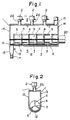
- a first embodiment of a drying and crystallizing apparatus for granules of the invention which heats, dries and crystallizes granules by a heating tank 1.
- the heating tank 1 comprises a top wall 11, a bottom wall 12, both side walls 13, and both end walls 14, and is formed in a rectangular parallelepiped and sealed.
- a plurality of microwave units 2 provided with waveguides 2a are disposed in series on the top wall 11 so that microwaves can be radiated from the waveguides 2a into the heating tank 1.
- a material inlet 15 is provided at one lengthwise end of the top wall 11.
- the bottom wall 12 is downwardly semicircularly curved , so that the heating tank 1 is U-like-shaped in section with the bottom wall 12 and both the side walls 13.
- a material outlet 16 is provided at one lengthwise end of the bottom wall 12 reverse to the material inlet 15, a discharge pipe 18 provided with a rotary feeder 17 continuously discharging therethrough the granules is provided at the material outlet 16, and at the upper portion of the discharge pipe 18 and above the rotary feeder 17 is mounted a dehumidifying air feed pipe 19.
- a driving shaft 3 is disposed at the center of the semicircularly bent bottom wall 12.
- the driving shaft 3 carries a plurality of disc-like partitions 4 for forming the plurality of partitioned spaces S therebewteen and across the material inlet 15 and material outlet 16, is supported rotatably to the heating tank 1, perforates the heating tank 1 lengthwise and at the lower portion thereof, projects at one end at the material inlet 15 side outwardly of the end wall 14, and rotatably connects to a driving unit 20 of a motor or the like.
- the partitions 4 are mounted on the driving shaft 3 in relation of being spaced lengthwise thereof and at regular intervals and each provided with agitating vanes 5 for agitating the granules in each partitioned space S and conveying them to the adjacent partitioned space S at the material outlet 16 side. Also, the partitions 4 each have an outer diameter slightly smaller than an inner diameter of the semicircularly bent bottom wall 12, are disposed concentrically therewith , and form the partitioned spaces S between the respective adjacent partitions 4.
- the agitating vanes 5, as shown in Fig. 3, are plate-like-shaped, provided at the outer periphery of each disc-like partition 4, spaced at a phase difference of 120°, and extend in parallel to the driving shaft 3 and toward the material inlet 15.
- the granules charged in the heating tank 1, while being agitated by the rotating vanes 5, are transferred to the adjacent partitioned space S .
- the granules are continuously charged into the heating tank 1 through the material inlet 15 and controlled to correspond to the transfer capacity of each partition 5 to an extent of covering the driving shaft 3 in each partitioned space S .
- the granules thus agitated and transferred to each partitioned space S are radiated by the microwaves from the microwave units 2 and heated thereby.
- Water content included in the granules is vapored by heating and exhausted,together with the dehumidifying air fed from the dehumidifying air supply pipe 19,outwardly of the heating tank 1 through the material inlet 15, thereby drying or crystallizing the granules.
- the rotary feeder 17 is driven to discharge the dried or crystallized granules outwardly through the material outlet 16.
- the granules charged in the heating tank 1 are stepwise transferred to each partitioned space and uniformly agitated therein and then discharged, thereby enabling the variation in heating to be eliminated. Moreover, the granules agitated and sequentially transferred to the adjacent partitioned space S are reduced in variation in the residence time when they stay in the heating tank 1 so as to be heated by the microwaves.
- each disc-like partition 4 is 150 mm in diameter D and spaced apart at an interval of 100 mm
- each agitating vane 5 is 70 mm in length l 1 and 300 mm in width L 2, so that when granules of petrochemical resin of 3 to 5 mm in grain diameter are transferred at a speed of 60 kg per hour and the residence time of granules aims at 20 minutes, the frequency distribution of the residence time of granules at the material outlet 16 has been measured, thereby obtaining the result as shown in Fig. 4.
- the frequency distribution of the residence time is obtained in such a manner that, while keeping an amount of granules in each partitioned space S to an extent of covering the driving shaft 3, colored granules discriminated from those to be dried are charged into the heating tank 1 at a predetermined amount every predetermined time to thereby count the number of the colored granules included in the granules discharged from the material outlet 16.
- the agitating vanes 5 may be provided at both sides of each partition 4. Furthermore, as shown in Fig.5, the agitating vanes 5 may connect the respective adjacent partitions 4, in which frameworks are formed to improve strength as a whole.
- agitating vanes 5 are not limited in number and configuration to those in the first embodiment.
- a drying tank may be provided independently of the heating tank 1, so that dehumidifying air is supplied to the drying tank for drying the granules.
- the material inlet 22 connects with a material storage tank 27 through a valve 28.
- a return pipe 31 of a dehumidifying air supply unit 30 to be discussed below is mounted on the upper portion of one side wall of the heating tank 21 at the material inlet 22 side.
- An opening 34 is provided at the lower wall of heating tank 21 in the vicinity of the material outlet 23,and a punching plate 35 having a large number of orifices through which the granules cannot pass is mounted at the opening 34. Furthermore, a rotary shaft 38, on which a large number of disc-like partitions 36 provided with agitating vanes 37 are mounted , perforates the heating tank 21 and is adapted to rotate by a driving unit 39, such as a motor or the like.
- a drying tank 40 funnel-shaped at the lower portion and sealed is provided below the heating tank 21, a material inlet 41 is provided at the upper wall of the drying tank 40, a material outlet 42 is provided at the lower end thereof, and a discharge pipe 44 provided with a rotary feeder 43 connects with the material outlet 42. Furthermore, a conical diffuser 45 for dehumidifying air is provided at the inside lower portion of the drying tank 40 and connects with the dehumidifying air supply unit 30 through a blast pipe 46.
- the dehumidifying air supply unit 30 is provided with a heater (not shown ) or the like so as to adjust the temperature of dehumidifying air blown-off into the drying tank 40.
- the material outlet 23 at the heating tank 21 connects with the material inlet 41 at the drying tank 40 through a connecting pipe 48 having a rotary feeder 47.
- an air connecting pipe 49 is provided between the upper wall of the drying tank 40 and the opening 34 at the bottom wall of the heating tank 21, so that the dehumidifying air blown-off into the drying tank 40 returns to the dehumidifying air supply unit 30 through the air connecting pipe 49, heating tank 21, and return pipe 31.
- the second embodiment of the drying apparatus constructed as the above-mentioned dries the granules in such a manner that the rotary shaft 38 is driven by the driving unit 39 to rotate the agitating vanes 37 together with the disc-like partitions 36 so that the granules are heated by the microwaves while reducing variation in the residence time, and then discharged from the heating tank 21 by the rotary feeder 47 through the material outlet 23.
- the granules in the storage tank 27 are continuously charged into the tank 21 through the material inlet 22 to the extent that the granules are charged slightly higher than the level of rotary shaft 38 in each partitioned space S between the respective pertitions 36.
- the microwaves from the microwave unit 24 are radiated on the granules in the heating tank 21 through the wave guide 25 to heat them up to the most suitable high temperature required for drying them with the dehumidifying air in the drying tank 40.
- the heated granules are sequentially discharged by the rotary feeder 47 to the connecting pipe 48 through the material outlet 23 and sequentially charged into the drying tank 40 through the material inlet 41 thereof, so that the granules are dried by the dehumidifying air which is sent from the dehumidifying air supply unit 30 and blown off through the diffuser 45, at which time the granules are dried while adjusting at need the temperature of dehumidifying air.
- the temperature of dehumidifying air may be raised or lowered.
- the dried granules are sequentially discharged from the drying tank 40 by the rotary feeder 43 through the material outlet 42.
- the granules in the heating tank 21 are quickly heated by radiation of the microwaves up to the optimum temperature and then charged in the separate drying tank 40 to be dried therein by the dehumidifying air.
- the drying capacity of drying tank 40 corresponds to the heating capacity of heating tank 21, thereby enabling the microwave unit 24 to be operated without interrupting the microwave radiation,and its operating rate to be improved.
- the return pipe 31 connected to the heating tank 21 in this embodiment may be open in the atomosphere.
- the air connecting pipe 49 may alternatively be omitted so as to separately supply the humidifying air to the heating tank 21 and drying tank 40.
Landscapes
- Engineering & Computer Science (AREA)
- Mechanical Engineering (AREA)
- Life Sciences & Earth Sciences (AREA)
- Microbiology (AREA)
- General Engineering & Computer Science (AREA)
- Health & Medical Sciences (AREA)
- Biomedical Technology (AREA)
- Biotechnology (AREA)
- Molecular Biology (AREA)
- Drying Of Solid Materials (AREA)
- Processing And Handling Of Plastics And Other Materials For Molding In General (AREA)
Claims (7)
- Trocknungs- und Kristallisiervorrichtung für Granulatkörner mit:(a) einem länglichen Erwärmungstank (1; 21), welcher an einer seiner Längsseiten einen Materialeinlaß (15; 22) und an der anderen Längsseite einen Materialauslaß (16; 23) aufweist, und(b) Mikrowelleneinheiten (2; 24) zur Ausstrahlung von Mikrowellen auf die durch den Materialeinlaß (15; 22) in den Erwärmungstank (1; 21) eingefüllten Granulatkörner, dadurch gekennzeichnet, daß:(c) eine in den Erwärmungstank eingebaute Rühreinheit zum Rühren der Granulatkörner folgendes umfaßt:(c-1) eine Antriebswelle (3; 38), welche horizontal an dem unteren Teil des Erwärmungstanks angeordnet ist;(c-2) eine Mehrzahl von durch die Antriebswelle (3; 38) gelagerte und gedrehte scheibenartige Abtrennungen (4; 36), wobei die Abtrennungen senkrecht zur Achse der Antriebswelle stehen und voneinander beabstandet sind, um in dem Erwärmungstank (1; 21) eine Mehrzahl von abgetrennten Räumen über den Materialeinlaß (15; 22) und den Materialauslaß (16; 23) zur Verfügung zu stellen; und(c-3) an jeder der Abtrennungen angebrachte Rührflügel (5; 37) zum Rühren der Granulatkörner in Drehrichtung in jedem der abgetrennten Räume, wodurch die in den Erwärmungstank (1; 21) eingefüllten Granulatkörner in Drehrichtung der Rührflügel (5; 37) in jedem der beabstandeten Räume aufgenommen und gerührt werden, und wodurch bei Entstehung eines Höhenunterschiedes zwischen einer Ebene von Granulatkörnern in einem abgetrennten Raum an der Materialeinlaßseite und einer Ebene von Granulatkörnern in einem benachbarten abgetrennten Raum an der Materialauslaßseite, wobei die Granulatkörner in den Erwärmungstank (1;21) eingebracht und/oder aus diesem ausgegeben werden, der Höhenunterschied ein Übergehen der in dem abgetrennten Raum an der Materialeinlaßseite gerührten Granulatkörner in den benachbarten abgetrennten Raum an der Materialauslaßseite bewirkt, und dadurch werden die in den Erwärmungstank (1; 21) eingefüllten Granulatkörner zum Materialauslaß (16; 23) transportiert, während sie in jedem der abgetrennten Räume gerührt werden.
- Trocknungs- und Kristallisiervorrichtung für Granulatkörner gemäß Anspruch 1, bei der der Erwärmungstank (1) mit einer im Querschnitt halbkreisförmigen Bodenwandung (12) versehen ist, jede der scheibenförmigen Abtrennungen (4) einen Durchmesser aufweist, welcher kleiner als ein Innendurchmesser der Bodenwandung (12) ist, die Antriebswelle (3) an der Achse der Bodenwandung (12) angeordnet ist und die Abtrennungen (4) mit der Bodenwandung (12) konzentrisch angeordnet sind.
- Trocknungs- und Kristallisiervorrichtung für Granulatkörner gemäß Anspruch 1, bei der der Erwärmungstank (1) an der Materialauslaßseite mit einem Rohr (19) zur Zufuhr von Entfeuchtungsluft versehen ist.
- Trocknungs- und Kristallisiervorrichtung für Granulatkörner mit(a) einem länglichen Erwärmungstank (21), welcher an einer seiner Längsseiten einen Materialeinlaß (22) und an der anderen Längsseite einen Materialauslaß (23) aufweist, und(b) Mikrowelleneinheiten (24) zur Ausstrahlung von Mikrowellen auf die durch den Materialeinlaß (22) in den Erwärmungstank (21) eingefüllten Granulatkörner, dadurch gekennzeichnet, daß:(c) eine in den Erwärmungstank eingebaute Rühreinheit zum Rühren der Granulatkörner (41) folgendes umfaßt:(c-1) eine Antriebswelle (38), welche horizontal an dem unteren Teil des Erwärmungstanks angeordnet ist;(c-2) eine Mehrzahl von durch die Antriebswelle (38) gelagerte und gedrehte scheibenartige Abtrennungen (36), wobei die Abtrennungen senkrecht zur Achse der Antriebswelle stehen und voneinander beabstandet sind, um in dem Erwärmungstank (21) eine Mehrzahl von abgetrennten Räumen über den Materialeinlaß (22) und den Materialauslaß (23) zur Verfügung zu stellen;(c-3) an jeder der Abtrennungen angebrachte Rührflügel (37) zum Rühren der Granulatkörner in Drehrichtung in jedem der abgetrennten Räume, wodurch die in den Erwärmungstank (21) eingefüllten Granulatkörner in Drehrichtung der Rührflügel (37) in jedem der beabstandeten Räume aufgenommen und gerührt werden, und wodurch bei Entstehung eines Höhenunterschiedes zwischen einer Ebene von Granulatkörnern in einem abgetrennten Raum an der Materialeinlaßseite und einer Ebene von Granulatkörnern in einem benachbarten abgetrennten Raum an der Materialauslaßseite, wobei die Granulatkörner in den Erwärmungstank (21) eingebracht und/oder aus diesem ausgegeben werden, der Höhenunterschied ein Übergehen der in dem abgetrennten Raum an der Materialeinlaßseite gerührten Granulatkörner in den benachbarten abgetrennten Raum an der Materialauslaßseite bewirkt, und dadurch werden die in den Erwärmungstank (21) eingefüllten Granulatkörner der Reihe nach zum Materialauslaß (23) transportiert, während sie in jedem der abgetrennten Räume gerührt werden;(d) einem Trocknungstank (40) zum Trocknen der in dem Erwärmungstank (21) erwärmten Granulatkörner, wobei der Trocknungstank (40) am oberen Abschnitt mit einem Materialeinlaß (41) versehen ist, durch welchen die Granulatkörner aufgenommen werden, am unteren Abschnitt mit einem Materialauslaß (42) und an einem dazwischenliegenden Abschnitt mit einem Diffusor (45) für Entfeuchtungsluft; und(e) einer Verbindungseinrichtung (48) zum Verbinden des Materialauslaßes (23) an dem Erwärmungstank (21) mit dem Materialeinlaß (41) an dem Trocknungstank (40).
- Trocknungs- und Kristallisiervorrichtung für Granulatkörner gemäß Anspruch 4, bei der der Erwärmungstank (21) in einem rechtwinkligen Parallelepiped gebildet ist und an einer Längsseite daran mit dem Materialeinlaß (22) und an der anderen Längsseite mit dem Materialauslaß versehen ist.
- Trocknungs- und Kristallisiervorrichtung für Granulatkörner gemäß Anspruch 5, bei der der Erwärmungstank (21) mit einer im Querschnitt halbkreisförmigen Bodenwandung versehen ist, wobei jede der scheibenartigen Abtrennungen (36) einen Durchmesser aufweist, welcher etwas kleiner als ein Innendurchmesser der Bodenwandung ist, und konzentrisch mit der Bodenwandung angeordnet ist.
- Trocknungs- und Kristallisiervorrichtung für Granulatkörner gemäß Anspruch 4, bei der zwischen dem Trocknungstank (40) und dem Materialauslaß (23) an dem Erwärmungstank (21) ein Luftverbindungsrohr (49) zur Zufuhr eines Teils der in den Trocknungstank (40) geblasenen Entfeuchtungsluft in den Erwärmungstank (21) angeordnet ist.
Applications Claiming Priority (4)
| Application Number | Priority Date | Filing Date | Title |
|---|---|---|---|
| JP134895/88 | 1988-05-31 | ||
| JP63134895A JPH01301310A (ja) | 1988-05-31 | 1988-05-31 | 粉粒体の乾燥・結晶化装置 |
| JP164177/88 | 1988-06-30 | ||
| JP63164177A JPH0213782A (ja) | 1988-06-30 | 1988-06-30 | 粉粒体の乾燥装置 |
Publications (3)
| Publication Number | Publication Date |
|---|---|
| EP0345020A2 EP0345020A2 (de) | 1989-12-06 |
| EP0345020A3 EP0345020A3 (de) | 1991-07-03 |
| EP0345020B1 true EP0345020B1 (de) | 1995-03-15 |
Family
ID=26468884
Family Applications (1)
| Application Number | Title | Priority Date | Filing Date |
|---|---|---|---|
| EP89305440A Expired - Lifetime EP0345020B1 (de) | 1988-05-31 | 1989-05-31 | Vorrichtung zum Trocknen und Kristallisieren von Granulat |
Country Status (3)
| Country | Link |
|---|---|
| US (1) | US4954681A (de) |
| EP (1) | EP0345020B1 (de) |
| DE (1) | DE68921669T2 (de) |
Families Citing this family (16)
| Publication number | Priority date | Publication date | Assignee | Title |
|---|---|---|---|---|
| JPH0756427B2 (ja) * | 1990-06-29 | 1995-06-14 | 株式会社松井製作所 | 粉粒体の乾燥装置 |
| AU649770B2 (en) * | 1991-01-25 | 1994-06-02 | Societe Prolabo | Apparatus for simultaneous treatment, in a moist medium, on a plurality of samples, and utilisation of the said apparatus |
| US5222544A (en) * | 1991-08-12 | 1993-06-29 | Ford Motor Company | Bonding casting cores |
| JPH0714795Y2 (ja) * | 1991-10-04 | 1995-04-10 | 株式会社松井製作所 | 粉粒体の乾燥装置 |
| CH684191A5 (fr) * | 1992-01-10 | 1994-07-29 | A I C E S A Soc | Procédé et installation pour le traitement des résidus industriels de gypses de synthèse. |
| US5410984A (en) * | 1993-03-01 | 1995-05-02 | Bepex Corporation | System for polymer crystallization |
| US5961870A (en) * | 1997-07-02 | 1999-10-05 | Hogan; Jim S. | Microwave rotating apparatus for continuously processing material |
| CA2454577A1 (en) * | 2001-07-20 | 2003-01-30 | American Purification, Inc. | Microwave desorber for removing contaminants from resin |
| WO2005003664A1 (en) * | 2003-06-20 | 2005-01-13 | Amut Spa | DEVICE AND METHOD FOR HEATING AND / OR DRYING PLASTIC MATERIALS |
| PL1827785T3 (pl) * | 2004-12-23 | 2014-02-28 | Protec Polymer Proc Gmbh | Sposób suszenia granulatu tworzywa sztucznego |
| ITTV20050041A1 (it) | 2005-03-15 | 2006-09-16 | S M C Srl | Apparecchiatura per la deumidificazione rapida e continua di materiali sfusi particolarmente del pellet per impianto di stampaggio di materiali plastici. |
| JP4086075B2 (ja) * | 2006-07-31 | 2008-05-14 | ダイキン工業株式会社 | 撥水性粉末の乾燥方法、製造方法および製造装置 |
| DE202007001123U1 (de) * | 2007-01-25 | 2007-06-06 | KRÜGER, Günter | Anlage zum Trocknen von organischen Massen |
| CN101758572A (zh) * | 2009-03-30 | 2010-06-30 | 楼正荣 | 一体多厢分级塑料烘箱料桶 |
| FR2965907B1 (fr) * | 2010-10-08 | 2014-11-07 | Innovation & Dev Company Idco | Dispositif de traitement thermique en continu, en particulier de materiaux divises, par rayonnement micro-ondes |
| CN115818904B (zh) * | 2023-02-14 | 2023-04-21 | 四川省生态环境科学研究院 | 工业高盐废水处理方法 |
Family Cites Families (17)
| Publication number | Priority date | Publication date | Assignee | Title |
|---|---|---|---|---|
| US1910263A (en) * | 1930-05-11 | 1933-05-23 | Seyffert Eduard | Rotary drying drum |
| US3090602A (en) * | 1957-05-06 | 1963-05-21 | Johns Manville | Continuous dry blender |
| US3216345A (en) * | 1962-04-09 | 1965-11-09 | Canadian Breweries Ltd | Continuous preparation of brewers' mash |
| US3595534A (en) * | 1968-11-06 | 1971-07-27 | Robert F Burton | Blending device |
| US3777095A (en) * | 1972-05-15 | 1973-12-04 | Tokyo Shibaura Electric Co | Microwave heating apparatus |
| US3834038A (en) * | 1972-09-14 | 1974-09-10 | Gammaflux Inc | Method for drying moldable resins |
| FR2224268B1 (de) * | 1973-04-07 | 1977-09-23 | Buettner Schilde Haas Ag | |
| FR2406929A1 (fr) * | 1978-10-27 | 1979-05-18 | Cim Lambda Int Sarl | Procede et dispositif pour le chauffage en continu d'une matiere particulaire en mouvement et application au sechage et a la fusion d'une matiere plastique |
| FR2478418A1 (fr) * | 1980-03-13 | 1981-09-18 | Soulier Joel | Nouveau dispositif pour le traitement thermique de matieres en poudre ou en grains |
| FR2511078A1 (en) * | 1981-08-04 | 1983-02-11 | Pechenart Marc | Drying feed for animal waste - has heating coils and shaft mounted agitators in housing |
| GB2110803B (en) * | 1981-10-23 | 1985-05-01 | Balfour And Co Limited Henry | Microwave drying of granular materials |
| JPS58191998A (ja) * | 1982-05-06 | 1983-11-09 | 動力炉・核燃料開発事業団 | 環状槽型マイクロ波加熱装置 |
| CA1217376A (en) * | 1982-12-28 | 1987-02-03 | Kazumitsu Taga | Dehydrated food product and method of producing same |
| JPS62222679A (ja) * | 1986-03-24 | 1987-09-30 | Rohm Co Ltd | 発光ダイオ−ドの製造方法 |
| US4771156A (en) * | 1986-10-20 | 1988-09-13 | Micro Dry Incorporated | Method and apparatus for heating and drying moist articles |
| EP0312741A3 (de) * | 1987-08-29 | 1990-01-31 | Nissui Kako Co., Ltd. | Verfahren und Vorrichtung zur Mikrowellentrocknung von Kunststoff |
| JPH01163007A (ja) * | 1987-09-04 | 1989-06-27 | Kawata:Kk | 粉粒体の乾燥・結晶化装置 |
-
1989
- 1989-03-30 US US07/330,783 patent/US4954681A/en not_active Expired - Fee Related
- 1989-05-31 DE DE68921669T patent/DE68921669T2/de not_active Expired - Fee Related
- 1989-05-31 EP EP89305440A patent/EP0345020B1/de not_active Expired - Lifetime
Also Published As
| Publication number | Publication date |
|---|---|
| DE68921669T2 (de) | 1995-11-09 |
| EP0345020A2 (de) | 1989-12-06 |
| US4954681A (en) | 1990-09-04 |
| EP0345020A3 (de) | 1991-07-03 |
| DE68921669D1 (de) | 1995-04-20 |
Similar Documents
| Publication | Publication Date | Title |
|---|---|---|
| EP0345020B1 (de) | Vorrichtung zum Trocknen und Kristallisieren von Granulat | |
| US4214376A (en) | Process and apparatus for the continuous drying and/or granulating of loose material | |
| CA1138637A (en) | Equipment for drying and granulating of wet, pasty and/or fusible materials | |
| US20100223802A1 (en) | Continuous drying apparatus | |
| US4093505A (en) | Method and apparatus for heating and removing moisture from watery material | |
| CN109501040A (zh) | 一种全自动塑料泡沫颗粒连续覆膜干燥生产线 | |
| JP3063163B2 (ja) | 通気式回転乾燥機 | |
| US4597737A (en) | Method and apparatus for drying or heat treating granular material | |
| CA1333021C (en) | Method and apparatus for making a molasses-based animal feed mass | |
| JP2004045013A (ja) | 乾燥装置 | |
| US3864841A (en) | Rotary dehydrator-granulator | |
| EP1703239B1 (de) | Vorrichtung zur schnellen und kontinuierlichen Entfeuchtung von Schüttgut, insbesondere Granulat für eine Kunststoff-Formanlage. | |
| KR970010451B1 (ko) | 분립체의 건조·결정화 장치 | |
| RU2208206C2 (ru) | Барабанная сушилка | |
| KR0132682B1 (ko) | 분립체의 건조 장치 | |
| SU1421958A1 (ru) | Сушилка дл сыпучих материалов | |
| EP0900353A1 (de) | Verfahren und vorrichtung zur trocknung von rieselfähigen feststoffpartikeln | |
| US3792536A (en) | Rotary dehydrator-granulator | |
| SU1148427A1 (ru) | Установка дл сушки сыпучих материалов во взвешенном состо нии | |
| JPH05196356A (ja) | 回転通気式乾燥方法 | |
| SU863962A1 (ru) | Устройство дл сушки сыпучих и зернистых материалов | |
| RU2847701C1 (ru) | Свч-установка для сушки сыпучих материалов | |
| SU1231356A1 (ru) | Теплообменник | |
| JP2955721B2 (ja) | 粉粒体乾燥装置 | |
| US2673403A (en) | Device for drying materials by means of ventilation |
Legal Events
| Date | Code | Title | Description |
|---|---|---|---|
| PUAI | Public reference made under article 153(3) epc to a published international application that has entered the european phase |
Free format text: ORIGINAL CODE: 0009012 |
|
| AK | Designated contracting states |
Kind code of ref document: A2 Designated state(s): DE FR |
|
| PUAL | Search report despatched |
Free format text: ORIGINAL CODE: 0009013 |
|
| AK | Designated contracting states |
Kind code of ref document: A3 Designated state(s): DE FR |
|
| 17P | Request for examination filed |
Effective date: 19911107 |
|
| 17Q | First examination report despatched |
Effective date: 19930329 |
|
| GRAA | (expected) grant |
Free format text: ORIGINAL CODE: 0009210 |
|
| AK | Designated contracting states |
Kind code of ref document: B1 Designated state(s): DE FR |
|
| REF | Corresponds to: |
Ref document number: 68921669 Country of ref document: DE Date of ref document: 19950420 |
|
| ET | Fr: translation filed | ||
| PLBE | No opposition filed within time limit |
Free format text: ORIGINAL CODE: 0009261 |
|
| STAA | Information on the status of an ep patent application or granted ep patent |
Free format text: STATUS: NO OPPOSITION FILED WITHIN TIME LIMIT |
|
| 26N | No opposition filed | ||
| PGFP | Annual fee paid to national office [announced via postgrant information from national office to epo] |
Ref country code: FR Payment date: 20010518 Year of fee payment: 13 |
|
| PGFP | Annual fee paid to national office [announced via postgrant information from national office to epo] |
Ref country code: DE Payment date: 20010522 Year of fee payment: 13 |
|
| PG25 | Lapsed in a contracting state [announced via postgrant information from national office to epo] |
Ref country code: DE Free format text: LAPSE BECAUSE OF NON-PAYMENT OF DUE FEES Effective date: 20021203 |
|
| PG25 | Lapsed in a contracting state [announced via postgrant information from national office to epo] |
Ref country code: FR Free format text: LAPSE BECAUSE OF NON-PAYMENT OF DUE FEES Effective date: 20030131 |
|
| REG | Reference to a national code |
Ref country code: FR Ref legal event code: ST |