EP0345014B1 - Einstellbarer Verschluss - Google Patents
Einstellbarer Verschluss Download PDFInfo
- Publication number
- EP0345014B1 EP0345014B1 EP89305433A EP89305433A EP0345014B1 EP 0345014 B1 EP0345014 B1 EP 0345014B1 EP 89305433 A EP89305433 A EP 89305433A EP 89305433 A EP89305433 A EP 89305433A EP 0345014 B1 EP0345014 B1 EP 0345014B1
- Authority
- EP
- European Patent Office
- Prior art keywords
- sleeve
- plug
- locking
- locking member
- adjustable fastener
- Prior art date
- Legal status (The legal status is an assumption and is not a legal conclusion. Google has not performed a legal analysis and makes no representation as to the accuracy of the status listed.)
- Expired - Lifetime
Links
- 230000000994 depressogenic effect Effects 0.000 claims description 9
- 230000000295 complement effect Effects 0.000 claims description 3
- 230000006835 compression Effects 0.000 claims description 3
- 238000007906 compression Methods 0.000 claims description 3
- 238000010276 construction Methods 0.000 claims 1
- 238000010409 ironing Methods 0.000 description 3
- 239000002184 metal Substances 0.000 description 3
- 238000009958 sewing Methods 0.000 description 2
- 238000004140 cleaning Methods 0.000 description 1
- 230000008878 coupling Effects 0.000 description 1
- 238000010168 coupling process Methods 0.000 description 1
- 238000005859 coupling reaction Methods 0.000 description 1
- 230000002950 deficient Effects 0.000 description 1
- 239000004744 fabric Substances 0.000 description 1
Images


Classifications
-
- A—HUMAN NECESSITIES
- A44—HABERDASHERY; JEWELLERY
- A44B—BUTTONS, PINS, BUCKLES, SLIDE FASTENERS, OR THE LIKE
- A44B11/00—Buckles; Similar fasteners for interconnecting straps or the like, e.g. for safety belts
- A44B11/25—Buckles; Similar fasteners for interconnecting straps or the like, e.g. for safety belts with two or more separable parts
- A44B11/28—Buckles; Similar fasteners for interconnecting straps or the like, e.g. for safety belts with two or more separable parts with hooks engaging end-pieces on the strap
-
- A—HUMAN NECESSITIES
- A41—WEARING APPAREL
- A41F—GARMENT FASTENINGS; SUSPENDERS
- A41F1/00—Fastening devices specially adapted for garments
- A41F1/008—Adjustable fasteners comprising a track and a slide member
-
- A—HUMAN NECESSITIES
- A44—HABERDASHERY; JEWELLERY
- A44B—BUTTONS, PINS, BUCKLES, SLIDE FASTENERS, OR THE LIKE
- A44B11/00—Buckles; Similar fasteners for interconnecting straps or the like, e.g. for safety belts
- A44B11/25—Buckles; Similar fasteners for interconnecting straps or the like, e.g. for safety belts with two or more separable parts
- A44B11/26—Buckles; Similar fasteners for interconnecting straps or the like, e.g. for safety belts with two or more separable parts with push-button fastenings
- A44B11/266—Buckles; Similar fasteners for interconnecting straps or the like, e.g. for safety belts with two or more separable parts with push-button fastenings with at least one push-button acting parallel to the main plane of the buckle and perpendicularly to the direction of the fastening action
-
- Y—GENERAL TAGGING OF NEW TECHNOLOGICAL DEVELOPMENTS; GENERAL TAGGING OF CROSS-SECTIONAL TECHNOLOGIES SPANNING OVER SEVERAL SECTIONS OF THE IPC; TECHNICAL SUBJECTS COVERED BY FORMER USPC CROSS-REFERENCE ART COLLECTIONS [XRACs] AND DIGESTS
- Y10—TECHNICAL SUBJECTS COVERED BY FORMER USPC
- Y10S—TECHNICAL SUBJECTS COVERED BY FORMER USPC CROSS-REFERENCE ART COLLECTIONS [XRACs] AND DIGESTS
- Y10S24/00—Buckles, buttons, clasps
- Y10S24/30—Separable-fastener or required component thereof
- Y10S24/43—Separable-fastener or required component thereof including member having distinct formations and mating member selectively interlocking therewith
- Y10S24/47—Selectively interlocking member having movably attached or biased interlocking component
- Y10S24/48—And cavity for guiding movement of formations
-
- Y—GENERAL TAGGING OF NEW TECHNOLOGICAL DEVELOPMENTS; GENERAL TAGGING OF CROSS-SECTIONAL TECHNOLOGIES SPANNING OVER SEVERAL SECTIONS OF THE IPC; TECHNICAL SUBJECTS COVERED BY FORMER USPC CROSS-REFERENCE ART COLLECTIONS [XRACs] AND DIGESTS
- Y10—TECHNICAL SUBJECTS COVERED BY FORMER USPC
- Y10T—TECHNICAL SUBJECTS COVERED BY FORMER US CLASSIFICATION
- Y10T24/00—Buckles, buttons, clasps, etc.
- Y10T24/40—Buckles
- Y10T24/4002—Harness
- Y10T24/4012—Clamping
- Y10T24/4019—Sliding part or wedge
-
- Y—GENERAL TAGGING OF NEW TECHNOLOGICAL DEVELOPMENTS; GENERAL TAGGING OF CROSS-SECTIONAL TECHNOLOGIES SPANNING OVER SEVERAL SECTIONS OF THE IPC; TECHNICAL SUBJECTS COVERED BY FORMER USPC CROSS-REFERENCE ART COLLECTIONS [XRACs] AND DIGESTS
- Y10—TECHNICAL SUBJECTS COVERED BY FORMER USPC
- Y10T—TECHNICAL SUBJECTS COVERED BY FORMER US CLASSIFICATION
- Y10T24/00—Buckles, buttons, clasps, etc.
- Y10T24/40—Buckles
- Y10T24/4079—Sliding part of wedge
-
- Y—GENERAL TAGGING OF NEW TECHNOLOGICAL DEVELOPMENTS; GENERAL TAGGING OF CROSS-SECTIONAL TECHNOLOGIES SPANNING OVER SEVERAL SECTIONS OF THE IPC; TECHNICAL SUBJECTS COVERED BY FORMER USPC CROSS-REFERENCE ART COLLECTIONS [XRACs] AND DIGESTS
- Y10—TECHNICAL SUBJECTS COVERED BY FORMER USPC
- Y10T—TECHNICAL SUBJECTS COVERED BY FORMER US CLASSIFICATION
- Y10T24/00—Buckles, buttons, clasps, etc.
- Y10T24/45—Separable-fastener or required component thereof [e.g., projection and cavity to complete interlock]
- Y10T24/45225—Separable-fastener or required component thereof [e.g., projection and cavity to complete interlock] including member having distinct formations and mating member selectively interlocking therewith
- Y10T24/45241—Slot and tab or tongue
Definitions
- the present invention relates to an adjustable fastener for use on a garment such as a pair of trousers, a skirt, a jacket or the like, a bag, a cap or some other article for adjustably fastening loose ends of the article or loose ends of a strap attached to the article.
- adjustable fasteners are known in the art which are attached to garments, bags, caps or other articles for adjustably connecting loose ends of the respective articles.
- One prior adjustable fastener is shown in Japanese Patent Publication No. 62-33882.
- the disclosed adjustable fastener is composed of a toothed rail or rack secured to one loose end of a pair of trousers, and a slider connected to the other loose end of the trousers and slidably mounted on the rack, the slider being releasably lockable at a desired position on the rack.
- This adjustable fastener is defective from the aesthetic point of view because the rack is exposed to view.
- adjustable fasteners of the type which comprise a cover strip overlying a rack, and a slider slidably movable on and along the rack without interference with the cover strip and releasably lockable at a desired position on the rack.
- the slider includes an outwardly extending flap lever having an opening through which the cover strip extends, so that the rack and the slider are concealed by the cover strip, out the flap lever is not.
- the substantially concealed adjustable fastener is sightly in appearance and the exposed flap lever provides an improved manoeuvrability of the adjustable fastener.
- the adjustable fastener is however relatively thick or high in profile because of the presence of the cover strip.
- the cover strip is susceptible to abrasive wear due to frictional engagement with the flap lever when the slider moves along the rack. Another difficulty is found that since the flap lever is stamped from sheet metal into a bent or curved shape and since it is difficult to be detached from the garment, the flap lever is likely no be deformed or broken when subjected to force or pressure during ironing of the garment.
- FR-A-742 939 discloses an adjustable fastener for interconnecting a first part and a second part, said adjustable fastener comprising:- a flat hollow sleeve having a longitudinal guide channel extending from an end of said sleeve, a guide groove extending transversely of and opening to the guide channel, and a first connecting portion for attachment to said first part; a plug having a flat body slidably receivable in said guide channel, first and second rows of teeth extending along opposite longitudinal edges of said body, and a second connecting portion disposed at an end of said body for attachment to said second part; locking means slidably disposed within said guide groove for locking said plug in said sleeve; and spring means held within said sleeve.
- fastener disclosed in FR-A-742 939 is not easy to use, as two locking projections must be pressed simultaneously to disengage the plug from the sleeve.
- the present invention seeks to provide an adjustable fastener which is sightly in appearance per se and hence obviates the need for a cover strip, which is rigid enough to withstand force or pressure applied during ironing of an article no which the adjustable fastener is attached, which is low in profile, and which can be manipulated with utmost ease.
- an adjustable fastener according no the present invention is of the buckle type which is composed of male and female members coupled together and adjustably movable relative no one another.
- the present invention is characterised in that said locking means comprises a locking member slidably disposed within said guide groove, first and second pusher heads provided at opposite ends of said locking member, and first and second locking projections disposed adjacent to said first and second pusher heads respectively, said first and second locking projections being releasably engageable with said first and second teeth respectively; in that said spring means normally acts so as to retain one of said first and second locking projections in locking engagement with a corresponding one of said first and second teeth thereby locking said plug into said sleeve, said other of said first and second locking projections not being in locking engagement with said corresponding other of said first and second teeth, said spring means pressuring said locking member so that one of said first and second pusher heads projects outwardly from said sleeve when said said plug is locked in said sleeve; and in that said locking member is movable along said guide groove against the force of said spring means when said one of said first and second pusher heads which projects from said sleeve is depressed, so as to dis
- the adjustable fastener is attached to a garment such as a pair of trousers by connecting the connecting portion of the sleeve and the connecting portion of the plug, respectively, no loose ends of a waistband of the trousers.
- the pusher head of the locking member is depressed by the user's finger no move the locking member in a direction no disengage the locking projection from one of the teeth on the plug against the force of the spring means.
- the plug is moved along the guide channel toward a desired position.
- the locking member Upon arrival of the plug at the desired position, the locking member is released whereupon the locking projection is returned to its normal position under the force of the spring means.
- the locking projection again engages the one tooth on the plug, hereby holding the plug in the desired position.
- the teeth on the plug comprise saw-teeth and the locking projection on the locking member comprises a saw-tooth complementary in contour to the saw-teeth on the plug.
- One of the sleeve and the plug may have a guide recess extending parallel to the direction of movement of said plug, the other of the sleeve and the plug includes a stopper projection slidably received in the guide recess for holding the sleeve and the plug in an assembled condition against accidental detachment.
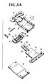
- an adjustable fastener is of the form of an adjustable buckle composed of male and female members coupled together.
- the female member of the adjustable buckle is composed of a flat hollow socket or sleeve 1 of a substantially rectangular shape having a longitudinal guide channel 4 extending from an end of the sleeve 1 and terminating short of an opposite end of the sleeve 1.
- the sleeve 1 is composed of a recessed rectangular top plate 2 and a flat rectangular back plate 3 assembled with the top plate 2 to close a recessed side of the top plate 2.
- the top plate 2 has a longitudinal recess substantially constituting the guide channel 4, and a transverse guide groove 6 extending perpendicular to and opening toward the longitudinal guide channel 4.
- the sleeve 1 further has a connecting portion 5 integrally formed with the top plate 2 at the opposite end of the sleeve 1, and a pair of openings 7 contiguous to opposite ends, respectively, of the transverse guide groove 6.
- the male member of the adjustable buckle comprises a flat plug 8 which can be coupled with the sleeve 1.
- the plug 8 includes a substantially rectangular body 9, a narrow locking leg 10 extending from an end of the body 9, and a connecting portion 11 at an opposite end of the body 9.
- the locking leg 10 and the body 9 are slidably received in the guide channel 4 in the sleeve 1 while the C-shaped ring connector 11 is disposed outside the sleeve 1.
- the plug 8 further has a pair of rows of first and second teeth 12, 13 disposed on and extending along opposite longitudinal edges of the locking leg 10.
- the first and second teeth 12, 13 are in the form of saw-teeth each having a straight edge extending transverse to the locking leg 10 and facing toward the connecting portion 11, and an inclined edge facing away from the connecting portion 11.
- the first and second teeth 12, 13 are not used at the same time, but either one of them is used depending upon selection determined by the mode of attachment of the adjustable fastener to an article, as described later on. It is therefore possible to omit one row of saw-teeth 12 or 13 when the mode of attachment of the adjustable fastener is fixed.
- the plug 8 has in its underside an elongate longitudinal recess 14 in which a stopper projection 15 on an inner surface of the back plate 3 is received for holding the plug 8 in position against accidental removal from the sleeve 1.
- the recess 14 and the stopper projection 15 may be omitted when the sleeve 1 and the plug 8 are intended for releasable coupling.
- the connecting portions 5, 11 of the sleeve 1 and the plug 8 are formed of generally C-shaped ring connectors.
- the C-shaped ring connectors 5, 11 may be replaced with O-ring connectors.
- the illustrated adjustable buckle is used on a pair of trousers for adjustably connecting a loose end of a waistband to adjust the effective length of the waistband, hence the sleeve 1 and the plug 8 are bent or curved so as to substantially conform to a curve of the waistband when the user wears the trousers.
- the adjustable buckle further includes a locking member 16 slidably received within the guide groove 6 and movable in a direction perpendicular to the direction of movement of the plug 8.
- the locking member 16 has a hat-like shape in cross section and has a pair of pusher heads 17, 18 at opposite ends thereof, as shown in Figure 4.
- the locking member 16 is disposed astride the locking leg 10 of the plug 8, with the pusher heads 17, 18 disposed in registry with the respective openings 7 in the sleeve 1.
- the locking member 16 further has a pair of rows of first and second locking projections 19, 20 disposed on and along confronting inner edges of the respective pusher heads 17, 18 for locking engagement with the teeth 12, 13 on the plug 8.
- the locking projections 19, 20 comprise saw-teeth complementary in shape with the saw-teeth 12, 13 on the plug 8.
- the locking member 16 further has a pair of parallel spaced longitudinal recesses 21, 22 extending from opposite ends in staggered relation to one another.
- a compression coil spring 23 is disposed in the recess 21 and acts between the sleeve 1 and the locking member 16 for urging the latter in a direction to retain the locking saw-teeth 19 in locking engagement with the saw-teeth 12 on the plug 8. In this locking position, the pusher head 18 projects from the corresponding opening 7 to the outside of the sleeve 1.
- one row of saw-teeth 12 or 13 on the plug 8 and one row of locking saw-teeth 19 or 20 on the locking member 16 one of the openings 7 in the sleeve 1 and one of the recesses 21 or 22 in the locking member 16 can be omitted depending on the mode of application of the adjustable buckle.
- the stopper 24 is disposed within the guide groove 6 adjacent to the pusher head 17, as shown in Figure 4.
- the stopper 24 thus provided is engageable with the locking member 16 to limit movement of the locking member 16 in a direction opposite to the direction of the force of the spring 23.
- the stopper 24 may be formed integrally with the sleeve 1 if the adjustable buckle is used in the fixed mode of application in which the pusher head 18 projects outwardly from the sleeve 1.
- the stopper 24 is disposed adjacent to the pusher head 18 to limit movement of the locking member 16 within the predetermined range when the pusher head 17 is depressed.
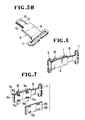
- the connecting portion in the form of a C-shaped connector ring 5 may be replaced with a plurality (four in the illustrated embodiment) of prongs 5a projecting from a rectangular back plate 3a of a sleeve 1a, the prongs 5a being disposed adjacent to the respective corners of the back plate 3a.
- the prongs 5a For attachment of the sleeve 1a to an article such as a pair of trousers, the prongs 5a pierce the fabric of the trousers and openings 25 in a retainer plate 26 thereon and are clinched to the retainer plate 26.
- the retainer plate 26 is curved at the same radius of curvature as the back plate 3a of the sleeve 1a.
- the retainer plate 26 may be replaced with a flat hollow retainer 26′ shown in Figures 8 and 9.
- the hollow retainer 26′ is formed from an elongate sheet of metal longitudinally bent or folded over itself with an elongate guide slot 27 defined between upper and lower plates of the folded sheet metal.
- the retainer 26′ includes a pair of inclined guide flaps 28 extending along opposite longitudinal edges of the lower plate and projecting outwardly therefrom for guiding the prongs 5a smoothly therealong into the guide slot 27 when the prongs 5a are clinched with the retainer 26′. Then, the guide flaps 28 are bent inwardly against the prongs 5a. Since the guide slot 27 has a width W1 substantially the same as or slightly larger than the maximum distance W2 ( Figure 7) between two adjacent prongs 5a, the prongs 5a are held firmly in the retainer 26′ without wobbling.
- the C-shaped ring connector 5 of the sleeve 1 is connected to a first belt or strap 31 secured by sewing stitches to an upper part 29 of the waistband, while the C-shaped ring connector 11 of the plug 8 is connected to a second belt or strap 32 secured by sewing stitches to a lower part 30 of the waistband,
- the adjustable buckle thus attached operates as follows.
- the push head 18 of the locking member 16 is pushed by the user's finger against the force of the spring 23 to cause the locking saw-teeth 19 to disengage from the saw-teeth 12 on the plug 8.
- the plug 8 is moved along the guide channel 4 toward a desired position in the sleeve 1.
- the user releases the locking member 16 so that the locking member 16 is automatically returned to its normal position under the force of the spring 23.
- the locking saw-teeth 19 on the locking member 16 again engage the saw-teeth 12 on the plug 8 thereby holding the plug 8 in position against movement relative to the sleeve 1.
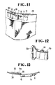
- the adjustable buckle may be attached to the waistband in a different manner such as shown in Figure 11, in which the C-shaped ring connector 5 of the sleeve 1 is connected to the second strap 32 while the C-shaped ring connector 11 of the plug 8 is connected to the first strap 31.
- the pusher head 17 ( Figure 1) of the locking member 16 is disposed outside of the sleeve 1. This arrangement is achieved by displacing the spring 23 from the recess 21 to the recess 22 in the locking member 16 and placing the stopper 24 adjacent to the pusher head 18.
- Figures 12 and 13 show a modified sleeve 1b having a stepped C-shaped ring connector 5b extending in a place which is offset outwardly from the back plate of the sleeve 1b.
- the stepped C-shaped ring connector 5b passes through a slit 33 in the lower part 30 of the waistband from the front side to the rear side of the lower part 30.
- the adjustable fastener composed of a thin flat sleeve 1 and a flat plug 8 slidably received therein,is low in profile and sightly in appearance. Furthermore, the plug 8 and the locking member 16 received in the sleeve 1 are substantially free from damage.
- the adjustable fastener is rigid enough to withstand force and pressure applied when ironing the trousers. With the provision of two rows of saw-teeth 12, 13, two rows of locking saw-teeth 19, 20, two recesses 21 and a stopper 24 structurally separated from the sleeve 1, the mode of application of the adjustable fastener can be changed only by changing the position of the spring 23 and the stopper 24.
Landscapes
- Engineering & Computer Science (AREA)
- Textile Engineering (AREA)
- Buckles (AREA)
- Slide Fasteners (AREA)
- Details Of Garments (AREA)
- Clamps And Clips (AREA)
- Mutual Connection Of Rods And Tubes (AREA)
Claims (10)
- Einstellbarer Verschluß zum Verbinden eines ersten Teils und eines zweiten Teils, wobei der einstellbare Verschluß umfaßt: eine flache hohle Hülse (1) mit einem längsgerichteten Führungskanal (4), der sich von einem Ende der Hülse (1) erstreckt, einer Führungsnut (6), die quer zu dem Führungskanal (4) verläuft und in diesen mündet, und einem ersten Verbindungsbereich (5) zur Befestigung an dem ersten Teil;
einen Stecker (8) mit einem flachen Körper (9), der in den Führungskanal (4) verschiebbar einsetzbar ist, ersten und zweiten Reiben von Zähnen (12, 13), die sich entlang den gegenüberliegenden Längsrändern des Körpers (9) erstrecken, und einem zweiten Verbindungsbereich (11), der an einem Ende des Körpers (9) zur Befestigung an dem zweiten Teil angeordnet ist;
Verriegelungsmittel, die in der Führungsnut (6) verschiebbar angeordnet sind zum Verriegeln des Steckers (8) in der Hülse (1);
und Federmittel (23), die in der Hülse (1) gehalten sind;
dadurch gekennzeichnet, daß die Verriegelungsmittel ein Verriegelungsteil (16), das in der Führungsnut (6) verschiebbar angeordnet ist, erste und zweite Druckköpfe (17, 18), die an gegenüberliegenden Enden des Verriegelungsteils (16) vorgesehen sind, und erste und zweite Sperrvorsprünge (19, 20) umfassen, die neben dem ersten bzw. zweiten Druckkopf (17, 18) angeordnet sind, wobei die ersten und zweiten Sperrvorsprünge (19, 20) mit den ersten und zweiten Zähnen (12, 13) lösbar in Eingriff bringbar sind;
daß die Federmittel (23) normalerweise wirksam sind, um einen der ersten und zweiten Sperrvorsprünge (19, 20) mit einem zugeordneten ersten oder zweiten Zahn (12, 13) in Sperreingriff zu halten, um dadurch den Stecker (8) in der Hülse (1) zu verriegeln, wobei der andere der ersten und zweiten Sperrvorsprünge mit dem zugeordneten anderen ersten und zweiten Zahn (12, 13) nicht in Verriegelungseingriff steht, wobei die Federmittel (23) das Verriegelungsteil (16) so belasten, daß einer der ersten und zweiten Druckköpfe (17, 18) von der Hülse (1) nach außen ragt, wenn der Stecker (8) in der Hülse (1) verriegelt ist;
und daß das Verriegelungsteil (16) gegen die Kraft der Federmittel (23) längs der Führungsnut (6) bewegbar ist, wenn einer der ersten und zweiten Druckköpfe (17, 18), der aus der Hülse (1) herausragt, gedrückt wird, um den besagten einen der ersten und zweiten Sperrvorsprünge (19, 20) mit dem zugeordneten einen ersten und zweiten Zahn (12, 13) außer Eingriff zu bringen und dadurch den Stecker (8) von der Hülse (1) zu trennen. - Einstellbarer Verschluß nach Anspruch 1, wobei das Verriegelungsteil (16) eine Ausnehmung (21) hat, die von einem gegenüberliegenden Ende des Verriegelungsteils (16) ausgeht und kurz vor dem besagten einen Ende des Verriegelungsteils (16) endet, wobei die Federmittel (23) aus einer in dieser Ausnehmung (21) angeordneten Schraubendruckfeder bestehen.
- Einstellbarer Verschluß nach Anspruch 1, wobei das Verriegelungsteil (16) eine erste Ausnehmung (21) hat, die von einem Ende des Verriegelungsteils ausgeht und am gegenüberliegenden Ende des Verriegelungsteils (16) endet, und eine zweite Ausnehmung (22) hat, die von einem gegenüberliegenden Ende des Verriegelungsteile (16) ausgeht und kurz vor dem besagten einen Ende des Verriegelungsteils (16) endet, wobei die Federmittel (23) aus einer Schraubendruckfeder bestehen, die in einer der ersten und zweiten Ausnehmungen (21, 22) angeordnet ist.
- Einstellbarer Verschluß nach einem der vorhergehenden Ansprüche, wobei die Zähne (12, 13) an dem Stecker (8) aus Sägezähnen bestehen, die jeweils eine quer zu der Bewegungsrichtung des Steckers (8) verlaufende gerade Kante und eine von dem besagten einen Ende der Hülse abgekehrte geneigte Kante haben, wobei der Sperrvorsprung (19, 20) des Verriegelungsteils (16) aus einem Sägezahn besteht, der eine zu dem Sägezahn (12, 13) des Steckers (8) komplementäre Kontur hat.
- Einstellbarer Verschluß nach einem der vorhergehenden Ansprüche und ferner umfassend einen Anschlag (24), der in der Führungsnut (6) nahe dem anderen der ersten und zweiten Druckköpfe (17, 18) angeordnet und mit dem Verriegelungsteil (16) in Eingriff bringbar ist, um die Bewegung des Verriegelungsteils (16) zu begrenzen, wenn der eine der ersten und zweiten Druckköpfe (17, 18) gedrückt wird, um dadurch den anderen der ersten und zweiten Sperrvorsprünge (19, 20) am Eingriff mit dem zugeordneten anderen Zahn (12, 13) zu hindern, wenn der eine der ersten und zweiten Druckköpfe (17, 18) gedrückt wird.
- Einstellbarer Verschluß nach einem der vorhergehenden Ansprüche, wobei die Hülse (1) oder der Stecker (8) eine sich parallel zur Bewegungsrichtung des Steckers (8) erstreckende Führungsausnehmung (14) hat, wobei der Stecker (8) oder die Hülse (1) einen Anschlagvorsprung (15) hat, der in die Führungsausnehmung (14) verschiebbar eingreift, um die Hülse (1) und den Stecker (8) gegen eine versehentliche Trennung im zusammengefügten Zustand zu halten.
- Einstellbarer Verschluß nach einem der vorhergehenden Ansprüche, wobei der Verbindungsbereich (5) der Hülse (1) aus einem im wesentlichen C-förmigen Ringverbinder besteht, der am gegenüberliegenden Ende der Hülse (1) angeordnet ist, wobei der Verbindungsbereich (11) des Steckers (8) aus einem im allgemeinen C-förmigen Ringverbinder besteht.
- Einstellbarer Verschluß nach einem der vorhergehenden Ansprüche, wobei der Verbindungsbereich (5a) der Hülse (1a) aus mehreren Dornen besteht, die von einer Unterseite der Hülse (1a) abstehen, um das erste Teil zu durchstoßen, wobei der Verbindungsbereich (11) des Steckers (8) aus einem im wesentlichen C-förmigen Ringverbinder besteht, wobei der Verbindungsbereich der Hülse (1a) ferner ein Gegenstück (26, 26′) aufweist, um das die Dorne herumgebogen werden, wobei das erste Teil zwischen der Hülse (1a) und dem Gegenstück (26, 26′) angeordnet ist.
- Einstellbarer Verschluß nach Anspruch 8, wobei das Gegenstück (26) mehrere Öffnungen (25) für den Durchgang der zugeordneten Dorne (5a) aufweist, wenn die Dorne (5a) um das Gegenstück (26) herumgebogen werden.
- Einstellbarer Verschluß nach Anspruch 8, wobei das Gegenstück (26) hohl ausgebildet ist und einen inneren Schlitz (27) und zwei geneigte Führungsklappen (28) aufweist, die neben den gegenüberliegenden offenen Enden des Schlitzes (27) angeordnet sind, um die Dorne (5a) in den Schlitz (27) einzuführen, wenn die Dorne (5a) mit dem Gegenstück (26′) verklemmt werden.
Applications Claiming Priority (2)
| Application Number | Priority Date | Filing Date | Title |
|---|---|---|---|
| JP63135133A JPH0655170B2 (ja) | 1988-05-31 | 1988-05-31 | 締付け調節具 |
| JP135133/88 | 1988-05-31 |
Publications (3)
| Publication Number | Publication Date |
|---|---|
| EP0345014A2 EP0345014A2 (de) | 1989-12-06 |
| EP0345014A3 EP0345014A3 (en) | 1990-03-28 |
| EP0345014B1 true EP0345014B1 (de) | 1992-10-07 |
Family
ID=15144580
Family Applications (1)
| Application Number | Title | Priority Date | Filing Date |
|---|---|---|---|
| EP89305433A Expired - Lifetime EP0345014B1 (de) | 1988-05-31 | 1989-05-30 | Einstellbarer Verschluss |
Country Status (11)
| Country | Link |
|---|---|
| US (1) | US4916779A (de) |
| EP (1) | EP0345014B1 (de) |
| JP (1) | JPH0655170B2 (de) |
| KR (1) | KR910002664B1 (de) |
| AU (1) | AU598419B2 (de) |
| BR (1) | BR8902941A (de) |
| CA (1) | CA1301719C (de) |
| DE (1) | DE68903132T2 (de) |
| ES (1) | ES2034634T3 (de) |
| HK (1) | HK194895A (de) |
| MY (1) | MY104027A (de) |
Families Citing this family (31)
| Publication number | Priority date | Publication date | Assignee | Title |
|---|---|---|---|---|
| JP2750346B2 (ja) * | 1988-05-18 | 1998-05-13 | トヨタ自動車株式会社 | 有段自動変速機の変速制御方法 |
| CA2027720A1 (en) * | 1990-10-16 | 1992-04-17 | Claude Mauffette | Belt |
| US5374262A (en) * | 1992-12-30 | 1994-12-20 | Kimberly-Clark Corporation | Adjustable garment attachment system |
| US5304162A (en) * | 1992-12-30 | 1994-04-19 | Kimberly-Clark Corporation | Garment and pleated, adjustable strap member therefor |
| JPH074248U (ja) * | 1993-06-16 | 1995-01-20 | アップリカ▲葛▼西株式会社 | 乳母車 |
| US5427562A (en) * | 1993-09-17 | 1995-06-27 | Hwang; Ying-Teh | Brassiere |
| FR2732866B1 (fr) * | 1995-04-11 | 1997-05-23 | Smh Management Services Ag | Maillon reglable pour bracelet a maillons |
| US5873635A (en) * | 1997-01-14 | 1999-02-23 | Indiana Mills & Manufacturing, Inc. | Child seat harness clip with web lock |
| EP1072207A1 (de) * | 1999-07-19 | 2001-01-31 | Jacques Malsoute | Hosengürtel mit dehnbarem Verschluss |
| US7254872B2 (en) * | 2005-06-16 | 2007-08-14 | Amara Ross | Belt buckle |
| DE202005013696U1 (de) * | 2005-08-30 | 2005-11-17 | Knauer, Hans-Georg | Rastverschluss bei Gurtbändern |
| ITTO20060530A1 (it) * | 2006-07-19 | 2008-01-20 | Nat Molding Europ S R L | Struttura di fibbia |
| CN101568270B (zh) * | 2007-02-19 | 2012-11-07 | 伊利诺斯工具制品有限公司 | 带扣组件 |
| US20090283729A1 (en) * | 2008-05-06 | 2009-11-19 | Carlson Jesse P | Extendable handle leverage ratchet |
| US8181319B2 (en) * | 2009-03-30 | 2012-05-22 | D B Industries, Inc. | Buckle |
| US8925977B2 (en) * | 2009-10-09 | 2015-01-06 | Mueller International, Llc | Simplified low insertion force sealing device capable of self restraint and joint deflection |
| US8857861B2 (en) * | 2009-10-12 | 2014-10-14 | Mueller International, Llc | Self-restrained pipe joint system |
| CA2799588A1 (en) | 2010-05-24 | 2011-12-01 | Mueller International Llc | Simplified low insertion force sealing device capable of self restraint and joint deflection |
| US8683665B2 (en) * | 2011-01-10 | 2014-04-01 | Duraflex Hong Kong Limited | Ratchet adjustment system |
| US20120174291A1 (en) * | 2011-01-10 | 2012-07-12 | Duraflex Hong Kong Limited | Ratchet adjustment system |
| US20130117987A1 (en) * | 2011-11-16 | 2013-05-16 | Media Planner, Inc. | System and Method for Using and Decorating a Belt Assembly |
| US20130167288A1 (en) * | 2011-12-28 | 2013-07-04 | Lippert Components, Inc. | Belt adjustment system |
| KR101274672B1 (ko) * | 2013-02-21 | 2013-06-17 | 류양석 | 버클 |
| US9277791B2 (en) * | 2014-07-21 | 2016-03-08 | Microsoft Technology Licensing, Llc | Adjustable band mechanism |
| US9993048B2 (en) | 2015-06-10 | 2018-06-12 | D B Industries, Llc | Safety harness connector assembly |
| US11464296B2 (en) | 2017-03-20 | 2022-10-11 | Eric Lee Martin | Slidable button on a monorail track for tightening and loosening of a garment |
| WO2018175345A1 (en) * | 2017-03-20 | 2018-09-27 | Eric Martin | Garment button with slidable track for tightening and loosening of a garment |
| WO2018201216A1 (en) * | 2017-05-01 | 2018-11-08 | Stayback Fitting Systems Inc. | Garment fitting mechanism and hat incorporating same |
| US11536308B2 (en) | 2018-12-03 | 2022-12-27 | Arrowhead Design and Innovation, LLC | Adjustable fastener system |
| CN111011961A (zh) * | 2019-11-18 | 2020-04-17 | 胡志远 | 自动扣合式皮带装置 |
| CN111238557B (zh) * | 2020-02-11 | 2022-07-29 | 国电南瑞科技股份有限公司 | 一种安全防脱落的输电线路监测终端 |
Family Cites Families (14)
| Publication number | Priority date | Publication date | Assignee | Title |
|---|---|---|---|---|
| FR742939A (de) * | 1933-03-18 | |||
| US1786943A (en) * | 1927-07-13 | 1930-12-30 | Smith & Crosby | Bracelet construction |
| US1744175A (en) * | 1927-09-21 | 1930-01-21 | Harvey Clap & Co | Construction for bracelets and the like |
| US1838463A (en) * | 1927-10-01 | 1931-12-29 | Statham Noel | Adjustable fastening device |
| US1910891A (en) * | 1932-03-17 | 1933-05-23 | North & Judd Mfg Co | Separable fastener |
| US1910892A (en) * | 1932-03-19 | 1933-05-23 | North & Judd Mfg Co | Separable fastener |
| US2495667A (en) * | 1947-02-07 | 1950-01-24 | Ornstein & Sons Corp D | Adjustable clasp |
| US2615218A (en) * | 1950-01-13 | 1952-10-28 | United Carr Fastener Corp | Gripping slider type buckle with fastener member on slider |
| CH286603A (fr) * | 1950-11-16 | 1952-10-31 | S A Kurth Freres | Fermoir pour bracelet. |
| DE2450336A1 (de) * | 1974-10-23 | 1976-04-29 | Armin Schwerdtfeger | Verschluss fuer schmuckartikel in bandform |
| JPS6138888Y2 (de) * | 1979-03-19 | 1986-11-08 | ||
| US4534087A (en) * | 1983-12-01 | 1985-08-13 | Wah Lau | Adjustable buckle |
| JP2990950B2 (ja) * | 1992-05-29 | 1999-12-13 | 株式会社日立製作所 | 渦流ブロワの羽根車 |
| JPH06233882A (ja) * | 1993-02-08 | 1994-08-23 | Juki Corp | 刺繍下絵読取り装置 |
-
1988
- 1988-05-31 JP JP63135133A patent/JPH0655170B2/ja not_active Expired - Lifetime
-
1989
- 1989-05-26 US US07/357,606 patent/US4916779A/en not_active Expired - Lifetime
- 1989-05-26 CA CA000600793A patent/CA1301719C/en not_active Expired - Lifetime
- 1989-05-30 KR KR1019890007263A patent/KR910002664B1/ko not_active IP Right Cessation
- 1989-05-30 EP EP89305433A patent/EP0345014B1/de not_active Expired - Lifetime
- 1989-05-30 DE DE8989305433T patent/DE68903132T2/de not_active Expired - Fee Related
- 1989-05-30 MY MYPI89000740A patent/MY104027A/en unknown
- 1989-05-30 AU AU35846/89A patent/AU598419B2/en not_active Ceased
- 1989-05-30 ES ES198989305433T patent/ES2034634T3/es not_active Expired - Lifetime
- 1989-05-31 BR BR898902941A patent/BR8902941A/pt not_active IP Right Cessation
-
1995
- 1995-12-28 HK HK194895A patent/HK194895A/xx not_active IP Right Cessation
Also Published As
| Publication number | Publication date |
|---|---|
| BR8902941A (pt) | 1990-02-06 |
| KR900017521A (ko) | 1990-12-19 |
| KR910002664B1 (ko) | 1991-05-03 |
| AU598419B2 (en) | 1990-06-21 |
| EP0345014A3 (en) | 1990-03-28 |
| CA1301719C (en) | 1992-05-26 |
| JPH01303102A (ja) | 1989-12-07 |
| ES2034634T3 (es) | 1993-04-01 |
| DE68903132D1 (de) | 1992-11-12 |
| US4916779A (en) | 1990-04-17 |
| EP0345014A2 (de) | 1989-12-06 |
| HK194895A (en) | 1996-01-05 |
| JPH0655170B2 (ja) | 1994-07-27 |
| DE68903132T2 (de) | 1993-02-11 |
| AU3584689A (en) | 1989-12-21 |
| MY104027A (en) | 1993-10-30 |
Similar Documents
| Publication | Publication Date | Title |
|---|---|---|
| EP0345014B1 (de) | Einstellbarer Verschluss | |
| EP0204250B1 (de) | Schnalle | |
| US4821934A (en) | Plastic support clip having a retaining hook for releasably retaining an article within the clip | |
| US5471714A (en) | Device for adjustable attachment of a strap | |
| EP0956784B1 (de) | Gurtanschlussvorrichtung | |
| US4406043A (en) | Belt buckle construction | |
| JPH0431685B2 (de) | ||
| US6321419B1 (en) | Brassiere fastener | |
| EP0169342B1 (de) | Schnalle | |
| EP3810525B1 (de) | Gurtverstellsystem | |
| GB2150632A (en) | Buckles | |
| EP0311042A1 (de) | Schnalle | |
| GB1578302A (en) | Adjustable fastening device | |
| EP0245877B1 (de) | Schnalle | |
| EP0575078B1 (de) | Bandverschluss | |
| EP0343637B1 (de) | Schlüsselhalter | |
| JPH04266705A (ja) | ベルト留め具 | |
| US4945616A (en) | Adjustable closure for overlapping parts | |
| US4827796A (en) | Securement band and connector means therefor | |
| EP0466446A1 (de) | Trennbare zweiteilige Steckschnalle | |
| US4065834A (en) | Watchband | |
| JP2005112147A (ja) | 浮力調整器 | |
| GB2045857A (en) | Adjustable fastener | |
| EP0375379B1 (de) | Schnalle | |
| JPH10327909A (ja) | スライドホック |
Legal Events
| Date | Code | Title | Description |
|---|---|---|---|
| PUAI | Public reference made under article 153(3) epc to a published international application that has entered the european phase |
Free format text: ORIGINAL CODE: 0009012 |
|
| AK | Designated contracting states |
Kind code of ref document: A2 Designated state(s): BE CH DE ES FR GB IT LI NL SE |
|
| PUAL | Search report despatched |
Free format text: ORIGINAL CODE: 0009013 |
|
| AK | Designated contracting states |
Kind code of ref document: A3 Designated state(s): BE CH DE ES FR GB IT LI NL SE |
|
| 17P | Request for examination filed |
Effective date: 19900307 |
|
| 17Q | First examination report despatched |
Effective date: 19910830 |
|
| GRAA | (expected) grant |
Free format text: ORIGINAL CODE: 0009210 |
|
| AK | Designated contracting states |
Kind code of ref document: B1 Designated state(s): BE CH DE ES FR GB IT LI NL SE |
|
| ITF | It: translation for a ep patent filed | ||
| ET | Fr: translation filed | ||
| REF | Corresponds to: |
Ref document number: 68903132 Country of ref document: DE Date of ref document: 19921112 |
|
| PLBE | No opposition filed within time limit |
Free format text: ORIGINAL CODE: 0009261 |
|
| STAA | Information on the status of an ep patent application or granted ep patent |
Free format text: STATUS: NO OPPOSITION FILED WITHIN TIME LIMIT |
|
| 26N | No opposition filed | ||
| REG | Reference to a national code |
Ref country code: CH Ref legal event code: PFA Free format text: YKK CORPORATION |
|
| ITPR | It: changes in ownership of a european patent |
Owner name: CAMBIO RAGIONE SOCIALE;YKK CORPORATION |
|
| REG | Reference to a national code |
Ref country code: FR Ref legal event code: CD |
|
| EAL | Se: european patent in force in sweden |
Ref document number: 89305433.8 |
|
| REG | Reference to a national code |
Ref country code: ES Ref legal event code: PC2A Owner name: YKK CORPORATION |
|
| NLT1 | Nl: modifications of names registered in virtue of documents presented to the patent office pursuant to art. 16 a, paragraph 1 |
Owner name: YKK CORPORATION TE TOKIO, JAPAN. |
|
| REG | Reference to a national code |
Ref country code: GB Ref legal event code: IF02 |
|
| PGFP | Annual fee paid to national office [announced via postgrant information from national office to epo] |
Ref country code: SE Payment date: 20020508 Year of fee payment: 14 Ref country code: FR Payment date: 20020508 Year of fee payment: 14 |
|
| PGFP | Annual fee paid to national office [announced via postgrant information from national office to epo] |
Ref country code: ES Payment date: 20020522 Year of fee payment: 14 |
|
| PGFP | Annual fee paid to national office [announced via postgrant information from national office to epo] |
Ref country code: NL Payment date: 20020529 Year of fee payment: 14 Ref country code: GB Payment date: 20020529 Year of fee payment: 14 |
|
| PGFP | Annual fee paid to national office [announced via postgrant information from national office to epo] |
Ref country code: CH Payment date: 20020531 Year of fee payment: 14 |
|
| PGFP | Annual fee paid to national office [announced via postgrant information from national office to epo] |
Ref country code: DE Payment date: 20020610 Year of fee payment: 14 |
|
| PGFP | Annual fee paid to national office [announced via postgrant information from national office to epo] |
Ref country code: BE Payment date: 20020717 Year of fee payment: 14 |
|
| PG25 | Lapsed in a contracting state [announced via postgrant information from national office to epo] |
Ref country code: GB Free format text: LAPSE BECAUSE OF NON-PAYMENT OF DUE FEES Effective date: 20030530 |
|
| PG25 | Lapsed in a contracting state [announced via postgrant information from national office to epo] |
Ref country code: SE Free format text: LAPSE BECAUSE OF NON-PAYMENT OF DUE FEES Effective date: 20030531 Ref country code: LI Free format text: LAPSE BECAUSE OF NON-PAYMENT OF DUE FEES Effective date: 20030531 Ref country code: ES Free format text: LAPSE BECAUSE OF NON-PAYMENT OF DUE FEES Effective date: 20030531 Ref country code: CH Free format text: LAPSE BECAUSE OF NON-PAYMENT OF DUE FEES Effective date: 20030531 Ref country code: BE Free format text: LAPSE BECAUSE OF NON-PAYMENT OF DUE FEES Effective date: 20030531 |
|
| BERE | Be: lapsed |
Owner name: *YKK CORP. Effective date: 20030531 |
|
| PG25 | Lapsed in a contracting state [announced via postgrant information from national office to epo] |
Ref country code: NL Free format text: LAPSE BECAUSE OF NON-PAYMENT OF DUE FEES Effective date: 20031201 |
|
| PG25 | Lapsed in a contracting state [announced via postgrant information from national office to epo] |
Ref country code: DE Free format text: LAPSE BECAUSE OF NON-PAYMENT OF DUE FEES Effective date: 20031202 |
|
| EUG | Se: european patent has lapsed | ||
| REG | Reference to a national code |
Ref country code: CH Ref legal event code: PL |
|
| GBPC | Gb: european patent ceased through non-payment of renewal fee |
Effective date: 20030530 |
|
| PG25 | Lapsed in a contracting state [announced via postgrant information from national office to epo] |
Ref country code: FR Free format text: LAPSE BECAUSE OF NON-PAYMENT OF DUE FEES Effective date: 20040130 |
|
| NLV4 | Nl: lapsed or anulled due to non-payment of the annual fee |
Effective date: 20031201 |
|
| REG | Reference to a national code |
Ref country code: FR Ref legal event code: ST |
|
| REG | Reference to a national code |
Ref country code: ES Ref legal event code: FD2A Effective date: 20030531 |
|
| PG25 | Lapsed in a contracting state [announced via postgrant information from national office to epo] |
Ref country code: IT Free format text: LAPSE BECAUSE OF NON-PAYMENT OF DUE FEES;WARNING: LAPSES OF ITALIAN PATENTS WITH EFFECTIVE DATE BEFORE 2007 MAY HAVE OCCURRED AT ANY TIME BEFORE 2007. THE CORRECT EFFECTIVE DATE MAY BE DIFFERENT FROM THE ONE RECORDED. Effective date: 20050530 |