EP0345003A2 - Wetterbeständigkeitsprüfung - Google Patents
Wetterbeständigkeitsprüfung Download PDFInfo
- Publication number
- EP0345003A2 EP0345003A2 EP89305405A EP89305405A EP0345003A2 EP 0345003 A2 EP0345003 A2 EP 0345003A2 EP 89305405 A EP89305405 A EP 89305405A EP 89305405 A EP89305405 A EP 89305405A EP 0345003 A2 EP0345003 A2 EP 0345003A2
- Authority
- EP
- European Patent Office
- Prior art keywords
- sample
- test
- dew
- weather resistance
- ultraviolet radiation
- Prior art date
- Legal status (The legal status is an assumption and is not a legal conclusion. Google has not performed a legal analysis and makes no representation as to the accuracy of the status listed.)
- Granted
Links
Images


Classifications
-
- G—PHYSICS
- G01—MEASURING; TESTING
- G01N—INVESTIGATING OR ANALYSING MATERIALS BY DETERMINING THEIR CHEMICAL OR PHYSICAL PROPERTIES
- G01N17/00—Investigating resistance of materials to the weather, to corrosion, or to light
-
- G—PHYSICS
- G01—MEASURING; TESTING
- G01N—INVESTIGATING OR ANALYSING MATERIALS BY DETERMINING THEIR CHEMICAL OR PHYSICAL PROPERTIES
- G01N17/00—Investigating resistance of materials to the weather, to corrosion, or to light
- G01N17/004—Investigating resistance of materials to the weather, to corrosion, or to light to light
Definitions
- the present invention relates to a method of and apparatus for conducting weather resistance tests, and, more particularly to a method of and an apparatus for weather resistance testing of plastics, paint, ink, pigment, fibre and the like by which the results obtained can satisfactorily simulate outdoor natural deterioration.
- a weather meter in accordance with any of the Japanese industrial standards (JIS) B7751 to 7754 is generally used.
- Each of the weather meters of the types mentioned above comprise a light source, such as a carbon arc lamp or a xenon arc lamp, and beams from this light source are directed at the samples. As a result, this allows an accelerated weathering test to be carried out.
- the intensity of the ultraviolet radiation from the light source of the above-described type of weather meter to be applied to the samples is, in general, limited to an unsatisfactory level of substantially 6mW per 100 mm2 of the surface of the sample to be tested. Therefore, it takes several hundred hours or longer to measure or evaluate the characteristics of the ultraviolet irradiation-enhanced deterioration which will occur to equate with the deterioration caused by the sun's rays in one year.
- weather meters described in Japanese Laid-Open Patent Applications Nos. 60-117128 and 60-117129 serve as a pre-weather meter for performing a pre-weather resistance test, which allows ultraviolet ray deterioration to be evaluated in a significantly shortened time, for example, in one tenth or less of the time taken in a conventional test period of time and which involves means for applying to the samples of each batch intense ultraviolet radiation of substantially 50mW or more per 100 mm2 of the surface of the sample to be tested by using a metal halide lamp, before having the samples subjected to the weather meter.
- the weather resistance test is conducted under physical conditions similar to the actual conditions to which the samples, such as plastics or paint are subjected.
- the sample In particular at night, not only is the sample subjected to a state in which no sun rays are applied and of low temperatures but also it can be readily brought to a dew condensed state due to the low temperatures at night.
- the weather resistance test or its pre-test it is preferable for the weather resistance test or its pre-test to be made under such dew condensation conditions in order to obtain test results which can simulate the natural outdoor deterioration.
- a method of providing an actual dew condensation state for samples by adjusting the temperature of the sample and both the temperature and the humidity of the ambient air surrounding it has been conceived, as described in Japanese Laid-Open Patent Application No. 62-297744.
- the weather meter described in this publication is arranged in such a manner that temperature adjusting means is provided for a sample holder and a humidifier is disposed in a chamber of the region in which the thus-provided sample holder is disposed.
- thermoelectric cooling element As means to form dew condensation on the surface of the sample, a method of spraying cooling water onto the reverse side of the sample, has been disclosed, and another method is also described in Japanese Laid-Open Patent Application No. 58-90146 in which the sample is cooled down by thermoelectric cooling element.
- Figs. 10A and 10B of the accompanying drawings are microphotographs of the surface of the sample when the above-described dew condensation process is added to the accelerated weathering test in which the sample is irradiated with ultraviolet light.
- Fig. 10A is a metallurgaical microphotograph, enlarged by 200 times, of the surface of the sample which has not been subjected to the test as yet, while Fig. 10B is a microphotograph, enlarged by 200 times, of the surface of the same sample which has been subjected to the weather resistance test for 50 hours.
- the above-described phenomenon occurs particularly significantly when this dew condensation process is added to the above-described accelerated weathering test in which the intensity of the ultraviolet radiation to be applied is considerably strong.
- spot patterns can be caused for the following reason: impurities are contained in the condensed dew and appear on the surface of the sample during the dew condensation process or substances extracted from the sample due to the dew condensation adhere to the surface of the sample; and then the extraneous matter on the surface of the sample is baked on this surface of the sample due to the lens effect of the residual condensed dew during the application of the ultraviolet radiation after the dew condensation process; as a result, the above-described spot pattern can be generated.
- an object of the present invention is to provide a method of and an apparatus for conducting a weather resistance test capable of overcoming the above-described problems experienced with the previously described weather resistance tests in which the dew condensation process is added, whereby no spot pattern or colour change can be generated, and satisfactory test results, which satisfactorily simulate the outdoor natural deterioration results, can be obtained even if the dew condensation process is added to the weather resistance test.
- a method of conducting weather resistance tests includes a process for applying to a sample, ultraviolet rays from an artificial light source, a process for condensing dew on the surface of this sample, and a process for again applying ultraviolet rays to the above-described sample after the process for condensing dew, the method comprising: a process for washing the surface of the sample with a cleaner which is added at least between the process for condensing the dew on the surface of the sample after the process for applying ultraviolet rays and the process for again applying ultraviolet rays after the process for condensing dew.
- impurities adhered to the surface of the sample or substances extracted on the surface of the sample during the dew condensation process can be washed and removed by the cleaner since the process for washing the surface of the sample with a cleaner is added at least between the process for condensing dew on the surface of the sample after the process for applying ultraviolet rays and the process for again applying the ultraviolet rays after the process for condensing dew. Therefore, these substances cannot be baked onto the surface of the sample in the ensuing process of applying ultraviolet rays. As a result, generation of the spot pattern on the surface of the sample can be effectively prevented, and thereby the excessive colour change on the surface of the sample can be prevented.
- An apparatus for weather resistance tests comprises means for holding a sample, means for applying ultraviolet rays to the sample, means for condensing dew on the surface of the sample, means for washing the surface of the sample with a cleaner, and means for controlling the operation of each of the above-described means.
- FIG. 1 is a schematic view which illustrates an embodiment of an apparatus for conducting weather resistance tests according to the present invention.
- a light source 1 comprises a metal halide lamp exhibiting considerably great energy in the wavelength range for example, from 300 to 450nm, a filter for restricting the wavelength region to 300 to 450 nm, a water cooling jacket, and so on.
- This light source 1 is accommodated in a reflecting plate comprising a dome-shaped main reflecting plate 2 for parallel beams and a sub-reflecting plate 3 for parallel beams.
- a shield plate 4 is made of quartz glass through which ultraviolet rays can pass and which is capable of separating the sample chamber 5 from the light source portion.
- a sample holder 7 to which a sample 6 is attached is disposed in the sample chamber 5, and a temperature adjusting means (omitted from illustration), such as a water cooling means or thermoelectric cooling means is also provided for this sample holder 7.
- An air blowing nozzle 8 maintains the temperature of the sample at a predetermined value by blowing air at a predetermined temperature onto the sample 6 attached to the sample holder 7.
- a humidifying tank 9 humidifies the sample chamber 5 in which a heater l0 for heating the humidifying tank 9 is provided.
- Spray nozzles 11a and 11b are for spraying a cleaning agent on to the sample 6 attached to the sample holder 7.
- Water, a surface active agent, water containing air, alcohol or the like can be employed as a cleansing fluid to serve as the cleaning agent.
- the sample holder 7 is disposed such that it is inclined by, for example at 15 o , for the purpose of preventing stagnancy of sprayed cleaning agent and of making the sprayed cleansing fluid flow downwards.
- the light source portion 1 is inclined and is attached to the sample chamber 5.
- the sample chamber 5 is further provided with a temperature detector and so on (omitted from illustration).
- Pipes 12 are arranged to be connected to the spray nozzles 11a and 11b.
- An electromagnetic valve 13 controls the delivery of cleansing fluid supplied to a cleansing supply port.
- a control device 15 controls the light source 1, the air blowing nozzle 8, the heater 10 in the humidifying tank 9, the electromagnetic valve 13, and the temperature adjusting means provided for the sample holder 7 in accordance with a predetermined process.
- the sample 6 is placed on the sample holder 7, the light source 1 is turned on and the sample is first subjected to ultraviolet radiation for a predetermined time, for example, for 4 hours.
- the temperature of the sample 6 is maintained at a predetermined value (40 o to 100 o C ⁇ 1.0 o C) by air injected by the blowing nozzle 8 in response to a detection signal supplied from the temperature detector (omitted from the illustration).
- the temperature of the sample holder 7 is lowered by the temperature adjusting means (omitted from illustration) provided for the sample holder 7 to a value below its dew point in response to the detection signal supplied from the temperature detector.
- steam is generated by heating the humidifying tank 9 as to humidify the sample chamber 5 to a predetermined humidity.
- the electromagnetic valve 13 is actuated by a control signal supplied from the control device 15, and the spray nozzles 11a and 11b are operated to inject the cleansing fluid on to the sample 6.
- the light source 1 is again turned on so that the sample 6 is again subjected to ultraviolet radiation. Then, the above-described process is repeated.
- the weather resistance test By conducting the weather resistance test in the manner as described above, the conditions which significantly simulate the dew condensation state at night in the outdoor exposure state can be made for the sample. In addition, the generation of the spot pattern on the surface of the sample and the excessive change in colour of the surface of the sample can be prevented. As a result, the results of weather resistance tests which can significantly simulate the natural deterioration can be obtained in a significantly short time period.
- the washing process is added between the dew condensation process and the ensuing ultraviolet irradiation process, it may be further added after the application of ultraviolet radiation but before the ensuing next dew condensation process. In this case, a further significant effect in prevention of generation of the spot pattern and in prevention of the significant colour change can be obtained. In addition, this washing process may be effectively added in the dew condensation process.
- the number and the positions of the spray nozzles are not so limited.
- the number and distribution of the nozzles may be optionally determined on the basis of the shape, size or the like of the sample holder.
- a means arranged to spray the surface of the sample with hot steam can be employed.
- an ultrasonic washer may also be used.
- light source used metal halide lamp 4 kW; irradiation wavelength: 300 to 450 nm; temperature of the black panel (when ultraviolet rays are applied): 63 o C ⁇ 3 o C; intensity of ultraviolet radiation on the surface of the sample: 100 ⁇ 5mW per 100 mm2; humidity in the sample chamber at the time of dew condensation: 95% or higher; temperature of the sample at the time of dew condensation: 30 o C; application of ultraviolet radiation and dew condensation cycle: ultraviolet radiation is applied for 4 hours, dew condensation for 1 hour; washing period: 30 seconds after the application of ultraviolet radiation and 30 seconds after the dew condensation; cleaning agent: ion exchange water; temperature of the cleaning agent: 20 o C; quantity of the cleaning agent to be sprayed: 9 ml per 100 mm2 of the surface of the sample; pressure of the cleaner injected: 1.47 bar (1.5 kg/cm2).
- light source used sunshine carbon arc lamp; irradiation wavelength: 280 to 1400 nm; temperature of the black panel: 63 ⁇ 3 o C; intensity of ultraviolet radiation at the surface of the sample: 5 mW per 100 mm2.
- zenon arc lamp 3.5 kW irradiation wavelength: 300 to 1400 nm
- temperature of the black panel 63 ⁇ 3 o C
- intensity of ultraviolet radiation on the surface of the sample 2.3 mW per 100 mm2.
- time period 12 months from May 1987 to April 1988; location: Matsudo city, Chiba prefecture, Japan.
- Test conditions for reference example 2 (a process for water is added after the ultraviolet ray irradiation process)
- metal halide lamp 4 kW metal halide lamp 4 kW
- irradiation wavelengh 300 to 450 nm
- temperature of the black panel 63 o C ⁇ 3 o C
- intensity of ultraviolet radiation on the surface of the sample 100 ⁇ 5mW per 100 mm2
- temperature of the liquid in which the sample is dipped 24 o C
- application of ultraviolet radiation and dipping cycle application for 4 hours, dipping for 1 hour;
- Powder mixed in accordance with the above-described composition manner was kneaded in a heat roll at 160 to 170 o C for 5 minutes.
- the thus obtained raw sheet was pressed at 190 to 195 o C for 10 minutes.
- the thus-obtained pressed sheet had been cooled down, the same was made into a sheet substantially 1.0 mm thick to serve as samples.
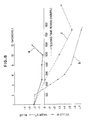
- Curve a shown in Fig. 2 illustrates change in the gloss retention rate in the outdoor exposure test. As is shown, it is rapidly lowered to 20% in 8 months from the start of the test, whereafter it does not display any further significant change.
- Curve a shown in Fig. 2 illustrates change in the gloss retention rate in the outdoor exposure test. As is shown, it is rapidly lowered to 20% in 8 months from the start of the test, whereafter it does not display any further significant change.
- the sunshine weather-meter (conventional example 1)
- curve b shown in Fig. 3 With the zenon weather-meter (conventional example 2), a substantially straight change is displayed as designated by curve c in the same drawing. It is apparent that it takes 600 to 800 hours for both of the above-described tests to have the gloss retention rate lowered to 20%.
- the gloss retention rate does not display any significant change after it has been lowered to 50% in a relatively short time of substantially 20 hours after the start of the test as designated by curve d shown in Fig. 4.
- the retention rate is lowered to 20% prior to lapse of test time period of 50 hours as designated by curve e shown in the same figure.
- it takes only substantially one tenth or less of time taken in the conventional examples 1 and 2 for the gloss retention rate of the sample to experience the degree of deterioration which simulates the degree of deterioration realized by 8 months of outdoor exposure.
- value ⁇ E* reaches 20 or more in a relatively short time (substantially 30 hours) as designated by curve d shown in Fig. 6, it is then brought to a saturated or asymtotic state.
- Value ⁇ E* according to the present invention reaches, as designated by curve e shown in this drawing, substantially 15 in 50 hours, and then this curve rises rapidly, displaying a similar tendency to the curve according to the outdoor exposure test.
- value ⁇ E* reaches, as designated by curve f shown in this figure, substantially 10 at most.
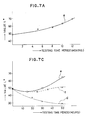
- Figs., 7A, 7B, and 7C the results of measurement of lightners value L* are shown in Figs., 7A, 7B, and 7C.
- Curve a shown in Fig. 7A illustrates change of value L* in the outdoor exposure test, wherein it gradually rises in accordance with time lapse, and value L* reaches 70 in 12 months.
- curves b and c shown in Fig. 7B although value L* does not display a significant change in accordance with testing time lapse in the conventional examples 1 and 2, it is slightly lowered. As is shown, the completely different tendency from the results obtained in the outdoor exposure test is displayed.
- value L* displays a gradual decrease tendency in the conventional example 3.
- value L* according to the present invention is temporarily lowered in accordance with time lapse as designated by curve e in this drawing, it again rises, and, as is shown, it reaches a deterioration state similar to the same after 12 months of the outdoor exposure in a significantly shorter time period of 50 hours.
- the referential example 2 displays, similarly to the conventional examples 1 and 2, a tendency in which there is no significant change.
- value b* shows negative values (blue) at first. Then, it temporarily changes to a value in the vicinity of zero, and shows a tendency towards greater negative values.
- value b* is changed to the positive values (yellow) in both the conventional examples 1 and 2. As is shown, a tendency in which the degree of colour change to yellow on the surface of the sample is raised in accordance with time lapse.
- value b* is changed to an extremely large positive value in a short time in accordance with the conventional example 3.
- Value b* obtained by the method according to the present invention is, as designated by curve e shown in this figure, changed temporarily to positive values which display colour change to yellow. However, it again returns to negative vlues after 50 hours have elapsed. As is shown, a similar tendency to that of the outdoor exposure is displayed.
- Referential example 2 shows a tendency, as designated by curve f of this figure, in which value b* is changed, in a short time, to positive values, and then it comes closer to zero.
- Fig.10A is, as described above, a 200 times metallurgical microphotograph of the surface of the sample which has not been subjected to the test as yet.
- Fig.10B is a 200 times metallurgical microphotograph of the surface of the sample which has been subjected to the weather resistance test according to the conventional example 3 for 50 hours.
- Fig.10C is a 200 times metallurgical microphotograph of the surface of the sample which has been subjected to the weather resistance test according to the present invention.
- Fig.10D is a 200 times metallurgical microphotograph of the surface of the sample after it has been subjected to the outdoor exposure test for 12 months.
- a spot pattern is formed on the surface of the sample, according to - the conventional example 3, such spot pattern is avoided on the surface of the sample according to the present invention.
- a similar surface of the sample to that according to the outdoor exposure is obtained.
- the material of the sample used in the tests in accordance with each of the above-described test methods comprises a hard vinyl chloride plate
- substantially the same results were obtained by both the test method according to the present invention and the test method according to the conventional example 3 even if a soft vinyl chloride plate or a plate to which is applied an acrylic paint is used as the sample. Consequently, the method of performing weather resistance tests according to the present invention displays an advantage that generation of spot patterns and excessive colour change on the surface of the sample can be avoided.
- an artificial light source capable of radiating light including ultraviolet radiation of the same intensity as that of the metal halide lamp and including visible radiation and/or infrared radiation may be used.
- a similar effect can be obtained even if the above-described light source of the second type is used.
Landscapes
- Life Sciences & Earth Sciences (AREA)
- Biodiversity & Conservation Biology (AREA)
- Ecology (AREA)
- Environmental & Geological Engineering (AREA)
- Environmental Sciences (AREA)
- Physics & Mathematics (AREA)
- Health & Medical Sciences (AREA)
- Chemical & Material Sciences (AREA)
- Analytical Chemistry (AREA)
- Biochemistry (AREA)
- General Health & Medical Sciences (AREA)
- General Physics & Mathematics (AREA)
- Immunology (AREA)
- Pathology (AREA)
- Testing Resistance To Weather, Investigating Materials By Mechanical Methods (AREA)
Applications Claiming Priority (2)
| Application Number | Priority Date | Filing Date | Title |
|---|---|---|---|
| JP63131627A JP2660721B2 (ja) | 1988-05-31 | 1988-05-31 | 耐候性試験方法及びその装置 |
| JP131627/88 | 1988-05-31 |
Publications (3)
| Publication Number | Publication Date |
|---|---|
| EP0345003A2 true EP0345003A2 (de) | 1989-12-06 |
| EP0345003A3 EP0345003A3 (en) | 1990-05-16 |
| EP0345003B1 EP0345003B1 (de) | 1992-11-19 |
Family
ID=15062471
Family Applications (1)
| Application Number | Title | Priority Date | Filing Date |
|---|---|---|---|
| EP89305405A Expired EP0345003B1 (de) | 1988-05-31 | 1989-05-30 | Wetterbeständigkeitsprüfung |
Country Status (4)
| Country | Link |
|---|---|
| US (1) | US4995273A (de) |
| EP (1) | EP0345003B1 (de) |
| JP (1) | JP2660721B2 (de) |
| DE (1) | DE68903532T2 (de) |
Cited By (3)
| Publication number | Priority date | Publication date | Assignee | Title |
|---|---|---|---|---|
| EP0403281A3 (de) * | 1989-06-15 | 1991-03-27 | Building Research Institute, Ministry Of Construction | Verfahren und Vorrichtung zur Durchführung einer Wetterbeständigkeitsprüfung |
| EP0857963A3 (de) * | 1997-02-08 | 2000-10-25 | C & W Specialist Equipment Limited | Umwelttestkammer |
| EP2426478A4 (de) * | 2009-04-28 | 2017-04-19 | Espec Corp. | Kondensationstestgerät und kondensationstestverfahren |
Families Citing this family (32)
| Publication number | Priority date | Publication date | Assignee | Title |
|---|---|---|---|---|
| JPH0652234B2 (ja) * | 1989-08-17 | 1994-07-06 | スガ試験機株式会社 | 促進耐光試験方法 |
| JP2777953B2 (ja) * | 1992-09-09 | 1998-07-23 | 日本郵船株式会社 | 環境試験装置 |
| US5318361A (en) * | 1993-06-01 | 1994-06-07 | Bell Communications Research, Inc. | Rapid temperature cycling for accelerated stress testing |
| US5479187A (en) * | 1994-02-23 | 1995-12-26 | Chunghwa Picture Tubes, Ltd. | Vertically scanned narrow light beam source for LCD display |
| US5767423A (en) * | 1996-12-04 | 1998-06-16 | Eastman Kodak Company | Sample holder for accelerated fade apparatus and method of its use |
| US5734115A (en) * | 1996-12-04 | 1998-03-31 | Eastman Kodak Company | Accelerated fade apparatus and method of its use |
| US5844151A (en) * | 1997-04-30 | 1998-12-01 | International Business Machines Corporation | Method and apparatus for detecting and measuring organic materials on components of a magnetic storage system |
| US6073500A (en) * | 1998-01-13 | 2000-06-13 | Midwest Research Institute | Ultra-accelerated natural sunlight exposure testing |
| RU2150102C1 (ru) * | 1999-01-18 | 2000-05-27 | Военный автомобильный институт | Способ оценки стабильности защитных свойств консервационных масел |
| US6533452B1 (en) * | 2001-10-30 | 2003-03-18 | Atlas Material Testing Technology, L.L.C. | Accelerated weathering test apparatus with soaking cycle |
| US6772536B2 (en) * | 2002-06-28 | 2004-08-10 | Saudi Arabian Oil Company | Accelerated degradation evaluation method and apparatus |
| US20040141036A1 (en) * | 2002-11-07 | 2004-07-22 | Canon Kabushiki Kaisha | Process and apparatus for weatherability test of image |
| ITFI20030041A1 (it) * | 2003-02-18 | 2004-08-19 | Tecnorama Srl | Macchina e procedimento per eseguire prove rapide di solidita' |
| KR20060095952A (ko) * | 2003-09-24 | 2006-09-05 | 큐-랩 코포레이션 | 빛과 부식성분에 대한 물질의 저항성을 측정하기 위한 방법및 장치 |
| US7318672B2 (en) * | 2005-03-31 | 2008-01-15 | Atlas Material Testing Technology, L.L.C. | Specimen heater and control system for accelerated weathering test apparatus |
| KR100680397B1 (ko) * | 2005-05-12 | 2007-02-08 | 현대자동차주식회사 | 자동차부품의 촉진내후성 시험방법 및 시험장치 |
| US20060254372A1 (en) * | 2005-05-16 | 2006-11-16 | Kurt Scott | Non-contact temperature sensor for a weathering test device |
| US20070295115A1 (en) * | 2006-06-22 | 2007-12-27 | Atlas Material Testing Technology Llc | Assembly and method for accelerated weathering with an automated programmable cycle |
| JP4700587B2 (ja) * | 2006-10-12 | 2011-06-15 | Hoya株式会社 | チタン系ハードコ−トのレンズ基材との密着性能の試験条件決定方法及び試験方法 |
| DE102007002415B4 (de) * | 2007-01-17 | 2011-04-28 | Atlas Material Testing Technology Gmbh | Vorrichtung zur Licht- oder Bewitterungsprüfung enthaltend ein Probengehäuse mit integriertem UV-Strahlungsfilter |
| US20100005911A1 (en) * | 2008-07-11 | 2010-01-14 | Atlas Material Testing Technology, Llc | Weathering Test Apparatus With Real-Time Color Measurement |
| KR101672910B1 (ko) * | 2008-07-22 | 2016-11-04 | 에스펙 가부시키가이샤 | 결로량이 제어 가능한 환경 시험 장치 및 그 제어 방법 |
| US8951802B2 (en) * | 2011-09-19 | 2015-02-10 | The Singleton Corporation | Corrosion testing using an automated oscillating solution spray manifold |
| JP2013134162A (ja) * | 2011-12-27 | 2013-07-08 | Hitachi Ltd | 大気腐食試験方法及び大気腐食試験装置 |
| DE102012103777A1 (de) * | 2012-05-22 | 2013-11-28 | Reinhausen Plasma Gmbh | Verfahren und vorrichtung zur beständigkeitsprüfung eines werkstoffs |
| DE102013011149A1 (de) * | 2013-01-28 | 2014-07-31 | Martin GmbH für Umwelt- und Energietechnik | Messapparatur, Verfahren zum Untersuchen von Belägen auf einer Belagssonde, Verbrennungsanlage und Verfahren zum Betrieb einer derartigen Verbrennungsanlage |
| US9267875B2 (en) * | 2013-11-21 | 2016-02-23 | Medtronic Minimed, Inc. | Accelerated life testing device and method |
| JP6092816B2 (ja) | 2014-06-12 | 2017-03-08 | エスペック株式会社 | 結露試験装置および結露試験方法 |
| KR102135236B1 (ko) * | 2019-09-10 | 2020-08-26 | (재)한국건설생활환경시험연구원 | 옥외 촉진 시험장치 |
| CN112577889B (zh) * | 2020-12-29 | 2022-09-06 | 中宏检验认证集团有限公司 | 建筑装饰材料耐候性检测设备 |
| EP4343305A4 (de) * | 2021-05-17 | 2025-02-19 | Toppan Inc. | Wetterbeständigkeitsprüfvorrichtung und wetterbeständigkeitsprüfverfahren |
| CN120352327B (zh) * | 2025-05-13 | 2025-12-02 | 安庆恒孚测控技术有限公司 | 一种新材料耐候性实验用紫外线加速老化试验箱 |
Family Cites Families (12)
| Publication number | Priority date | Publication date | Assignee | Title |
|---|---|---|---|---|
| US1827530A (en) * | 1927-12-27 | 1931-10-13 | Carrier Engineering Corp | Method and apparatus for producing artificial climates |
| US2904995A (en) * | 1953-12-10 | 1959-09-22 | Illinois Testing Laboratories | Dew-point detecting device |
| DE1773971B2 (de) * | 1967-08-07 | 1974-02-14 | Shimadzu Seisakusho Ltd., Kyoto | Gerät zum Prüfen der Licht- und Wetterfestigkeit von Materialproben |
| DE2502239C3 (de) * | 1975-01-21 | 1979-05-23 | Original Hanau Quarzlampen Gmbh, 6450 Hanau | Licht· und Wetterechtheitsprufgerät |
| JPS5513541A (en) * | 1978-07-13 | 1980-01-30 | Mitsubishi Electric Corp | Channel unit |
| DE3129382A1 (de) * | 1981-07-04 | 1983-01-20 | Karl Prof. Dipl.-Ing. 6104 Seeheim Listner | Regel- und steuereinheit zur realisierung von temperatur-zeitverlaeufen und relativen luftfeuchtigkeits-zeitverlaeufen |
| JPS5890146A (ja) * | 1981-11-26 | 1983-05-28 | Suga Shikenki Kk | 光露サイクル試験機 |
| JPS60117129A (ja) * | 1983-11-30 | 1985-06-24 | Iwasaki Electric Co Ltd | 耐候性試験のプレ試験機 |
| JPS60117128A (ja) * | 1983-11-30 | 1985-06-24 | Iwasaki Electric Co Ltd | 耐候性試験のプレ試験方法 |
| JPS6229744A (ja) * | 1985-07-30 | 1987-02-07 | Kokusan Denki Co Ltd | 内燃機関用電子式ガバナ装置 |
| JPS62297744A (ja) * | 1986-06-17 | 1987-12-24 | Dainippon Plastics Co Ltd | 耐候性試験機 |
| US4698507A (en) * | 1986-09-26 | 1987-10-06 | Kta-Tator, Inc. | Environmental exposure tester |
-
1988
- 1988-05-31 JP JP63131627A patent/JP2660721B2/ja not_active Expired - Lifetime
-
1989
- 1989-05-18 US US07/353,727 patent/US4995273A/en not_active Expired - Lifetime
- 1989-05-30 DE DE8989305405T patent/DE68903532T2/de not_active Expired - Fee Related
- 1989-05-30 EP EP89305405A patent/EP0345003B1/de not_active Expired
Cited By (4)
| Publication number | Priority date | Publication date | Assignee | Title |
|---|---|---|---|---|
| EP0403281A3 (de) * | 1989-06-15 | 1991-03-27 | Building Research Institute, Ministry Of Construction | Verfahren und Vorrichtung zur Durchführung einer Wetterbeständigkeitsprüfung |
| US5476636A (en) * | 1989-06-15 | 1995-12-19 | Building Research Institute, Ministry Of Construction | Apparatus for performing weather resistance test |
| EP0857963A3 (de) * | 1997-02-08 | 2000-10-25 | C & W Specialist Equipment Limited | Umwelttestkammer |
| EP2426478A4 (de) * | 2009-04-28 | 2017-04-19 | Espec Corp. | Kondensationstestgerät und kondensationstestverfahren |
Also Published As
| Publication number | Publication date |
|---|---|
| DE68903532D1 (de) | 1992-12-24 |
| EP0345003A3 (en) | 1990-05-16 |
| DE68903532T2 (de) | 1993-04-01 |
| EP0345003B1 (de) | 1992-11-19 |
| US4995273A (en) | 1991-02-26 |
| JPH01302139A (ja) | 1989-12-06 |
| JP2660721B2 (ja) | 1997-10-08 |
Similar Documents
| Publication | Publication Date | Title |
|---|---|---|
| EP0345003B1 (de) | Wetterbeständigkeitsprüfung | |
| EP0403281B1 (de) | Verfahren und Vorrichtung zur Durchführung einer Wetterbeständigkeitsprüfung | |
| DE3720117C2 (de) | Witterungsbeständigkeits-Prüfeinrichtung | |
| EP2144048A2 (de) | Witterungstestvorrichtung mit Echtzeitfarbmessung | |
| JPH08247924A (ja) | 耐候性試験装置の試験チャンバ内の温度及び湿度を制御する方法 | |
| CN108896475A (zh) | 一种模拟多环境因素的盐雾/紫外耦合加速试验方法 | |
| CN109297891A (zh) | 一种高分子材料的干热环境户外老化加速试验方法 | |
| JP2659261B2 (ja) | 促進耐候性試験装置 | |
| CN216926509U (zh) | 一种太阳辐射试验装置 | |
| US3501942A (en) | Method for accelerating natural weathering of paint and other polymeric materials | |
| JP2942444B2 (ja) | 耐候性試験装置 | |
| JPH0343579B2 (de) | ||
| JPH0814530B2 (ja) | 耐候性試験方法 | |
| JPH0554060B2 (de) | ||
| CN116087070A (zh) | 一种太阳辐射试验装置 | |
| CN209086121U (zh) | 一种紫外光耐气候试验箱 | |
| JPS57144451A (en) | Picture measuring method for plant living body information simultaneously and quantitatively | |
| DE3047370C2 (de) | Gerät zur Bestimmung der Licht- und Wetterbeständigkeit | |
| DE2816548A1 (de) | Verfahren zur pruefung der wetterbestaendigkeit von proben | |
| CN120577208A (zh) | 一种固废陶粒长期老化和室内人工模拟气候变化加速老化模拟方法及装置 | |
| CN221811749U (zh) | 一种模拟沥青在不同气压条件下老化的试验装置 | |
| CN218036323U (zh) | 一种沥青胶结料综合老化模拟设备 | |
| Polfus | Weathering of industrial fabrics (accelerated and natural) | |
| US5003180A (en) | Method of recycling dosimeters | |
| Brennan et al. | VII. LIGHT SOURCES USED IN LABORATORY WEATHERING OF SEALANTS AND THEIR EFFECT ON THE CORRELATION WITH NATURAL WEATHERING |
Legal Events
| Date | Code | Title | Description |
|---|---|---|---|
| PUAI | Public reference made under article 153(3) epc to a published international application that has entered the european phase |
Free format text: ORIGINAL CODE: 0009012 |
|
| AK | Designated contracting states |
Kind code of ref document: A2 Designated state(s): DE FR GB |
|
| PUAL | Search report despatched |
Free format text: ORIGINAL CODE: 0009013 |
|
| AK | Designated contracting states |
Kind code of ref document: A3 Designated state(s): DE FR GB |
|
| 17P | Request for examination filed |
Effective date: 19900908 |
|
| 17Q | First examination report despatched |
Effective date: 19920325 |
|
| GRAA | (expected) grant |
Free format text: ORIGINAL CODE: 0009210 |
|
| AK | Designated contracting states |
Kind code of ref document: B1 Designated state(s): DE FR GB |
|
| REF | Corresponds to: |
Ref document number: 68903532 Country of ref document: DE Date of ref document: 19921224 |
|
| ET | Fr: translation filed | ||
| PLBE | No opposition filed within time limit |
Free format text: ORIGINAL CODE: 0009261 |
|
| STAA | Information on the status of an ep patent application or granted ep patent |
Free format text: STATUS: NO OPPOSITION FILED WITHIN TIME LIMIT |
|
| 26N | No opposition filed | ||
| REG | Reference to a national code |
Ref country code: GB Ref legal event code: IF02 |
|
| PGFP | Annual fee paid to national office [announced via postgrant information from national office to epo] |
Ref country code: FR Payment date: 20020508 Year of fee payment: 14 |
|
| PGFP | Annual fee paid to national office [announced via postgrant information from national office to epo] |
Ref country code: GB Payment date: 20020529 Year of fee payment: 14 |
|
| PGFP | Annual fee paid to national office [announced via postgrant information from national office to epo] |
Ref country code: DE Payment date: 20020610 Year of fee payment: 14 |
|
| PG25 | Lapsed in a contracting state [announced via postgrant information from national office to epo] |
Ref country code: GB Free format text: LAPSE BECAUSE OF NON-PAYMENT OF DUE FEES Effective date: 20030530 |
|
| PG25 | Lapsed in a contracting state [announced via postgrant information from national office to epo] |
Ref country code: DE Free format text: LAPSE BECAUSE OF NON-PAYMENT OF DUE FEES Effective date: 20031202 |
|
| GBPC | Gb: european patent ceased through non-payment of renewal fee |
Effective date: 20030530 |
|
| PG25 | Lapsed in a contracting state [announced via postgrant information from national office to epo] |
Ref country code: FR Free format text: LAPSE BECAUSE OF NON-PAYMENT OF DUE FEES Effective date: 20040130 |
|
| REG | Reference to a national code |
Ref country code: FR Ref legal event code: ST |